Appearance
WEEK 12 – Mechanical Design + Machine Design
Assignment
Group Assignment
- Design a machine that includes mechanism+actuation+automation+function+user interface
- Build the mechanical parts and operate it manually
- Document the group project and your individual contribution
Group Work
Our group work is accessible HERE (add the link)
Project Work Description & Process
Introduction
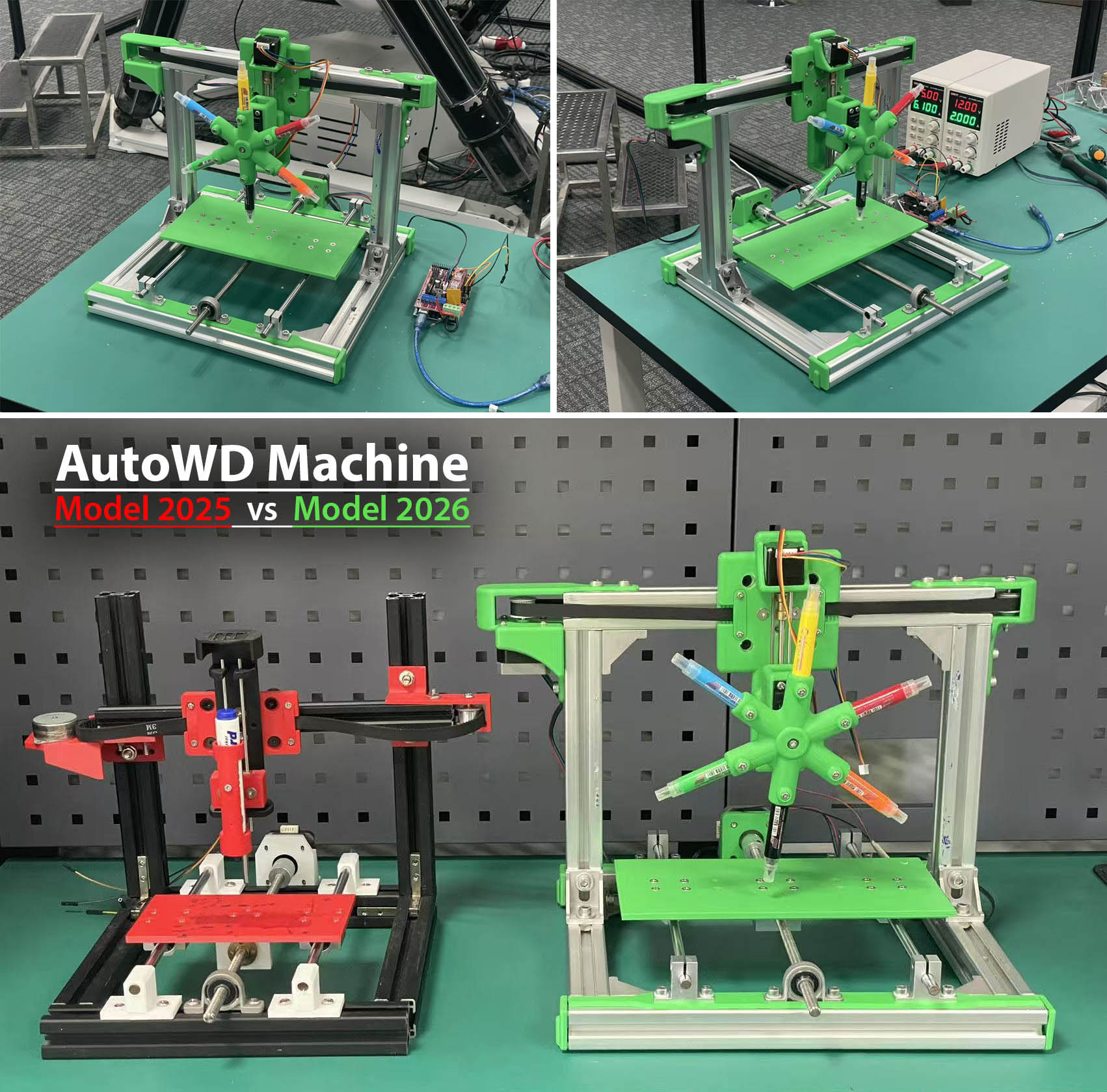
This year, our FAB Academy 2026 Team decided to focus on improving and developing further the concept of the Automatic Writing/Drawing Machine proposed by the FAB Academy 2025 Team at UNNC Fab Lab previously. We decided to name our machine "AutoWD-2026", refering to "Automatic Writing & Drawing" machine "model 2026".
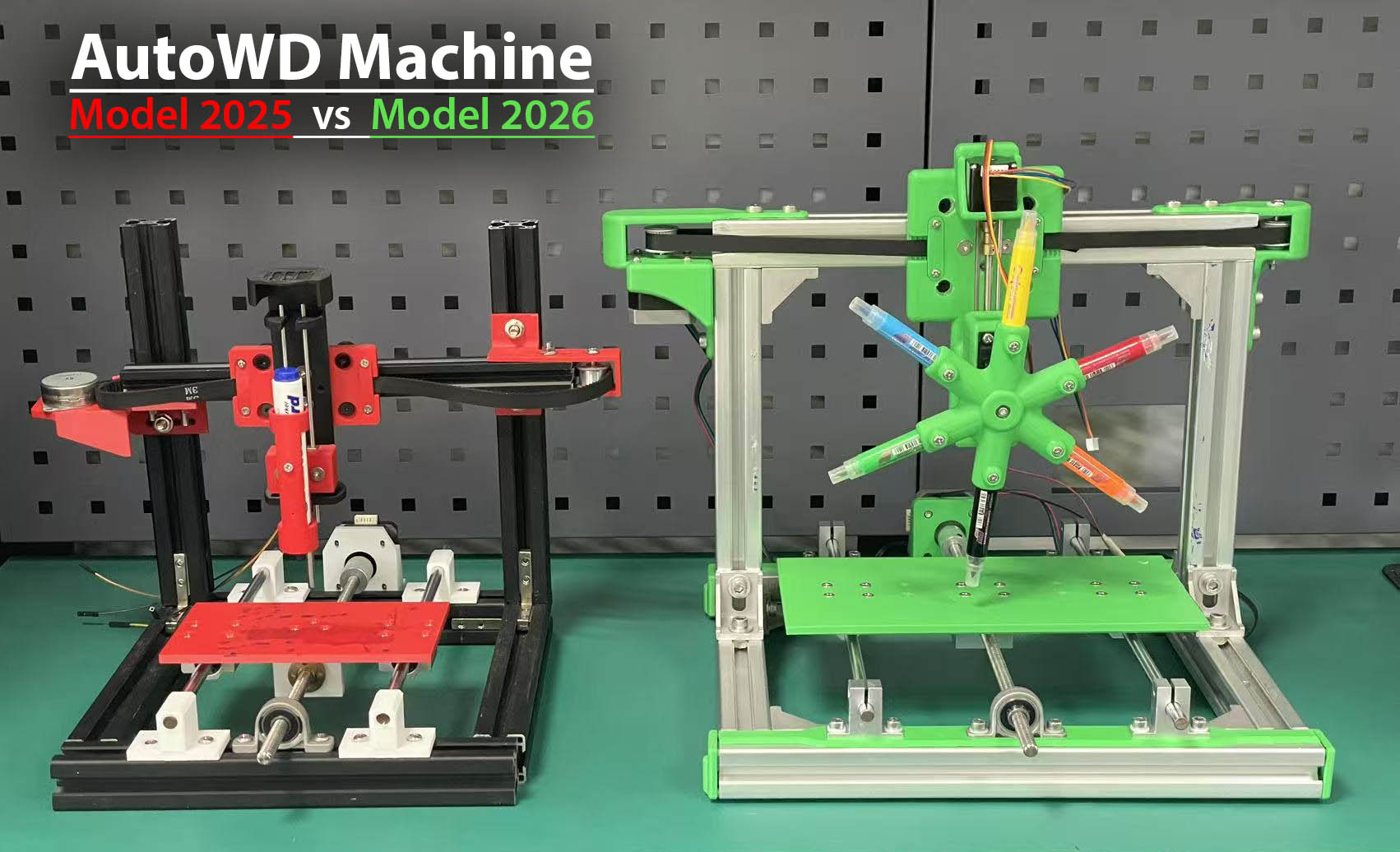
- Mechanical Specifications
| Description | AutoWD-2025 | AutoWD-2026 |
|---|---|---|
| # of Axis | 3 Axis | 4 Axis |
| Pen Holder | 1-pen | 6-pen (rotating) |
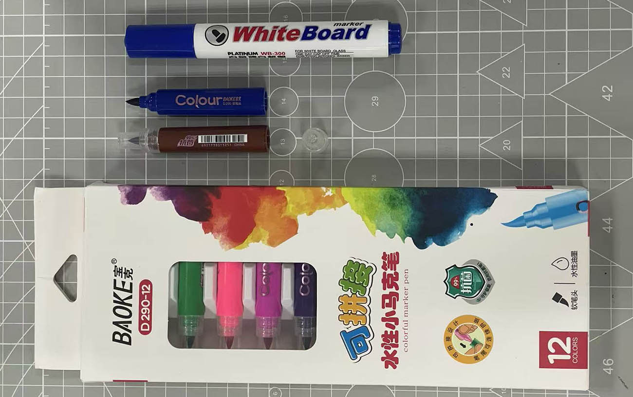
| Pen(s) | WhiteBoard Marker | BAOKE D290-12 Colour Markers |
| Bed Size (mm) | 155x90 | 250x125 |
| External Size (mm) | 365x360x280 | 435x415x340 |
| Frame Size (mm) | 255x280x285 | 330x330x295 |
| Aluminum Frame Profile | 30x30 + 20x20 | 30x30 |
| 3D printed Components | PLA (Red & Black) | PLA (Green) |
| X Axis | 42 Step Motor | 42 Step Motor |
| Y Axis | 42 Step Motor | 42 Step Motor |
| Z Axis | Step Motor J75A64BT | 28 Step Motor |
| B Axis | n/a | Servo Motor MG996R (360°) |
| Y & Z Movement | Smooth Rods + Lead Screws | Smooth Rods + Lead Screws |
| X Movement | 10mm Belt + Timing Pulleys | 10mm Belt + Timing Pulleys |
| Y Movement | T8 Lead Screws + Smooth Rods | T8 Lead Screws + Smooth Rods |
| Z Movement | T8 Lead Screws + Smooth Rods | T5 Lead Screws + Smooth Rods |
| Linear Actuator Carriage Plate | for 20x20mm Profile | for 30x30mm Profile |
- Electrical Specifications
| Description | AutoWD-2025 | AutoWD-2026 |
|---|---|---|
| Motion Control | RAMPS 1.4 Shield + x3 A4988 Motor Driver | RAMPS 1.4 Shield + x4 A4988 Motor Driver |
| MCU | Arduino Mega 2560 | Arduino Mega 2560 |
| Power Supply | One External | Two External |
| Others | n/a | Dupont Jumper Wires |
- The pens/markers we selected (our new "short" ones below the "big" one from 2025 at the top of the picture)
STEP 1: Kick-Off Meeting
On the first day of our project, we organised a kick-off meeting to discuss what will be our "Mechanical Design & Machine Design" challenge this year. We all agreed on improving and developing further the concept of the Automatic Writing/Drawing Machine proposed by the UNNC FAB Academy 2025 Team.
Key improvements and devolpments proposed:"
- Improve Z Axis (based on the past year experience)
- Increase Bed Size (and therefore the machine size as well)
- Add a Rotating Multi-Pen Holder (up to 4/6/8 pens)
- Improve Ease of Assembling the Machine (mechanism alignments)
- (Not implemented) Add an Automatic Paper-Roll Feeder (for continuous writting/drawing - e.g. Banner, etc)
Team Members's Key Responsabilities:
- Software & Electrical Control Engineer: Le LI
- Structural & Mechanical Engineer: Loïc FAULON
- Project Supervisors: Bob WU & Yaorun ZHANG
- Design & Debugging Experts: All of us 😃 😃 😃
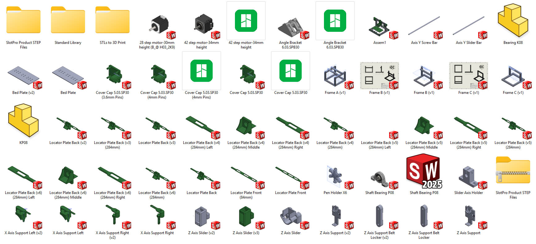
STEP 2: CAD with SolidWorks (Loïc)
The CAD modelling process followed a well-planned, methodic, and progressive approach with a number of iterations depending on the components. The image below illustrates the numerous CAD files and folders created to support a clean organisation of the data and smooth process.
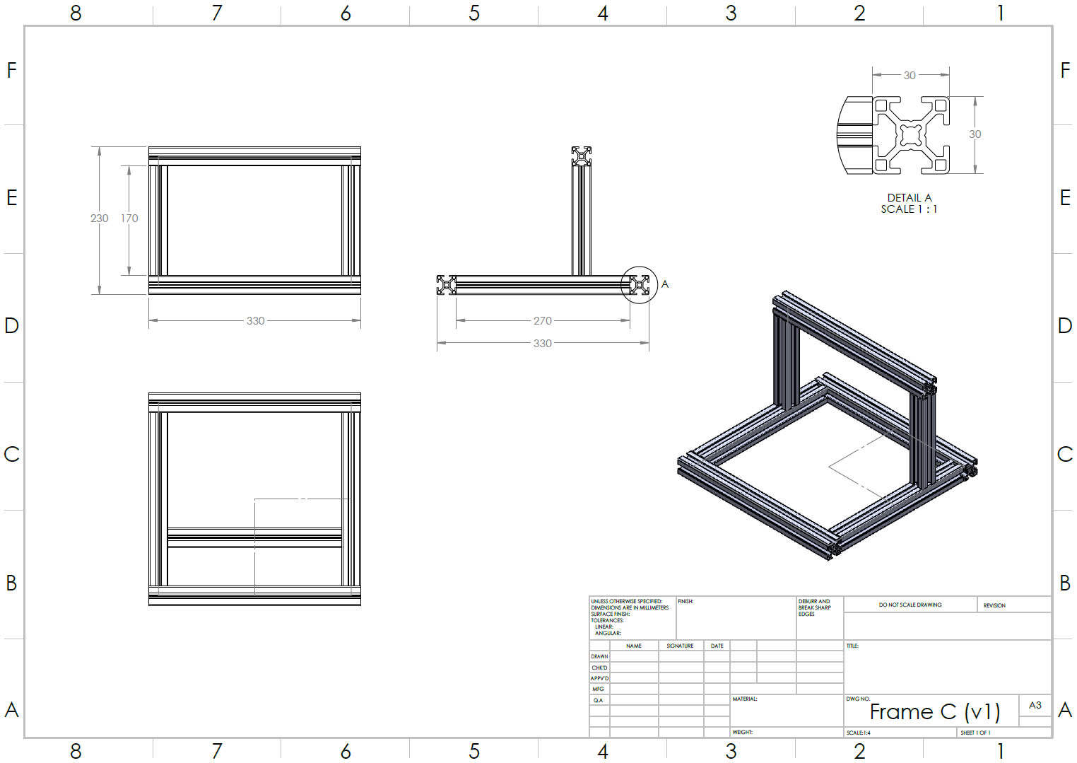
1. Modelling of the Frame
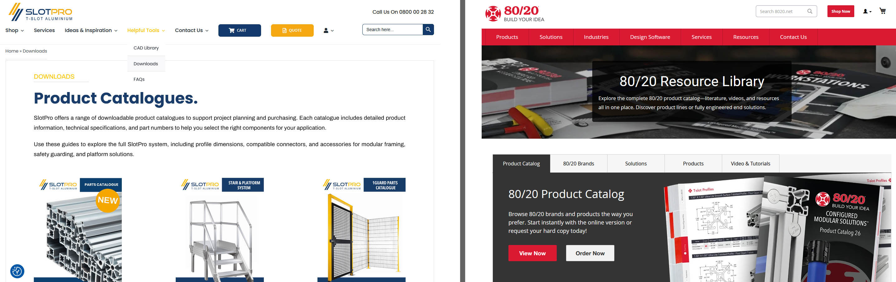
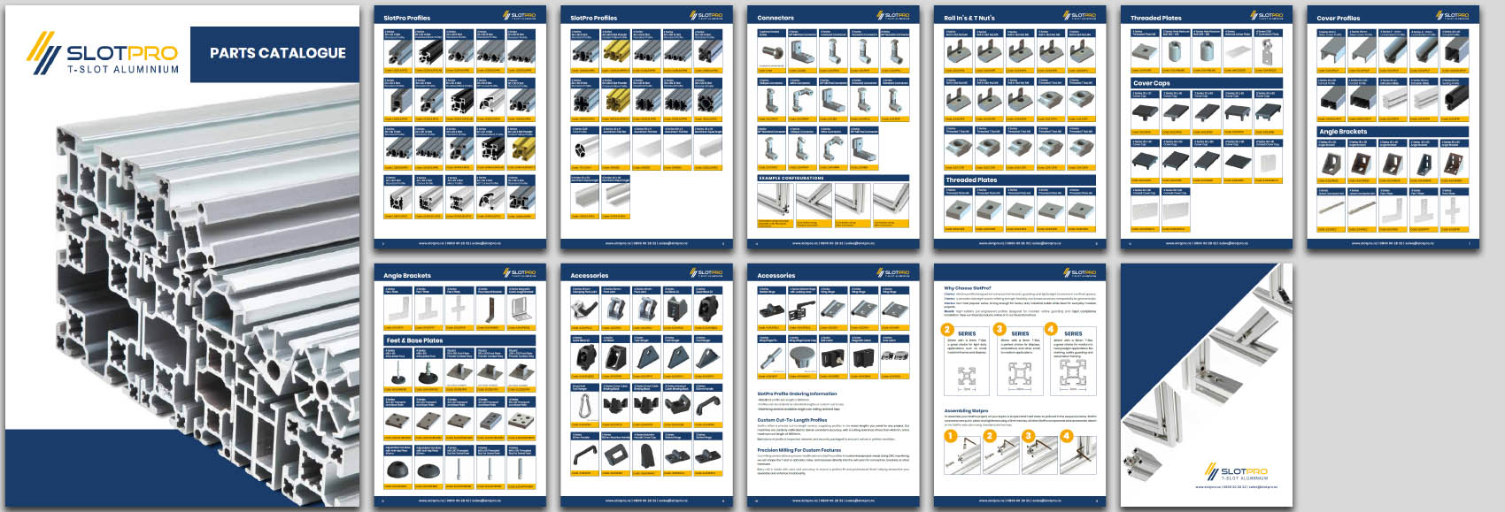
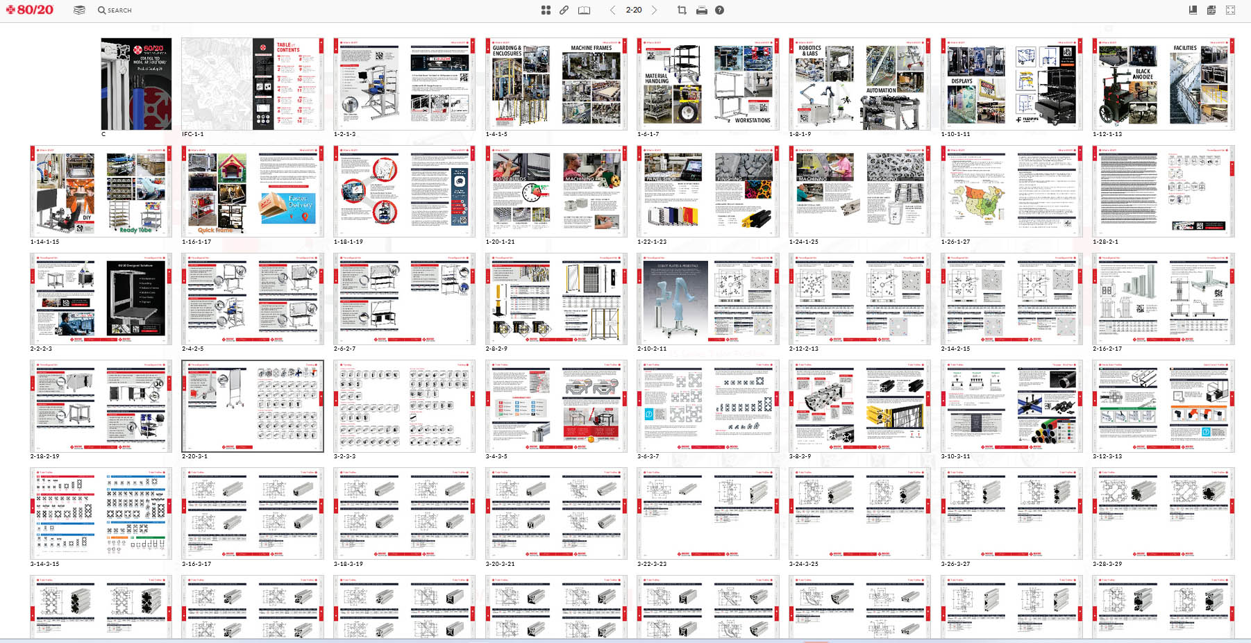
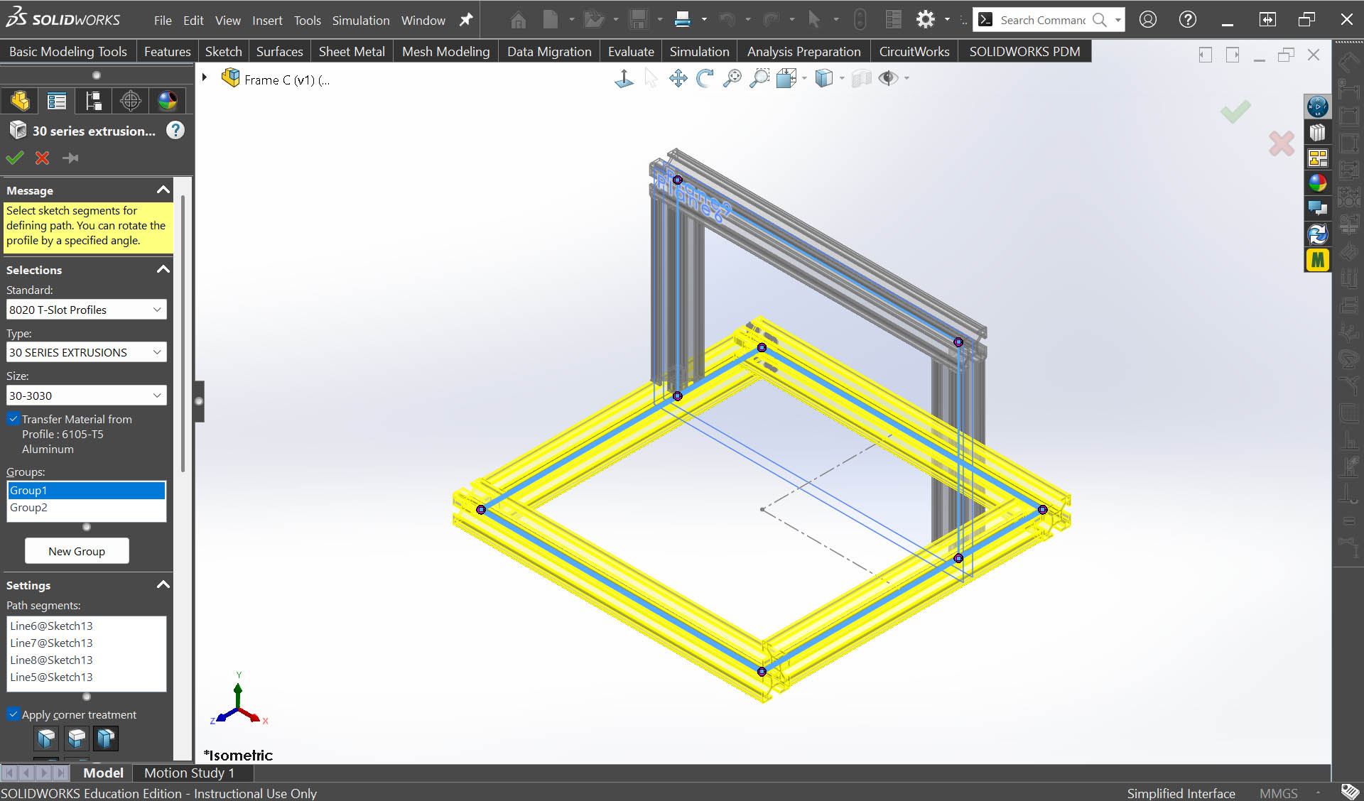
I have applied the "Weldments" with "Structural "Members" technique available in SolidWorks to model the whole structure of the frame from two very simple 2D sketches. Instead of modelling myself the T-Slot profile, I decided to look online for a database. Luckily, I found two manufacturers/suppliers, SLOTPRO and 80/20, with excellent catalogues to refer to and complete CAD Libraries... and the possibility to download them easily and install them in my SolidWorks' library. 😃 😃 😃
- SLOTPRO and 80/20 website landing pages and Catalogues
- Frame design in SolidWorks
2. Design of the Plastic Components in SolidWorks
The design of the plastic components in SolidWorks (all 3D printed along the development process) has been the most time-consuming activity. Sometimes, several iterations were needed due to functional, dimensional, and/or ease of assembly/disassembly refinements.
The Design & Development strategy applied has been to work from "Bottom-to-Top" of the machine, or from "Base-to-End" (Penholder), insuring all parts fitted well on the frame and between themselves, with good function, before starting the design of the next part/component.
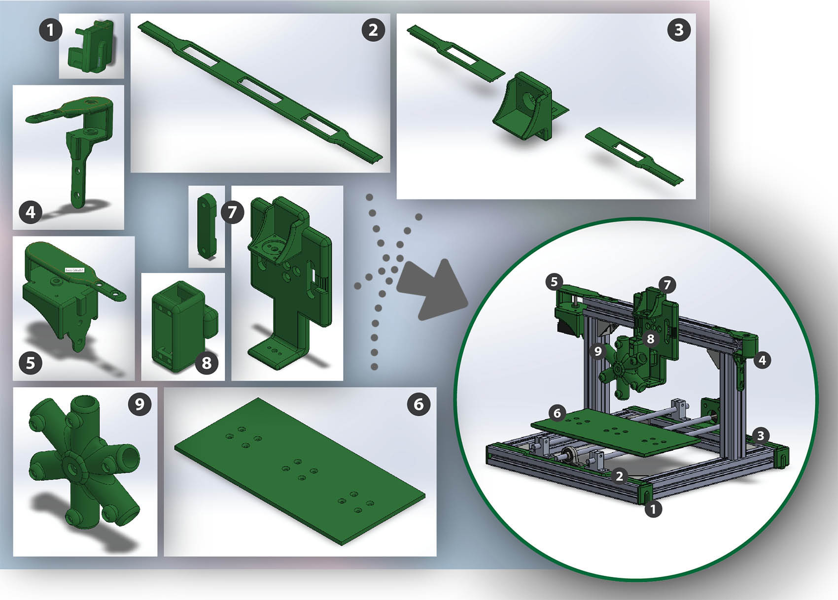
Here is the design-flow of the parts/components:
    1. Frame Base Cover Caps
    2. Y Axis Locator Plate Front
    3. Y Axis Locator Plate Back (with step-motor)
    4. X Axis Support Right
    5. X Axis Support Left (with step-motor)
    6. Bed Plate
    7. Z Axis Support + Z Axis Support Belt Locker
    8. Z Axis Slider
    9. Rotational 6-Penholder
STEP 3: Manufacturing & Assembly (Loïc)
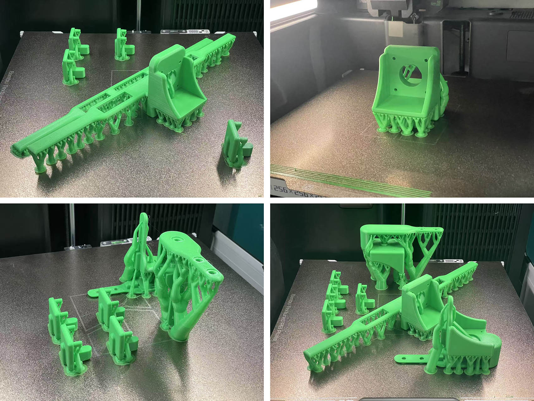
1. Production of the 3D Printed Components
- For the manufacturing, we mainly used 3D Printing to produce our custom design components. All the them are made of a bright green PLA... hours and hours of days and nights production!
- Generated Waste: (to be aware of...)
Because of supports needed for some parts and because of some iterations for design refinement and "fine-tuning", we did unfortunatly produce some waste as well. 😦 😦 😦
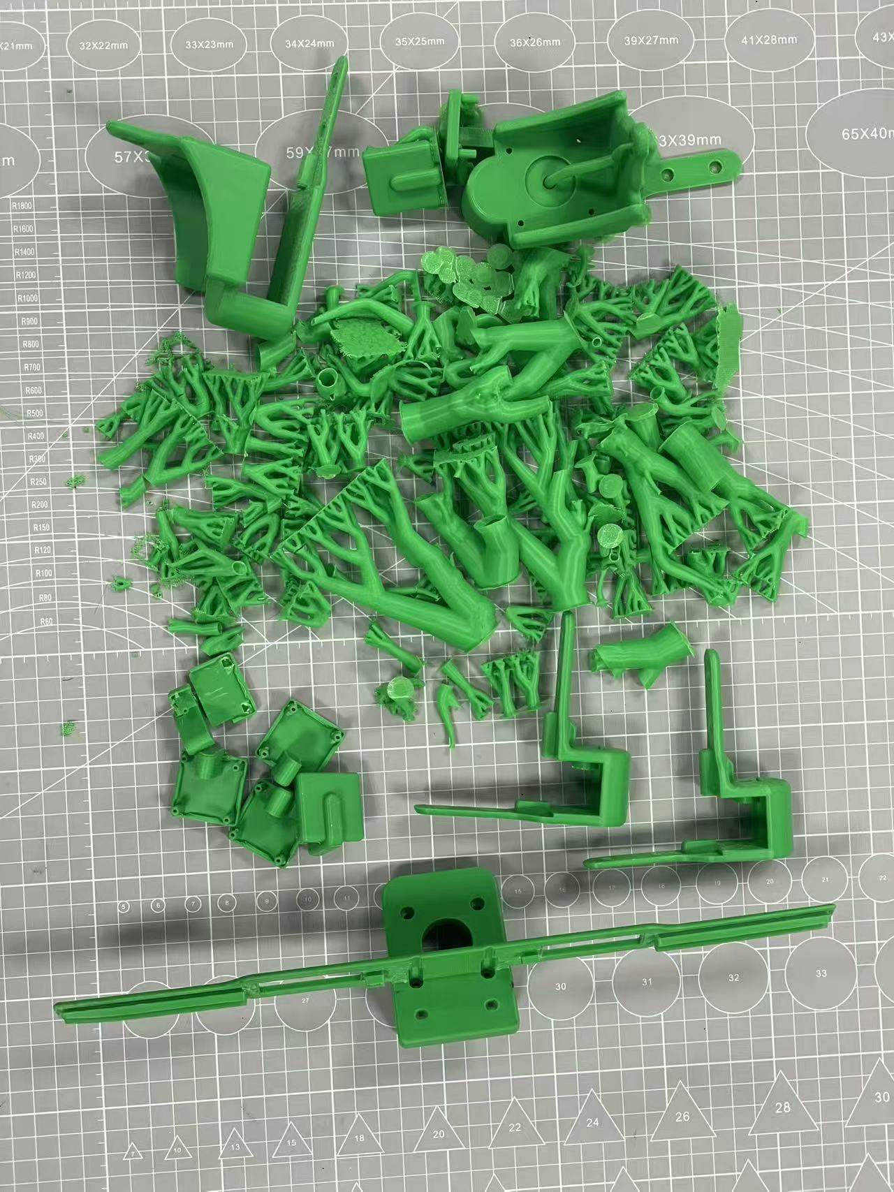
We should try to minimise this as much as possible!!! 😉
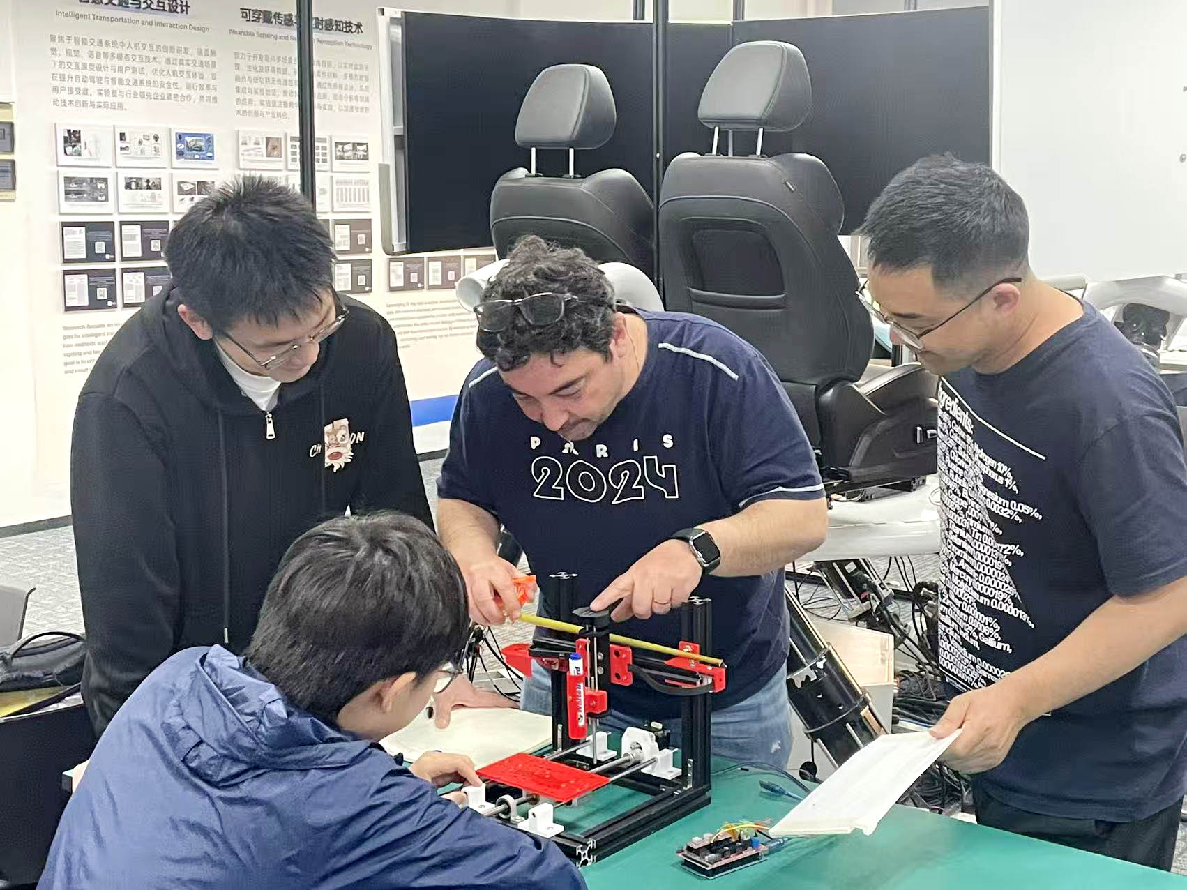
2. Structural and Mechanical Assembly
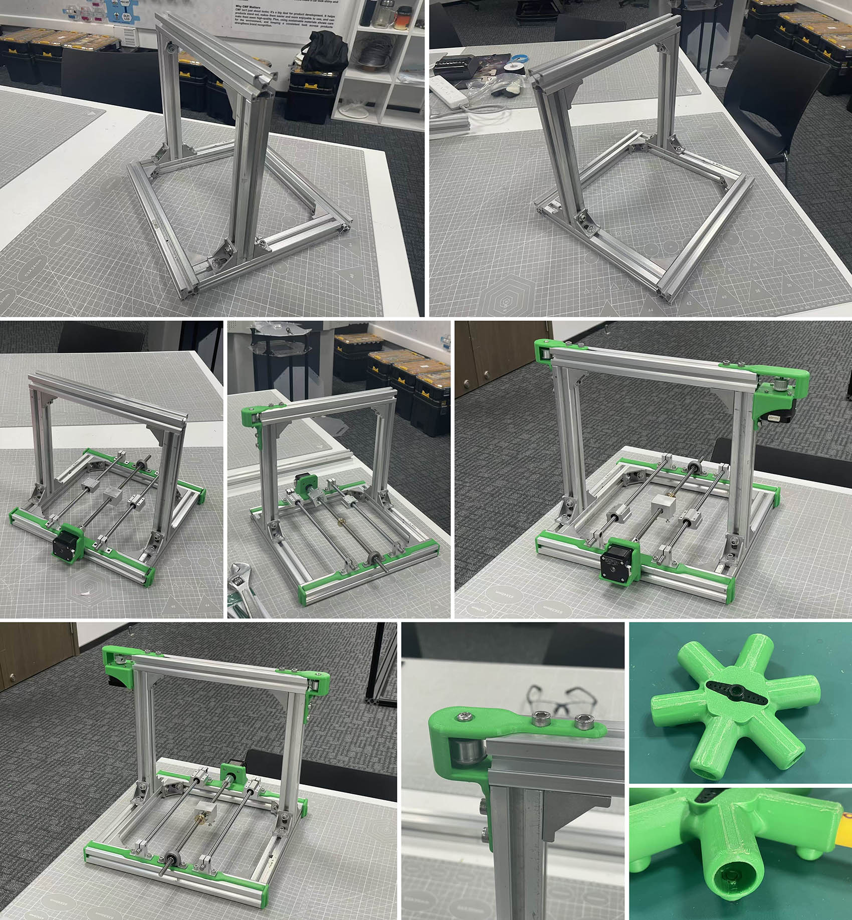
"In ACTION"... with a bit of help from our local Instructors 😃 ...to make it on time! (@ Bob & Yaorun... Thank you very much, WE LOVE YOU)
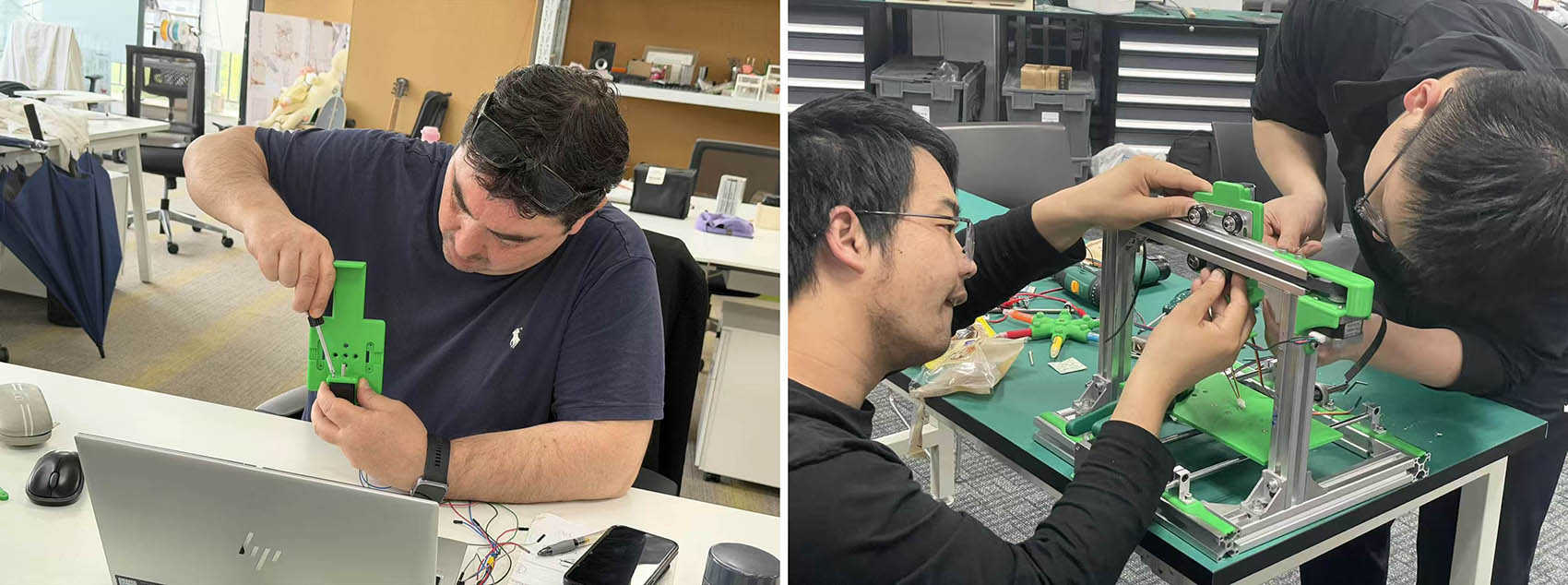
STEP 4: Electronic Control (Le)
Please refer to my colleague Le's web page for more details and illustrations 😉
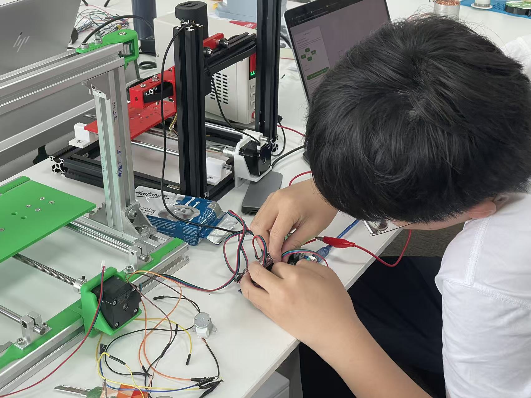
STEP 5: Testing & Debug (All of us)
Please refer to my colleague Le's web page and our UNNC Fab Lab web page for more details and illustrations 😉
Final TEAMWORK Outcome
Video Credits to Le 😉