Appearance
WEEK 10 – Output Devices
Assignments
Group Assignment
- Measure the power consumption of an output device
Individual Assignment
- Add an output device to a microcontroller board you've designed, and program it to do something
Group Work
Our group work is accessible HERE (add the link)
Individual Work
PART ONE 😃
This first Output Device test is the continuity of my Input Device test (week 9) which should trigger a Relay as Output (reference: JOC-3FF-S-Z) when two Input conditions are fulfilled: Object within 25cm + Red colour detected = Relay ACTIVATED.
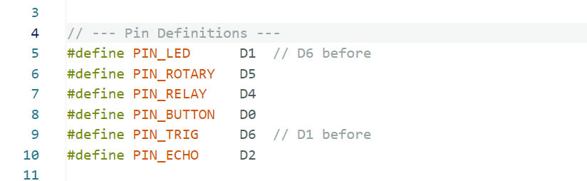
Pin Assignment Plan:
| Pins (IAO-ESP32-S3) | Signal Name |
|---|---|
| D0 | 6*6 Puch Button Switch |
| A6 | Ultrasonic Sensor TRIG |
| A2 | Ultrasonic Sensor ECHO + Resitor 1000 Ω |
| D4 | Relay IN |
| A5 | Rotational Sensor OUT |
| D1 | LED + |
| GND | Ultrasonic Sensor / Rotational Sensor / Relay / LED - / Ultrasonic Sensor ECHO + Resitor 2000 Ω |
| VCC | Ultrasonic Sensor / Rotational Sensor / Relay / 6*6 Push Button Switch |
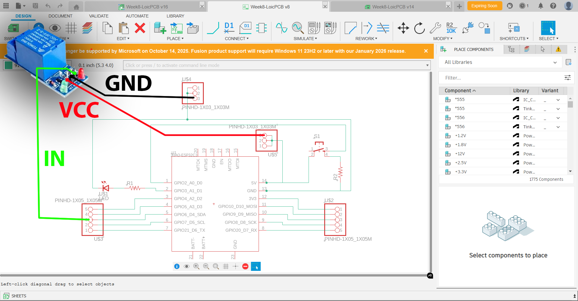
Schematic/Wiring:
Codes for the Relay in Arduino IDE:
(Refer to Week 9 for the complete codes)
  // 4. Dual Condition Relay Logic (AND)
  Serial.printf("| Dist:%.1fcm | Red:%s | ", distance, isRed ? "YES" : "NO");

  if (isNear && isRed) {
    digitalWrite(PIN_RELAY, HIGH);
    Serial.println(">>> RELAY: ACTIVE <<<");
  } else {
    digitalWrite(PIN_RELAY, LOW);
    // Debug specific missing condition
    if (isNear && !isRed) Serial.println("[WAITING FOR RED]");
    else if (!isNear && isRed) Serial.println("[OBJECT TOO FAR]");
    else Serial.println("[IDLE]");
  }
Circuit Implementation & Test:
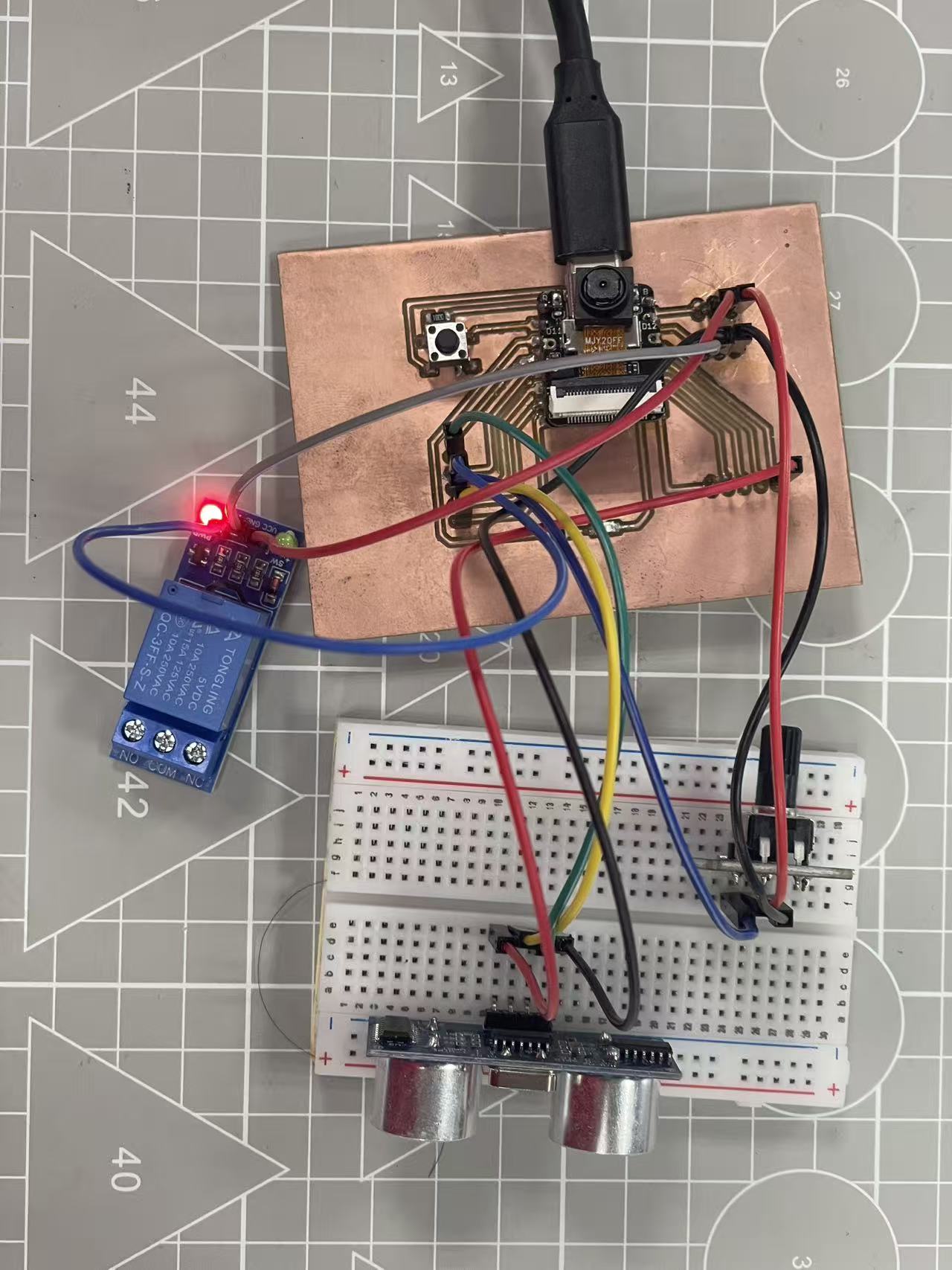
SUCCESSSSSSS!!! 😃 😃 😃
PART TWO 😃
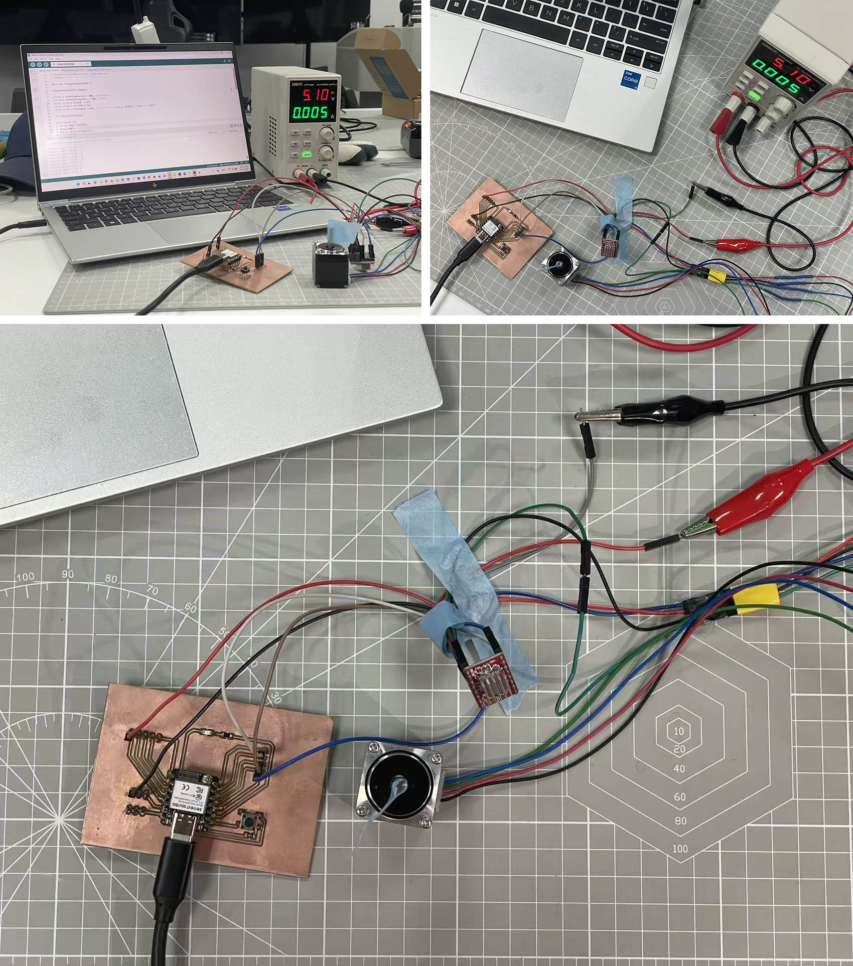
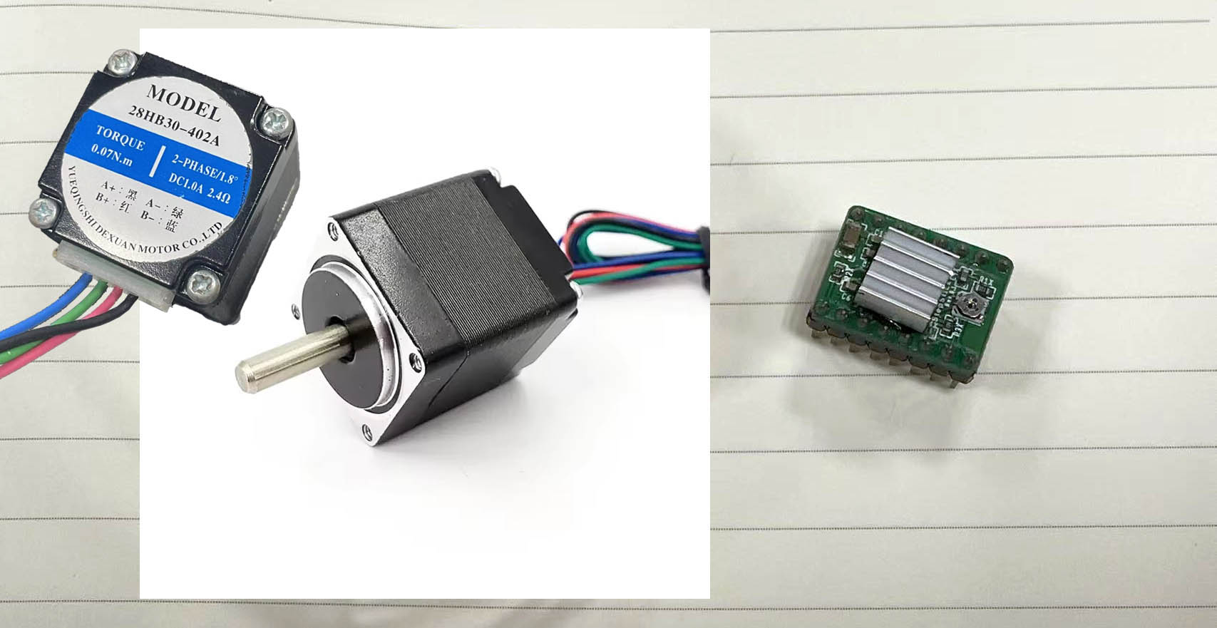
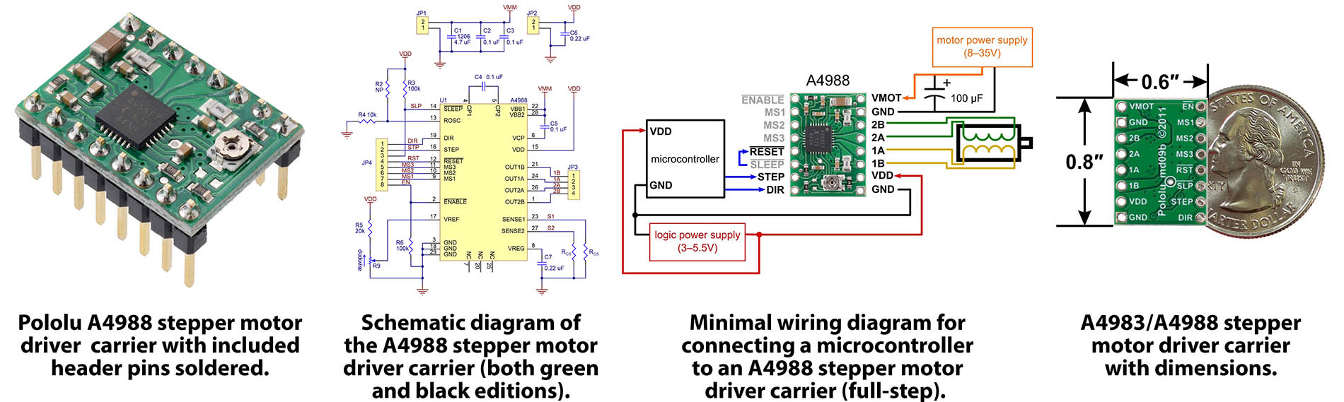
For my second Output Device test, I decided to use a Step Motor (model 28HB30-402A) and a Stepper Motor Drive Module with Heat Sink (model A4988). This is a useful test as we might need it for our Machine Design in a few weeks time.
Pin Assignment Plan:
| Pins (IAO-ESP32-S3) | Signal Name |
|---|---|
| D0 | 6*6 Puch Button Switch |
| D1 | LED + |
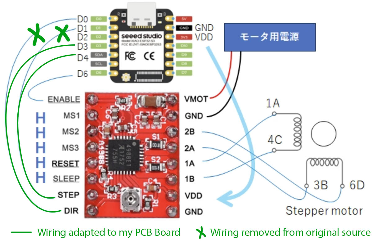
| D3 | A4988 S.M.D. DIR |
| D4 | A4988 S.M.D. STEP |
| D6 | A4988 S.M.D. ENABLE |
| VCC 3V3 | A4988 S.M.D. VDD |
| GND | A4988 S.M.D. GND / LED - |
| VCC 5V | 6*6 Push Button Switch |
Circuit Connections:
 (
(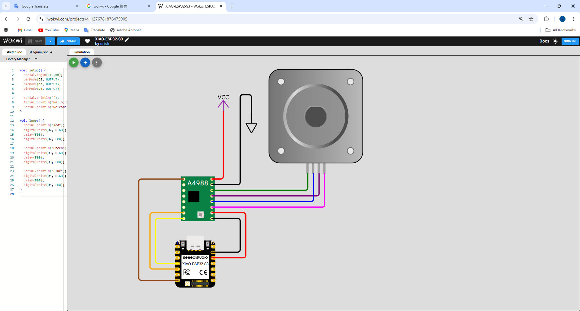
Codes in Arduino IDE:
(Original Code Source)
//steppermotorA4988withclass_singleDEMO.ino
// A4988ステッピングモータードライバーモジュール

#include "StepperMotorESP32.h"

StepperMotorESP32 stepper;

uint32_t MinPulsePeriod = 200; //[microsec]
uint32_t ControlFrequency = 100; //[Hz]
const uint8_t PinDIR  = D3;
const uint8_t PinSTEP = D4;
const uint8_t PinEnable = D6; // モータドライブEnable(府論理)に使用する PIN番号

int MaxControlValue;

void setup() {
  Serial.begin(115200);
  delay(100);
  Serial.println("Hello");

  stepper.setPins(PinDIR, PinSTEP, PinEnable);
  stepper.setDirModifier(1);
  MaxControlValue = stepper.getMaxControlValue(ControlFrequency, MinPulsePeriod);
  Serial.print("MaxControlValue = ");
  Serial.println(MaxControlValue);
  stepper.enableDriver();
}

void loop() {
  static int control = 0;
  static int dcontrol = 1;
  static int n=0;
  int res;
  double fcontrol = (double)control/50.;
  res = stepper.drive(fcontrol);

  n++;
  if (n == 100) {
    if (control == 5 || control == -5) {
      dcontrol *= -1;
    }
    control += dcontrol;
    n=0;
    Serial.print("control, res = ");
    Serial.print(fcontrol);
    Serial.print(", ");
    Serial.println(res);
  }
  delay(1000/ControlFrequency); //[msec]
}
Circuit Implementation & Test: