This week my team and I built a 3-axis CNC engraver for drypoint printmaking. My specific contribution was in the enclosure design and manufacturing: from the structural aluminum tubing (cutting, drilling, painting) to the infinite-screw shafts and rod preparation, the laser-cut and table-saw machine bed, and the full fabrication and assembly of the plywood enclosure box.
The goal for this week was to design and build a machine with mechanism, actuation,
automation, function, and a user interface.
My individual workflow focused on the enclosure and mechanical support parts:
Understand the group machine concept and define what parts I would contribute.
Prepare the structural material, including aluminum tubing, rods, shafts, and plywood panels.
Fabricate the enclosure parts using CNC, laser cutting, table saw work, drilling, sanding, and assembly.
Document how my enclosure work connected to the full group machine.
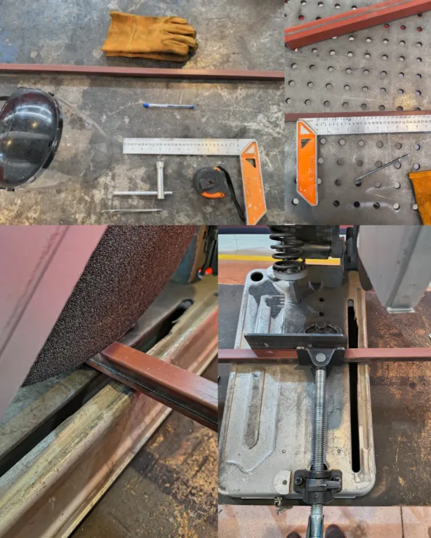
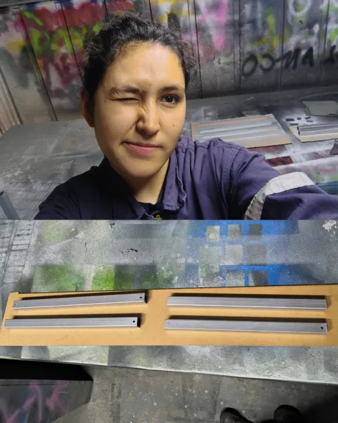
The main structural frame uses square aluminum profiles that needed to be cut to precise lengths, deburred, drilled for fasteners, primed, and painted. Below is the full process from raw stock to finished painted pieces.
1. Tools & Measurement Setup
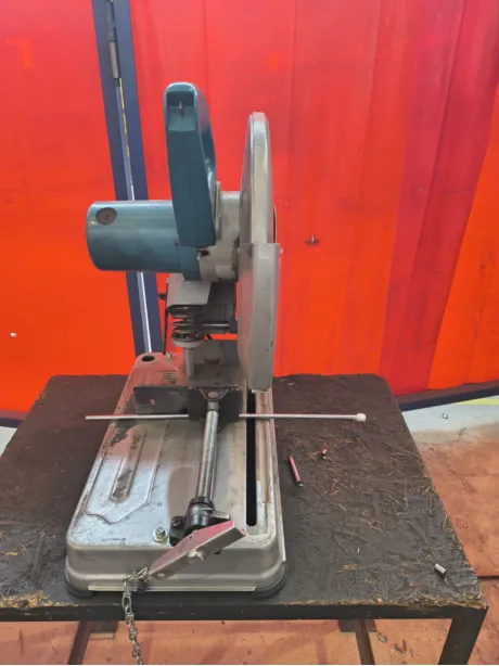
Each profile was measured and marked at 30 cm with a carpenter's square, and a metal scratcher. Once it was marked, the piece was fixed on the miter saw at 90 degrees, and lowered the disk without turning the machine on to ensure a clean cut.
2. Cutting the Profiles
The tube was secured against the fence and cut in a controlled pass to avoid deflection and keep a clean edge.
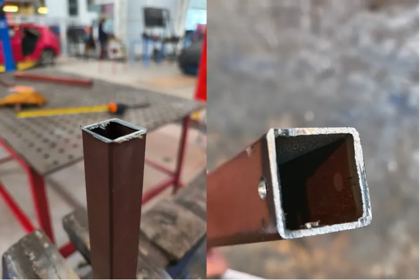
3. Deburring the Cut Edges
A file was used to remove burrs and smooth the cut face flush after every cut.
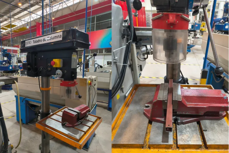
4. Drilling the Fastener Holes
The drill press helped making precise, perpendicular holes for the M4 fasteners that join the profiles to the 3D-printed corner joints.
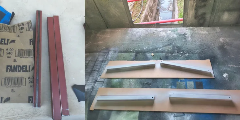
5. Sanding & Priming
All profiles were lightly sanded with a 240 grit sandpaper to remove surface oxidation and improve paint adhesion. Then 3 coats of primer were applied.
5. Final Paint Finish
A metallic spray paint was applied over the primer for a clean, finish.
Process 02
Lead Screws & Guide Rods
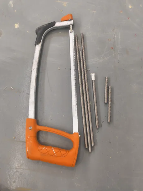
The motion transmission system relies on lead screws (infinite screws) and smooth steel guide rods. The smooth steels guides were cut with the miter saw, while the lead screws were cut manually with a hacksaw. In both cases, the ends were beveled on a bench grinder for clean insertion into mounted bearings and couplers.
1. Positioning the Guide Rod in Mitter SAW
The smooth steel must be really tight as it can slip when cutting.
2. Cutting the Lead Screws with a Hacksaw
A hacksaw and a bench vise were used to hold the pieces while cutting the threaded rod without stripping the thread pitch.
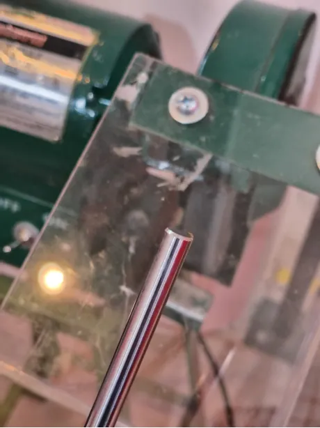
3. Beveling Ends on the Bench Grinder
After cutting, each shaft end was touched to the bench grinder wheel to create a clean bevel. Preventing damage to the components and ensuring proper assembly.
Measures
Quantity
Lead screw
Guide rod
2
324 mm
306 mm
1
277 mm
260 mm
1
77 mm
—
2
—
87 mm
Process 03
Machine Bed
The machine bed provides the flat work surface where plates are held during engraving. Fabricated from MDF and plywood. The total thickness was of 24mm, and consisted of two 3mm mdf layers and a 18 mm triplay.
1. Laser Cutting
This was used to cut the precise holes for the bed panels. It's general measurements were 346mm x 346mm. The parameters used for cutting were: Power at 70-60% and 25 mm/s. While the engraving parameters were 30-20% at 200 mm/s.
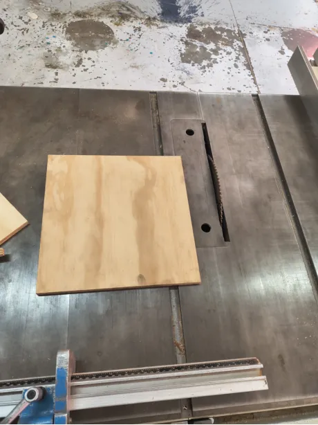
2. Table Saw Cuts
The layer of triplay was cut to size using the table saw. The general measurements were 310 mm x 310 mm. After the pieces were cut, they were sanded and assembled together.
Process 04
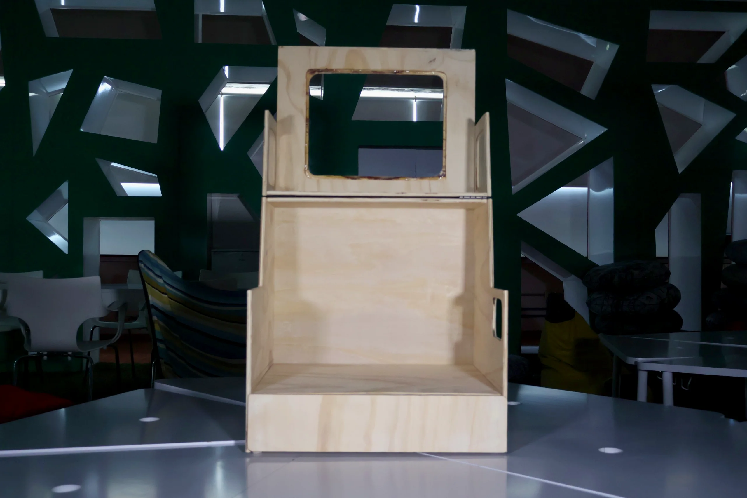
Enclosure Design & Fabrication
The enclosure protects the CNC machine, stores tools in a dedicated drawer, and provides clear visibility during operation.
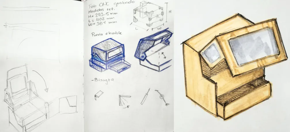
1.Sketches & Concept
These first step to design the enclosure involved hand-drawn sketches that explore the overall shape, proportions, and layout. Thinking about the functional requirements and user experience was key in shaping the initial concepts. And led to the final concept which was: A enclosure with a lift-up front door for easy CNC access, a bottom drawer for tool storage, and acrylic windows on the sides and top for visibility during operation.
2.3D Model in Fusion 360
After the concept was finalized, I created a hybrid design in Fusion 360, allowing me to model composite parts and assemble them simultaneously. Which helps to achieve precise joinery and accurate cut layouts.
3. DXF Export VCarve Configuration
I exported the DXF and made workarea rectangles acording to the material I had. Then I loaded them into VCarve to configure toolpaths, depths, and profiling passes following week 7 workflow. The tool parameter were: 0.25 inch end mill, with a pass depth of 0.1 in, and a stepover of 40%. The spindle speed was set to 18000 r.p.m, a feed rate of 450 inch/min, and a plunge rate of 23.62 inch/min.
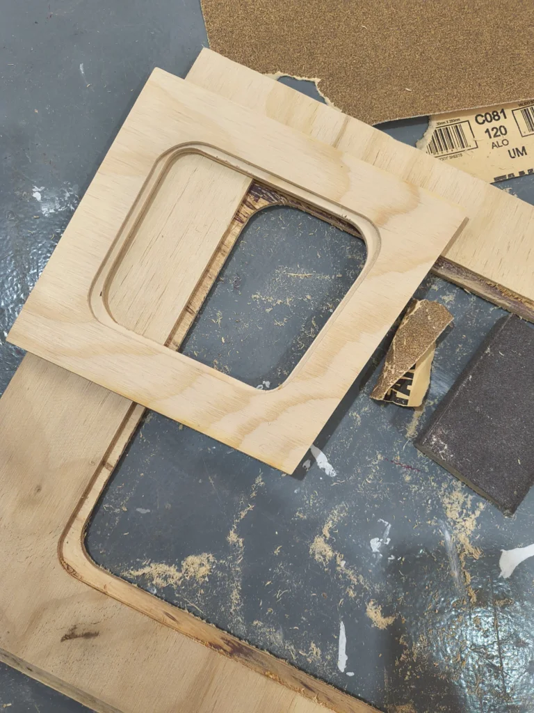
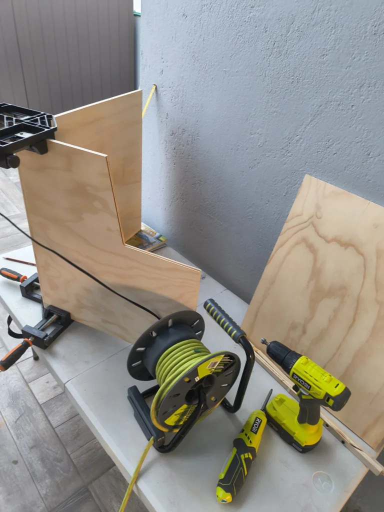
4. CNC Router Cutting
Most of the pieces were CNC cutted, especially because the windows had pockets for the acrilycs. The pieces that were not CNC cut were hand-cut with a panel saw
5. Panel Saw Cutting
The simplier geometries like rectangles and straight lines were cut using a panel saw.
6. Belt Sander
After cutting, all edges were sanded smooth with a belt sander, just in the necessary areas, because if you sand too much, you can damage the material or affect the fit.
6.2 Surface Prep
Some panels were addinionally sanded with 120-grit paper to remove machine marks and clean joint skins. For example, the edges of the acrylic windows were sanded to ensure a smooth finish before bonding.
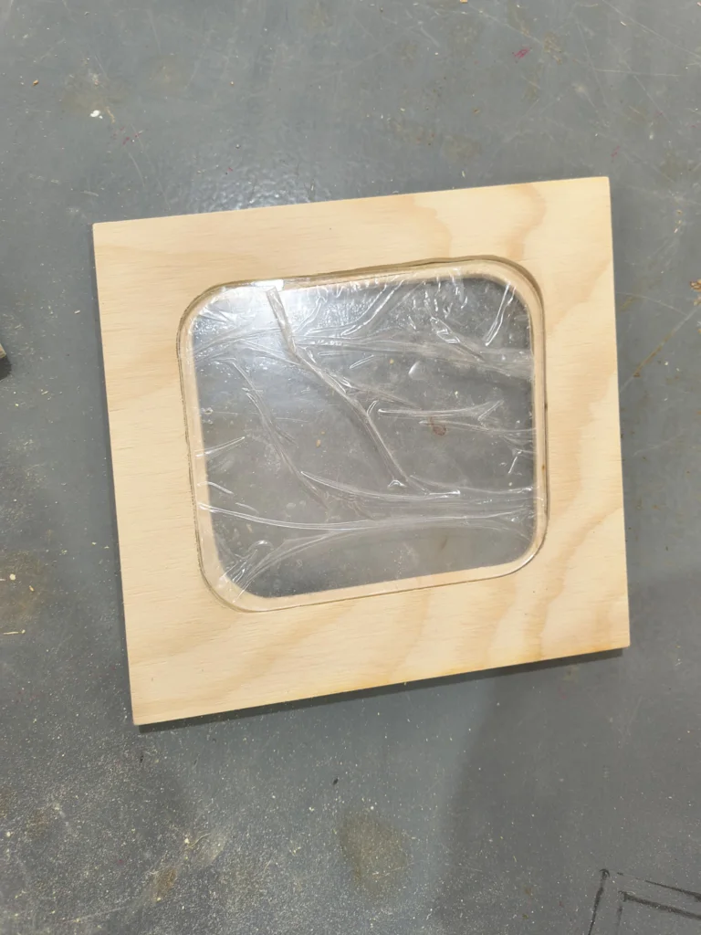
7. Acrylic Windows
The laser parameters for 3mm acrylic were 70-60% at 25 mm/s. The cuted pieces were sanded afterwards because the fit was too tight.
8. Gluing Acrylic Panels
After the acrylic panels were trimmed and test-fit they were glued with clear epoxic adhesive. I used the JB WELD, clear weld one, it takes about 5 minutes to set.
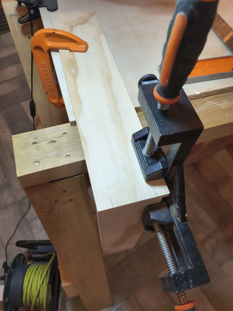
9. Base Assembly
The base box was assembled using corner clamps to hold panels square and then fastened with #6 wood screws.
10. Tool Storage Drawer Box
The tool storage drawer box was assembled separately, with the front, back, sides, and bottom glued and clamped together.
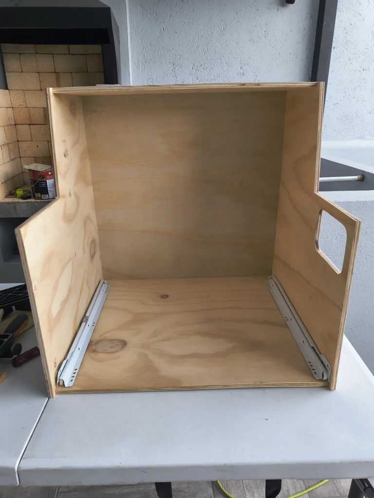
11. Drawer Slides Installation
After the base part composites were complited, drawer slides (rails) were installed on the inside of the base cabinet and on the drawer box, ensuring smooth and aligned operation.
11.2 Drawer Slides Installation
40 cm bottom-mount roller slides were used, installed along the bottom center of each drawer with a self-closing mechanism.
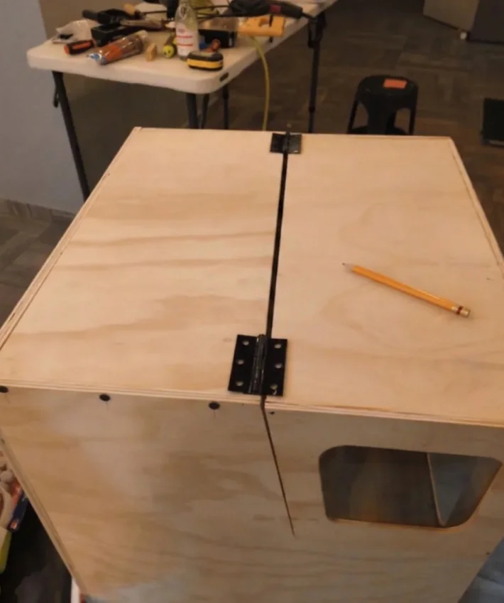
12. Hinge Installation
Then hinges were installed along the idth of the lift-up front door, providing even support and smooth operation across the door's span.
13. Internal Mounting Platform
Lastly, an internal mounting platform was built and installed inside the enclosure to seat the CNC machine at the correct height.
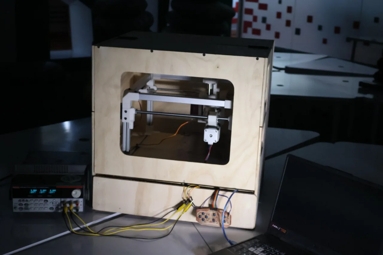
Here is the final result of the enclosure assembly with the CNC machine installed
Learning Outcomes
9 mm Plywood Is Tricky Thin:
Thin 9 mm plywood warps easily, especially after routing. Several panels bowed slightly, causing gaps during assembly. Clamping strategy and glue selection matter a lot at this thickness.
Panel Separation During Assembly:
Some panels separated after initial glue-up, requiring re-clamping. The combination of thin stock and pocketed joints meant the glue surface area was sometimes too small.
Screw Length Mismatch on Hinges:
The default piano hinge screws punched through the 9 mm plywood. Each screw had to be swapped for shorter ones, and exit holes required filling and sanding.
Electronics Integration & Cable Management:
Cable lengths and routing paths should be designed in parallel with the enclosure, not after. Cables from the PCBs were too short to route neatly.
Discrete & Hidden Joinery:
In a future version I would use pocket-hole screws covered by plugs, or dado/rabbet joints, so no fastener heads or filler patches are visible on the surface.
Multi-Process Manufacturing:
Managing one project across four fabrication processes (laser, CNC routing, table saw, drill press) taught me that tolerances stack, 0.5 mm cut error on the laser can cause misalignment downstream.
Recognising Opportunities
For improvements in the design, I identified a few areas that could make the machine safer, cleaner, and easier to adapt in future iterations.
Soundproof Enclosure Materials:
A future version of the enclosure could use materials that help reduce noise, such as acoustic foam, rubber seals around the door, denser panel layers, or a laminated wall structure. This would make the machine more comfortable to use indoors while still keeping visibility and access.
Dedicated Electronics Housings:
The electronics should have their own protective cases instead of being mounted openly inside the machine. Designing separate housings for the controller, drivers, power supply, and wiring would improve safety, reduce dust exposure, and make maintenance easier.
Adaptable Work Table:
The work surface could be redesigned as an adjustable table that supports different material sizes. A modular bed with slots, clamps, or removable panels would make it easier to secure plates of different dimensions without redesigning the whole machine.