This week we explored about computer controlled machining (also know as CNC) which is a subtractive manufacturing process usually for large-scale fabrication. For this we traslated a digital design into toolpaths that a CNC machine can follow. The general workflow was:
Designing in a CAD software, in my case I did a drafting table on Onshape.
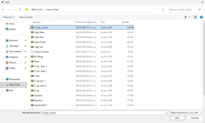
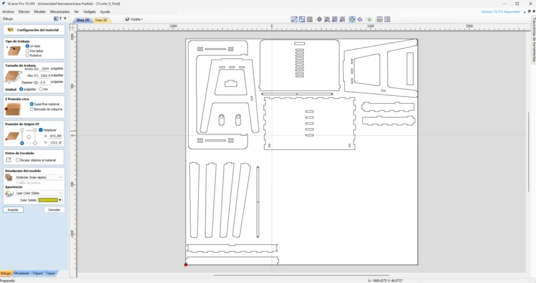
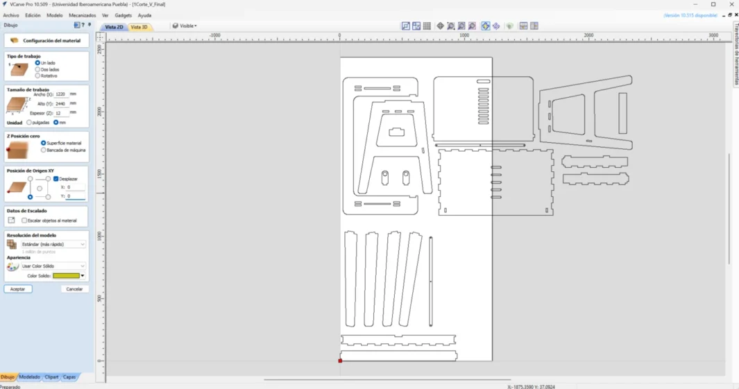
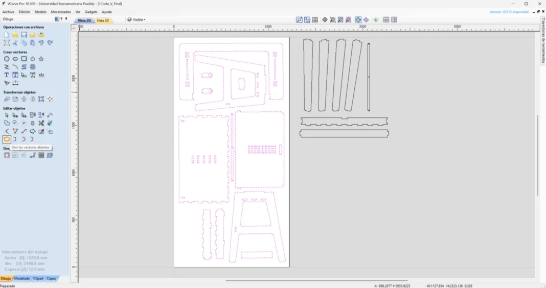
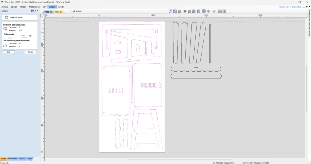
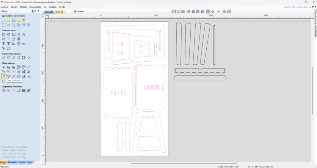
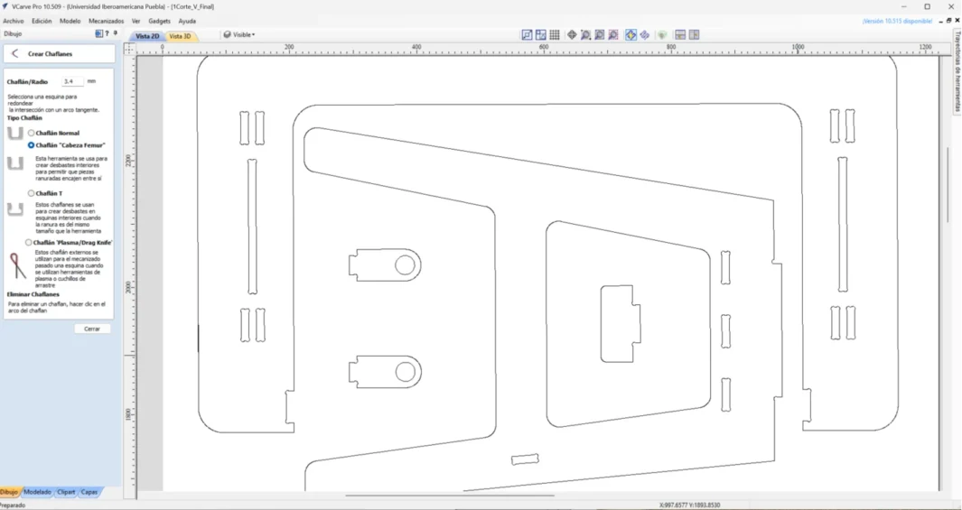
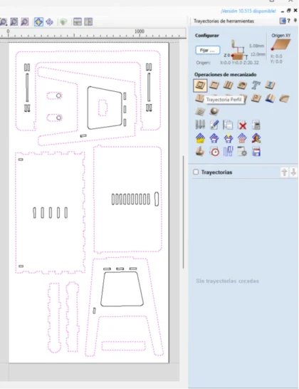
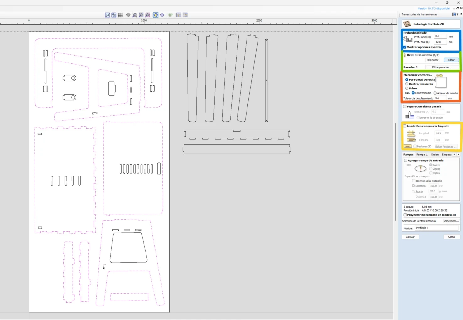
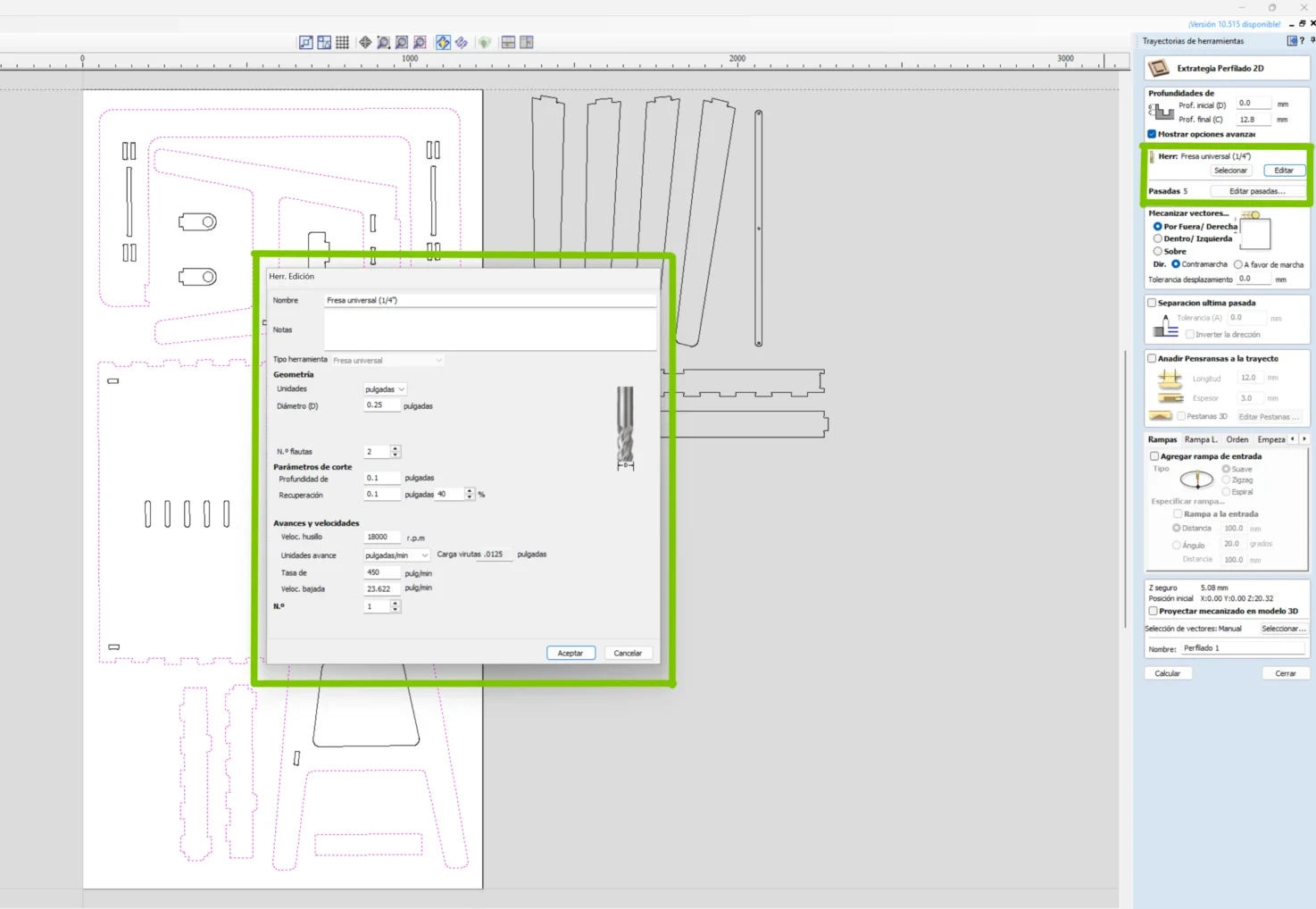
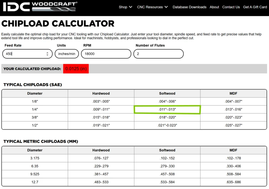
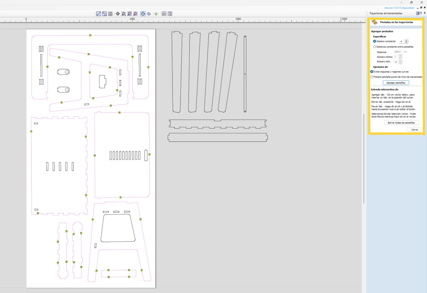
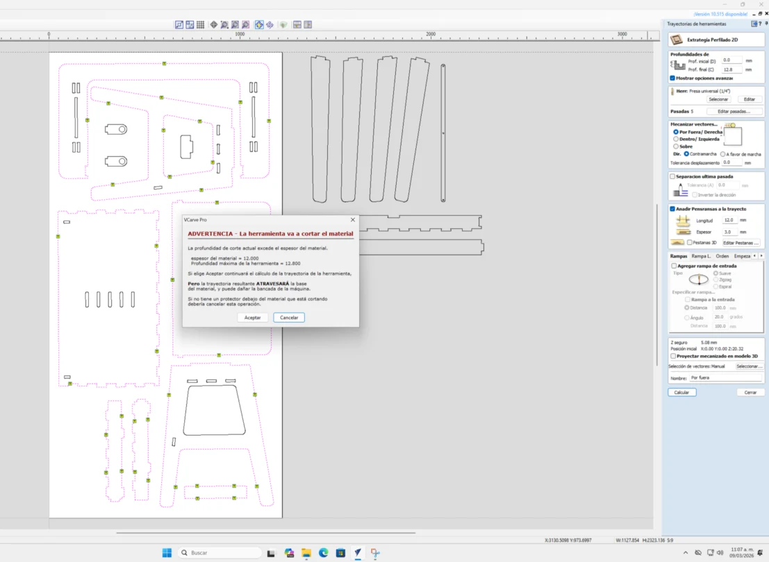
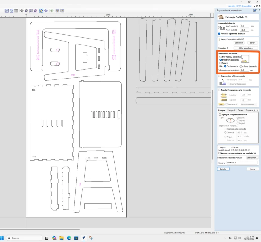
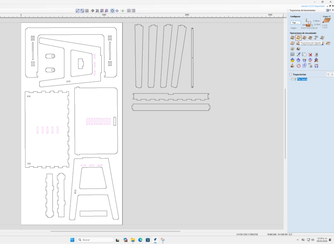
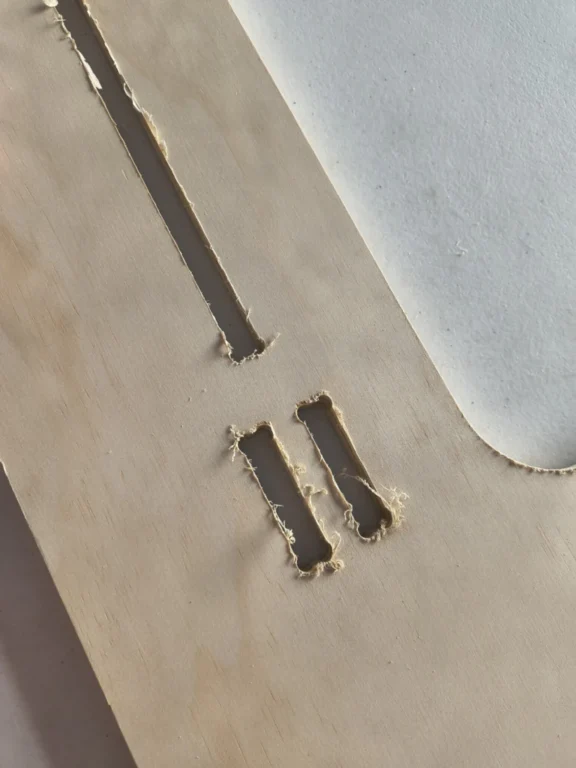
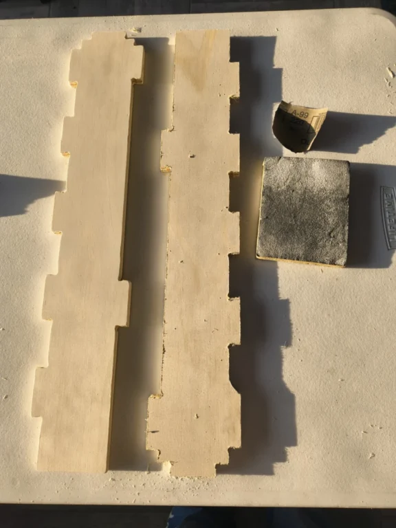
Generating the toolpaths in Vcarve (here we selected the tool type, the feeds and speeds, the depth and passes and added tabs to keep the pieces attached)
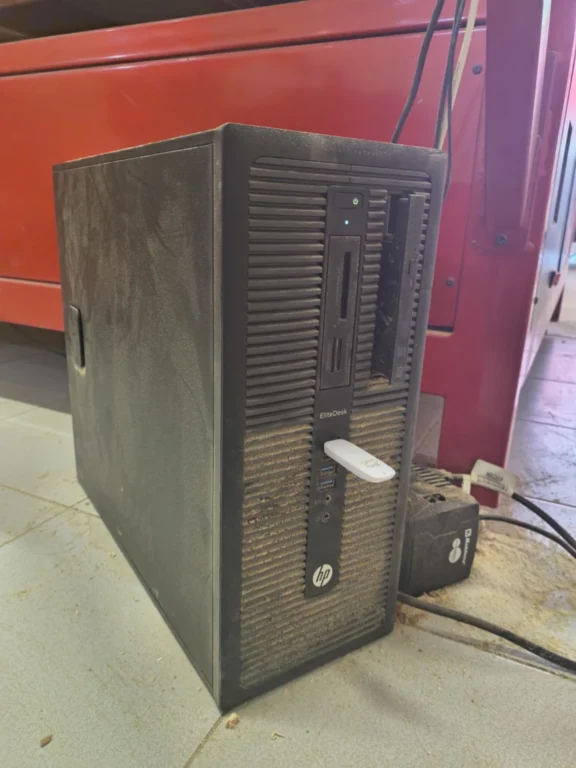
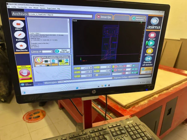
Exporting the G-code that is compatible with the CNC machine (this case a Mach 2/3 Arcs file .txt)
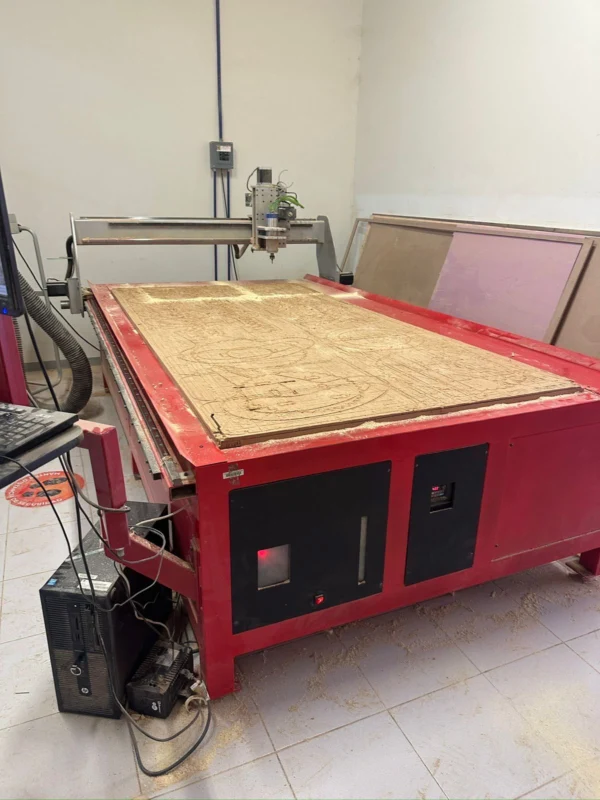
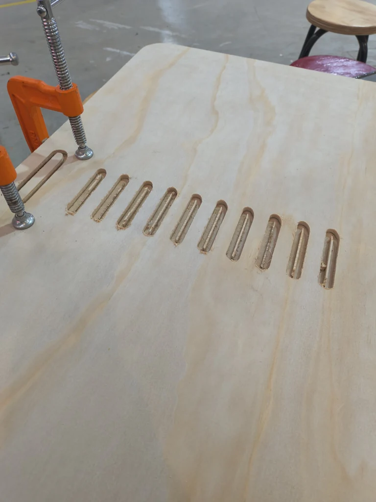
Setting up the Machine by securing the material (plywood) and setting the X,Y,Z origins.
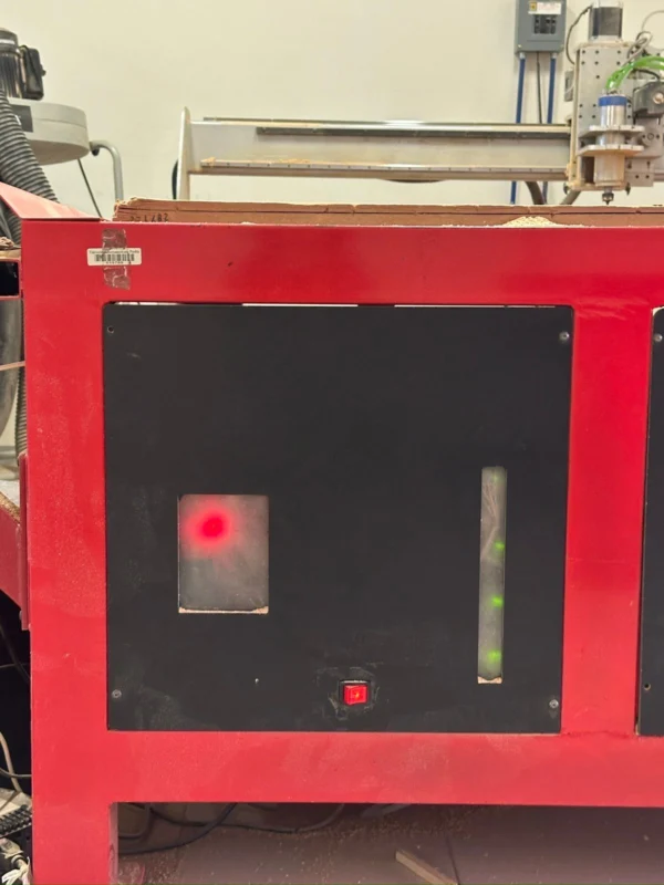
Running the job, monitoring it, and removing the dust.
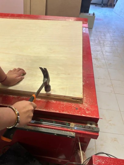
Post-processing wich includes sanding and assembling.
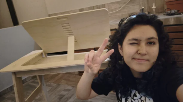
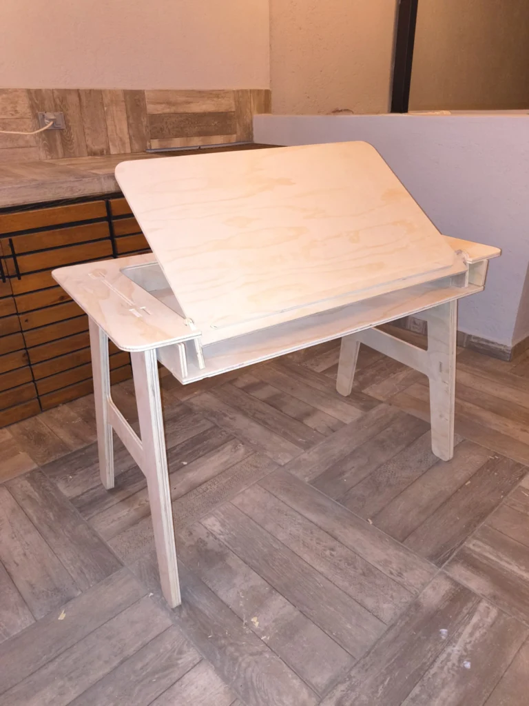
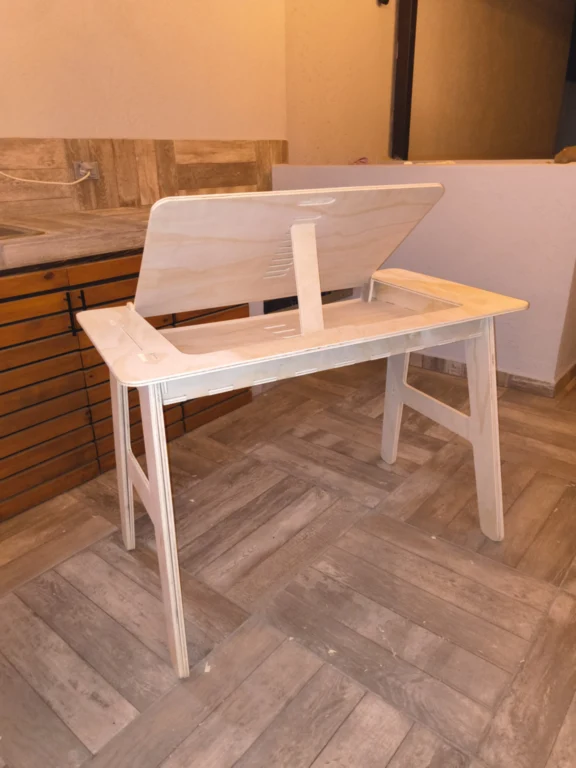
To know more about this check the group assignment:
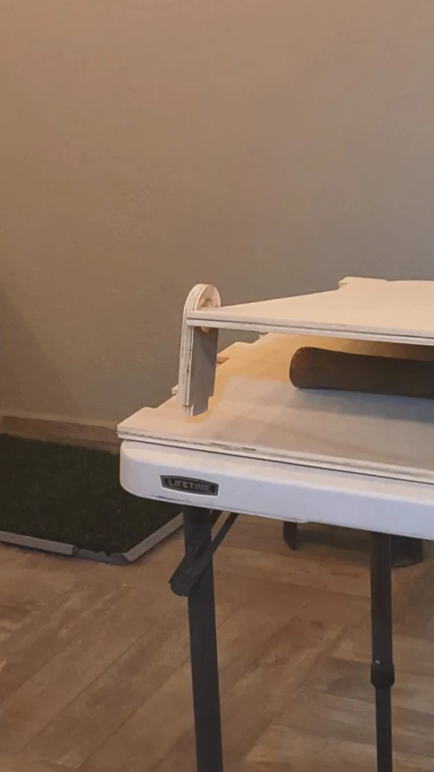
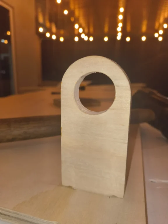
For this week I decided to do a press-fit drafting table, because it will help me a lot for when I'm drawing. It works with manual pivot and lock system,
inspired from this desing
, this way I don'tt use screws or metal hinges, just the plywood. Here you can explore my process:
3D Modeling in Onshape
To model the desk I used parametric variables, extrusion and boolean tools. After one piece was done I used it as reference for the next one. In total I had 17 pieces.
Here is a video that shows how I modeled it.
And here is an assembly of how the table works.
Generating a G-code in VCarve
1. Open VCarve and select open an existing file.
2. Select the DXF file of your pieces.
3. The default material panel will appear. Here we will edit the size of our job's workspace, and the origins .
The size I selected was a Length (x) of 1220 mm, Height (y) 2440 mm and a Width (z) of 12 mm.
4. With the command M, I moved my pieces, then I rotated them to fit the workspace. For the missing pieces I will repeat the procress an create a different toolpath for another plywood board.
5. Then I selected the Join Vectors tool, that will close all the open vectors I have (this is important for the next step).
6. Select the "Create Fillet" tool, and select the dog-bone fillet.
Apply the fillet to the internal edges, these will help us in our assembly process.
7. Select the vector of the toolpath you want to create, and select profile toolpath.
6. Go to file and select export in SVG.
Fixing error: One path was merged with another of a different color. So I used the scissors tool (C) to cut and separate them
6. Once they were different paths I change the ear outline to its correct color. Now the vector is ready to export.
Cutting plywood on a CNC router
For this exercise, this was the router we used.
2. First we need to turn it on.
3. Then we turned on the PC, and added a usb with our file (March 2/3 Arc .txt)
4. We open our file, and we will see the toolpaths. But before running the program we need to set the x,y,z origins.
For the Z, I moved the tool to the center and moved the Z axis until it touched my material. Once it was done, I set it as my zero, then moved it upwards.
After that, I moved the tool to the right bottom corner, to determine my x and y. Once it was adjusted I set them as my origin. I liberated the mergency button and start the cut.
Here is a video of how it runned
3.3 Change the parameters to your necesities
4. Move the image trace parameters to your necesities, I chose the color mode and moved the advanced features to my liking. Then clicked expand.
If you rasterized, the results will change a little (have less fidelity to the original image, in this case it colored the ear outline with yellow, but can be fixed)
5. After expanding, you have your vectorized image. (This was the result without rasterizing, ready to export).
6. Go to file and select export in SVG.
Fixing error: One path was merged with another of a different color. So I used the scissors tool (C) to cut and separate them
6. Once they were different paths I change the ear outline to its correct color. Now the vector is ready to export.
Snading, Fixing mistakes and assembling
1. Once our pieces are cutted, we need to sand them because of the wood shavings.
Here is the difference between two pieces
2. Somewhere in my toolpath procress I omitted two joints for the pivots of the table, and I realized after cutting the pieces so I ended up doing by hand.
To do so, I took the reference measures from my CAD model, the I troce the section to be removed and with a chisel & a hammer, I started removing the material, until I had a hole.
Then with a bastard file, to remove material and even the cut.
With that I could join the pieces together.
Another issue I found, was that I didnt configure correctly the nocth.
So I ended using a chisel, and sanded the are afterward.
Here is a speed video of how I joined the pieces, because I usse 0 tolerance and the wood was a little bit warped, some joints were to tight, so with the file I removed material and with the hammer I applied force.
This was the final result.
For large batches I prefer XnConvert, even if I need to share them back and forward between my computer (Phone Link is pretty fast and XnConvert has more resize parameters). However for single files on my computer that I need fast, I use the Photos app.
Learning Outcomes
This week helped me understand that digital design is not only about creating shapes, but designing with intention.
Vector precision is not automatic:
Achieving a faithful vector can be tricky and time-consuming. Image tracing tools are helpful, but they do not always produce clean geometry.
I learned that sometimes it is better to manually redraw vectors to have full control over curves and anchor points.
Dominating parameters takes practice:
Working with parametric tools requires understanding constraints and relationships between dimensions. It can be difficult at first to structure variables correctly, but once defined properly, we can have an iterative designs.
Different CAD environments, different strengths:
I did not struggle much transitioning between Onshape and Inventor because their interfaces are similar.
However, Inventor offers more advanced tools like rendering, while Onshape is excellent for cloud-based modeling and accessibility.
File compression and optimization:
I learned that large files can slow down the webpage and sharing processes. So by compressing files properly we can reduce file size without losing a lot of quality.
This is especially important when uploading our documentation. The biggest challenge for me was using FFMPEG to compress videos, but with some practice I undersanted how to use it.
This knowledge will help me trough my Fab LAB journey,as the fundamentals to document and model for my final project. Through this process I would like to learn how to use other CAD programms (Aside from Onshape I have worked with SolidWorks, Rhino, Fusion 360 and Blender, but have limited knowledge).