11. Networking and Communications
This week's assignment is to design, build, and connect wired or wireless node(s) with network or bus addresses and a local interface. I used this task as the base for the Smart Pill Dispenser which is a modular system built around a custom PCB for the XIAO ESP32-C6. It combines an RTC clock (DS3231), an OLED display, and a Wi-Fi web interface (HTTP), all communicating over the I2C bus and served through the microcontroller's built-in Wi-Fi Access Point. The general workflow for the project was:
- Build an I2C hub board: A small PCB that splits one I2C connection into multiple outputs so the RTC and OLED display can share the same two signal wires.
- Connect the RTC and OLED display: Wire the DS3231 real-time clock module via I2C (SDA/SCL), run an I2C scanner to confirm detection, and verify time-reading functionality. Repeat the test code with the OLED display.
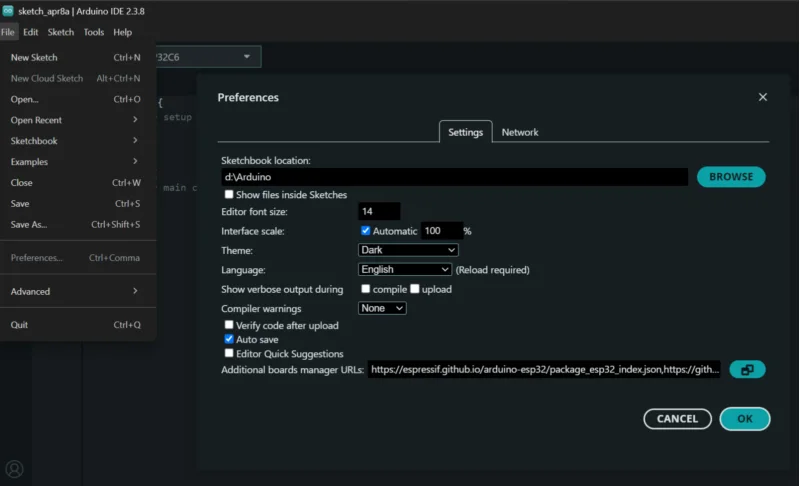
- Write the base code: Create an Arduino sketch that reads the time from the RTC clock and displays it on the OLED screen.
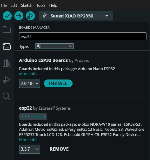
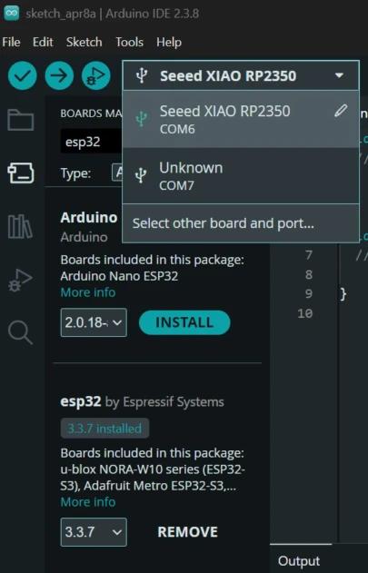
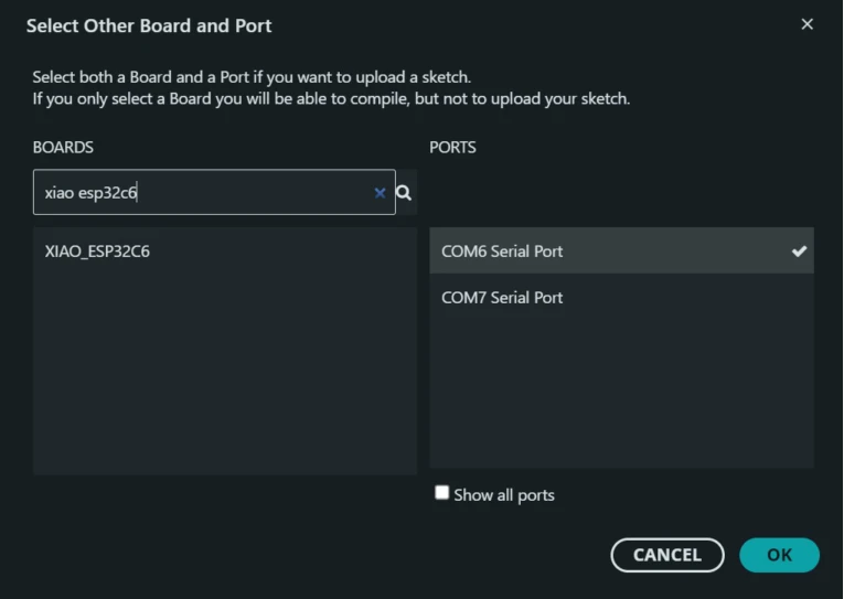
- Set up Wi-Fi Access Point: Configure the XIAO ESP32-C6 to broadcast its own Wi-Fi network (like a mini router), and create the HTTP interface.
- Solve hardware and software bugs: Debug issues like double pull-up resistors, wrong I2C pins, incorrect libraries, refining the system at every step.
What is Networking and Communications?
In electronics and embedded systems, networking and communications refers to the ways microcontrollers and other devices exchange data with each other or with the outside world. Think of it like spoken language: each protocol is a different language with its own rules about who speaks first, how many wires are needed, how fast data travels, and how far it can reach.
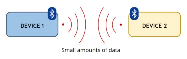
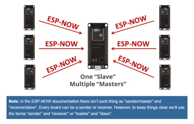
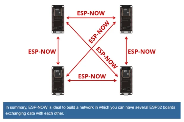
This week we explored how our microcontrollers can "talk" to sensors or other boards (even to other devices like phones or laptops), either through physical wires or wireless connections through radio signals. Some of the existing protocols are I2C, SPI, UART, Wi-Fi, Bluetooth, ESP-NOW, HTTP, MQTT, and many more. Each has its own advantages and disadvantages depending on the use case. To learn more about them check the group assignment.
I2C: Inter-Integrated Circuit
I2C is a two-wire serial bus: SDA (Serial Data-transports the info) and SCL (Serial Clock-Synchronizes the data transmission), plus a shared ground. One device is the host (usually the microcontroller) and others are the targets with a unique 7-bit addresses.
The host or controllersends a START signal, then the address of the device it wants to talk to, then the data, and finally a STOP signal. Every device on the bus listens, but only the one with the matching address responds. This is why you can connect many devices to the same two wires.
Advantages
- Only 2 wires needed regardless of how many devices
- Many devices can share the same bus (each has a unique address)
- Simple wiring, great for sensors and displays
Disadvantages
- Slower than SPI (up to ~400 kHz standard)
- Short distances only (same PCB or a few cm)
- Address conflicts if two devices share the same address
- Pull-up resistors required on SDA and SCL in some cases
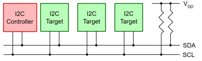
I2C bus: one host, multiple targets, only 2 signal wires.
Real-world examples
OLED displays, RTC clocks, temperature sensors (BME280), IMUs (MPU-6050), EEPROMs. This is the protocol I used this week to connect the RTC (DS3231) and the OLED display to my ESP32-C6 PCB.
Smart Pill Dispenser: My Week 11 Project
Designing the hub board
I designed a signal distribution board in KiCad. This board breaks out the I2C lines (SDA, SCL, VCC, GND) to multiple headers so I can connect both the RTC and the OLED display to the same bus. The idea is that this board will serve as a modular "hub" that can be reused in future projects where I need to connect multiple I2C devices to an ESP32-C6, without needing to redesign the PCB every time.
The PCB production process follows the same steps as Week 08 (Electronics Production):
1.Schematic and PCB editor in KiCad
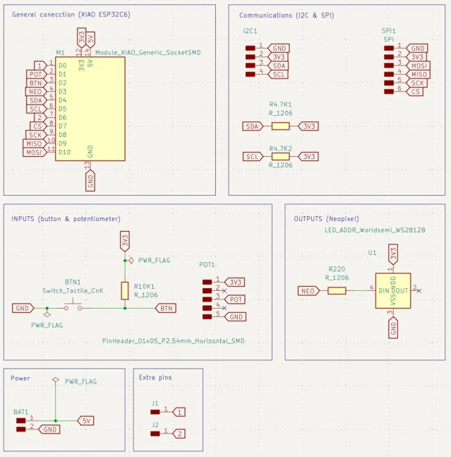
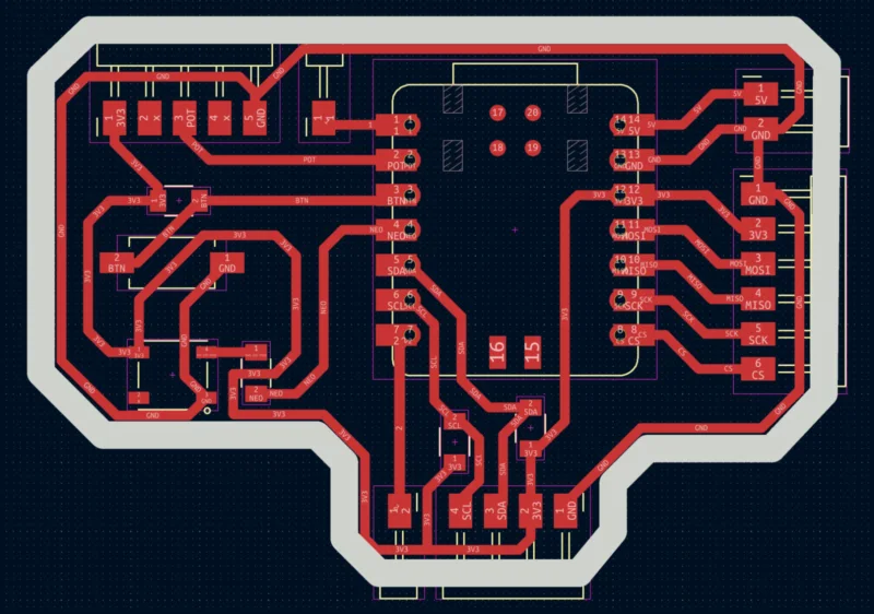
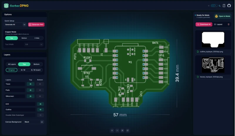
I used the schematic editor to create the circuit diagram, it consist four 4-pin vertical headers , that share the then I2C header pins (SDA, SCL, VCC, GND). After that used the PCB editor to place the components and route the traces (with a minimun track with of 1 mm). Once the traces and edge cuts were done, I exported them in Gerber files.
2. Gerber to PNG
I used Gerber2PNG to convert the files into PNG format as it is required by the Mods page. I dowlaoded all the PNG files (drills, traces and outline).
3. Mods Project to RML
I used Mods project to generate the RML toolpaths for the SRM-20, setting x,y,z to 0,0,0 and configuring traces, outline, and drills for each layer.
The settings I use are:
- Traces for the engraving pass: 6º #V-bit tool, 0.4 mm tool diameter, 0.1016 mm cut depth with 4 offsets. And a speed of 4 mm/s.
- Outline (board edge): 1/16 cutout tool, 1.6 mm tool diameter, 0.6096 mm cut depth and a 0.6096 mm max depth. And a speed of 4 mm/s.
- Drills for through-hole: 1/32 drill tool, 0.8 mm tool diameter, 0.254 mm cut depth, 1.7018 mm max depth. And a speed of 0.2 mm/s.
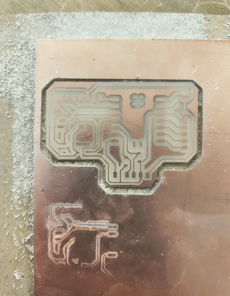
4. Milling on the Roland SRM-20
Once the RML files were generated, I loaded them into the Roland SRM-20 software and set up the milling process. I had to secure the PCB material properly on the milling bed and ensure the each tool was correctly zeroed before starting the milling. The order of milling was: first the dills, then the traces, and finally the outline.
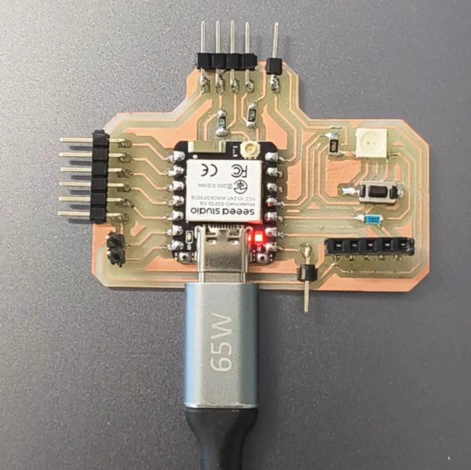
5.Soldering
The fabrication process was simple, I added the pin headers and soldered them one by one.
6. Connecting the components
Once it was soldered, I used jumper wires to connect the RTC and OLED to the hub board and onthe PCB with the XIAO ESP32-C6. The connections are were: SDA to D0 and SCL D1, VCC to 3.3V, and GND to GND.
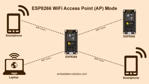
Wi-Fi Access Point and Web Interface
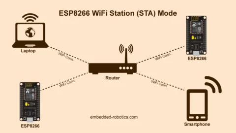
The final layer of the project is the web interface for the pill dispenser. The XIAO ESP32-C6 creates its own Wi-Fi network (Access Point mode) so the user can connect from any phone or laptop without needing an internet router. The built-in web server then serves an HTML/CSS interface at a fixed IP address (192.168.4.1).
How Access Point Mode Works
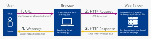
In AP mode the ESP32-C6 behaves like a mini router. It broadcasts a Wi-Fi network with a name (SSID) and optional password. When you connect to it and open a browser to 192.168.4.1, the microcontroller receives the HTTP request and sends back the web page. No internet connection required.
Possible Improvements
- Connect to home Wi-Fi (Station mode). Currently the device runs in AP mode and creates its own network. A future version could connect to the home router, enabling real push notifications (like sending a message to the user's phone when it is time to take a pill) and cloud logging.
- Alarm groups and medication types. The current interface has a single alarm. The next version would allow multiple alarms organized by medication name or group (morning pills, evening pills), with different alert sounds for each.
- Integrate servo and passive buzzer. The servo from Week 10 would physically actuate the dispenser compartment, and the passive buzzer would play an alert tone at alarm time. Both were tested individually in Week 10 and are ready to integrate.
Learning Outcomes
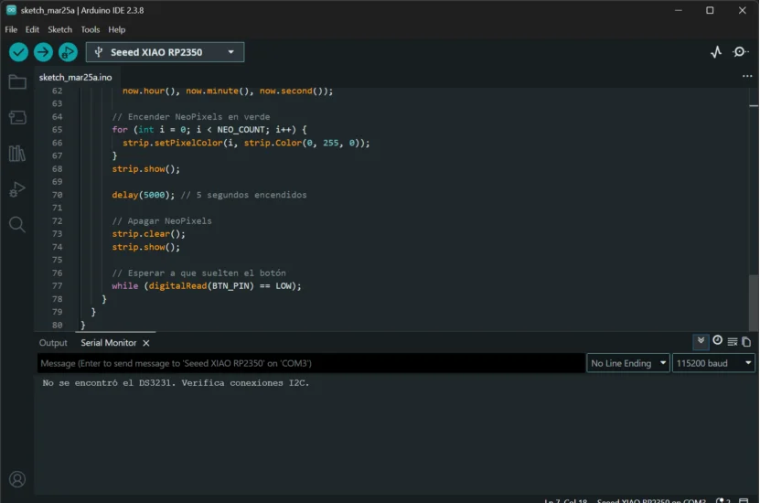
- Always run an I2C scanner first. Before writing any application code, confirm the device responds on the bus using a scanner sketch. If nothing is found, the problem is in the wiring or hardware, not the code. This saves hours of debugging the wrong layer.
- Pin assignments must be verified in hardware: I assumed SDA/SCL were on D4/D5 based on a generic diagram. The actual hardware I2C peripheral on the XIAO ESP32-C6 lives on D0/D1. When a device does not respond, swapping to a different pair of pins is one of the first things to try.
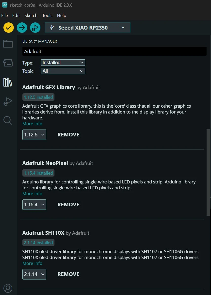
- Library choice is critical for displays: use the right one from the start. Several different libraries exist for the SSD1306 OLED, and they are not interchangeable. Using the wrong one will compile without errors but produce no output, making it a frustrating bug to find. For this chip, always use Adafruit SSD1306 together with Adafruit GFX.