10. Output Devices
This week's individual assignment is to add an output device to a microcontroller board and program it to do something. I chose to document two output devices that are directly relevant to my final project:
- A passive buzzer (for audio feedback and melodies)
- A micro servo motor (for small actuation)
For full power consumption measurements, check out the group assignment.
Group Assignment.
What are Output Devices?
An output device is a component that takes an electrical signal from the microcontroller and converts it into a physical effect. It can produce movement (motor), light (LED), sound (buzzer), or an image on a screen (display). They work along with input devices to create interactive systems: the microcontroller reads data from sensors (inputs), processes it and transform it into a effect in the real world (outputs).
To measure the power consumption of the output devices, we used a USB tester connected in series with the power supply. This allows us to see how much current (in Amperes) the device draws at different states, and since we know the voltage (in Volts), we can calculate the power (in Watts) using the formula P = V × I.
Buzzer + Servo Motor
For this week I chose to program a buzzer and a servo motor at the same time, simulating the alarm sound and movement when the button is pressed. The buzzer is a passive one, which means it can produce different tones depending on the frequency of the signal sent to it, unlike an active buzzer that just turns on or off. The servo motor is a micro servo (SG90) that can rotate to a specific angle based on the PWM signal it receives.Designing the Modular ESP32-C6 PCB
For Inputs & Outputs week, I wanted to create a custom PCB that would allow me to easily connect the XIAO ESP32-C6 microcontroller with various sensors and output devices for future projects. The PCB production process follows the same steps as Week 08 (Electronics Production)
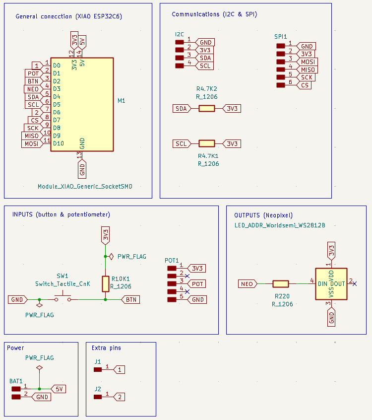
1.Schematic in KiCad
I drew the schematic placing the XIAO ESP32-C6 footprint at the center, then added I2C header pins (SDA, SCL, VCC, GND) for connecting external devices like the RTC and OLED. I also included SPI header pins (MOSI, MISO, SCK) for future expansion with devices like SD cards or displays. I also included a WS2812B NeoPixel with a 240 Ω resistor and a button with a 10 kΩ resistor for testing.
2. PCB Layout and Routing
After placing all footprints I routed the copper traces with a minimum clearance of 0.5 mm and a minimum track width of 0.7 mm. Routing without cutting the paths was a bit tricky but I managed to fit everything in a 60x46 mm board.
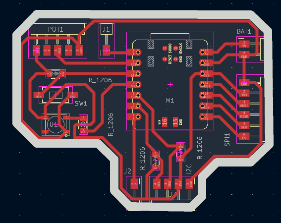
Here and in the schematic I used the rule checker to find any errors and make sure all connections were correct. Some common errors were related to clearance violations and incorrect power connections.
3. Gerbers to PNG
Once done, I exported the Gerber files. And used Gerber2PNG to convert them to PNG format as it is required by the Mods page.
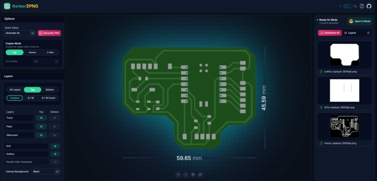
I saved both the outline and the traces as separate PNG files, which I then loaded into the Mods project page to generate the tool paths for milling.
4. RML files generation on Mods
I uploaded the PNG files to Mods, selecting the SRM-20 mill configuration and assigned the correct settings for each layer, all in x,y, z cordinates in 0,0,0.
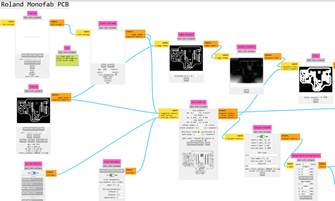
The settings I use are:
- Traces for the engraving pass: 6º #V-bit tool, 0.4 mm tool diameter, 0.1016 mm cut depth with 4 offsets. And a speed of 4 mm/s.
- Outline (board edge): 1/16 cutout tool, 1.6 mm tool diameter, 0.6096 mm cut depth and a 0.6096 mm max depth. And a speed of 4 mm/s.
- Drills for through-hole: 1/32 drill tool, 0.8 mm tool diameter, 0.254 mm cut depth, 1.7018 mm max depth. And a speed of 0.2 mm/s.
Step 5: Milling on the Roland SRM-20
The board was milled on the Roland SRM-20 Mini Mill at Fab Lab Puebla using the RML tool paths generated from Mods.
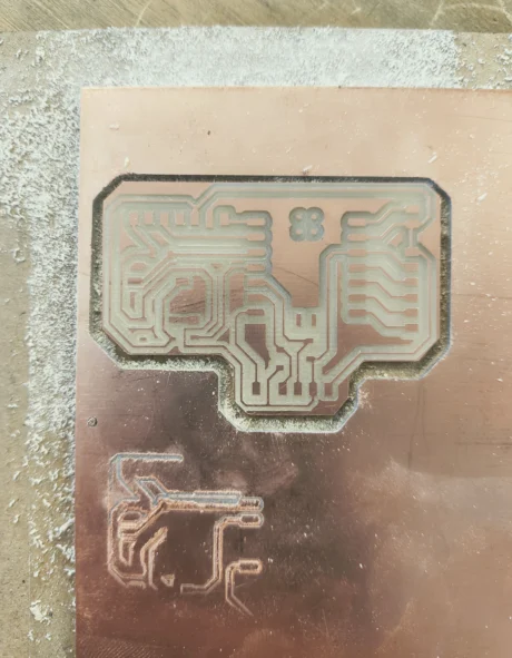
Some issues I encountered were related to the zeroing of the tool and the flatness of the PCB material, which caused some traces to be cut too deep and others not deep enough. I had to adjust the z-zero point and run the milling process twice to get clean traces without cutting through the board.
Step 6: Soldering All Components
First I soldered the SMD resistors (1206), the pin headers, then the WS2812B NeoPixel and lastly the XIAO ESP32-C6 module. Its important tto cover the bottom of the board to prevent short-circuits.
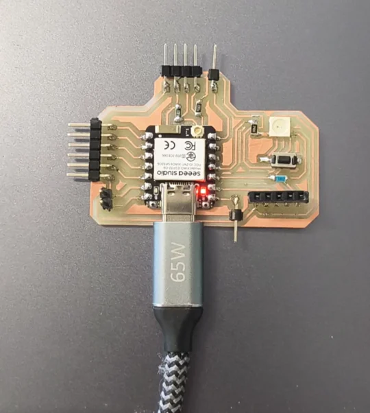
After soldering, I tested continuity with a multimeter to confirm all connections were correct, however there was no continuity on the Neopixel connections, tried desoldering and resoldering it but it seems to be damaged, so I removed it from the circuit and tested the rest of the connections, which were all correct.
Programming the Buzzer and Servo
I programmed the buzzer and servo using the Arduino IDE. The code is structured to play a melody on the buzzer and move the servo to specific angles when a button is pressed. I used manual PWM generation for the buzzer since the tone() function is unreliable on this microcontroller.
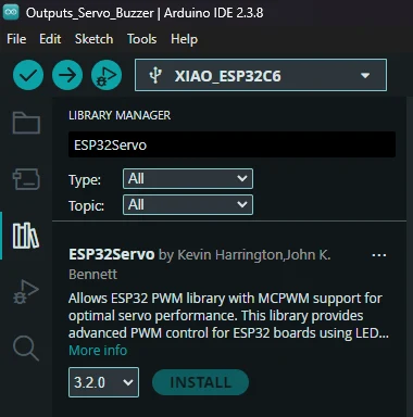
1. Installing the ESP32 Servo Library
In Arduino IDE, go to Sketch select Include Library and click on Manage Libraries then search for ESP32Servo. Install the one by Kevin Harrington. This library provides proper PWM servo control for ESP32 boards.
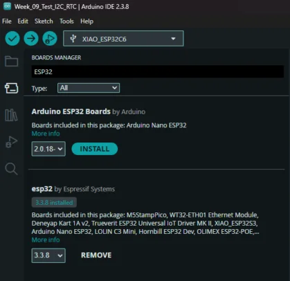
2. Adding the ESP32-C6 Board
Go to File select Preferences and add the board URL to the
Additional Boards Manager URLs field: https://raw.githubusercontent.com/espressif/arduino-esp32/gh-pages/package_esp32_index.json
Then go to Tools select Boards Manager, and search for
esp32 install the package by Espressif Systems. Then select XIAO_ESP32C6 from the boards list.
Learning Outcomes
This week I learned how to program different output devices and its power consumption, thanks to the group assignment. While in my individual work, I learned how to combine two output devices in a single circuit.
- Passive buzzer vs Active buzzer: The passive buzzer is perfect for audio alerts when it's time to take a pill, as it can play distinct tones per alarm. It also requires extremely low power (≈0.1 W), while the active buzzer just produces a fixed tone.
- Power consuption is important: Measuring the current draw of the buzzer and servo at different states helped me understand how much power each component consumes, which is crucial for battery life in the final product. The micro servo draws more current (up to 0.1 A) when active compared to the buzzer (≈0.03 A).
- Modular design success: Learned how to combine multiple output devices (passive buzzer + micro servo) in a single circuit controlled by one microcontroller, coordinating their actions simultaneously through a single button press. Its important to now which pins are being used and which are used for specific functions (like PWM for the servo) to avoid conflicts and ensure proper operation.