14. Interface and Application Programming
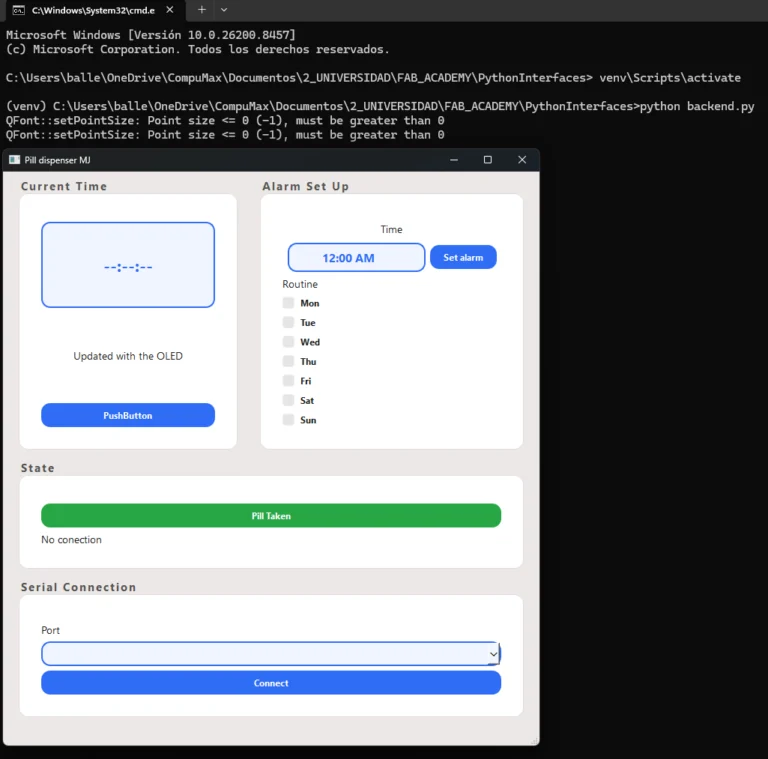
This week's assignment was to write an application for a embedded board that interfaces a user with an input and/or output device. I decided to build a pill dispenser desktop app that communicates over Serial with a XIAO ESP32-C6. The app shows the real time read from a DS3231 RTC directly on the screen, letting the user set an alarm with a specific time and choose which days of the week it should trigger. And when that alarm fires it activates a passive buzzer and a servo motor on the board to physically dispense a pill. I built the interface in Qt Designer and wrote the logic in Python using PySerial for the Serial connection.
The general workflow this week was:
- Learning the basics of Qt Designer and how to connect it to Python code.
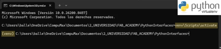
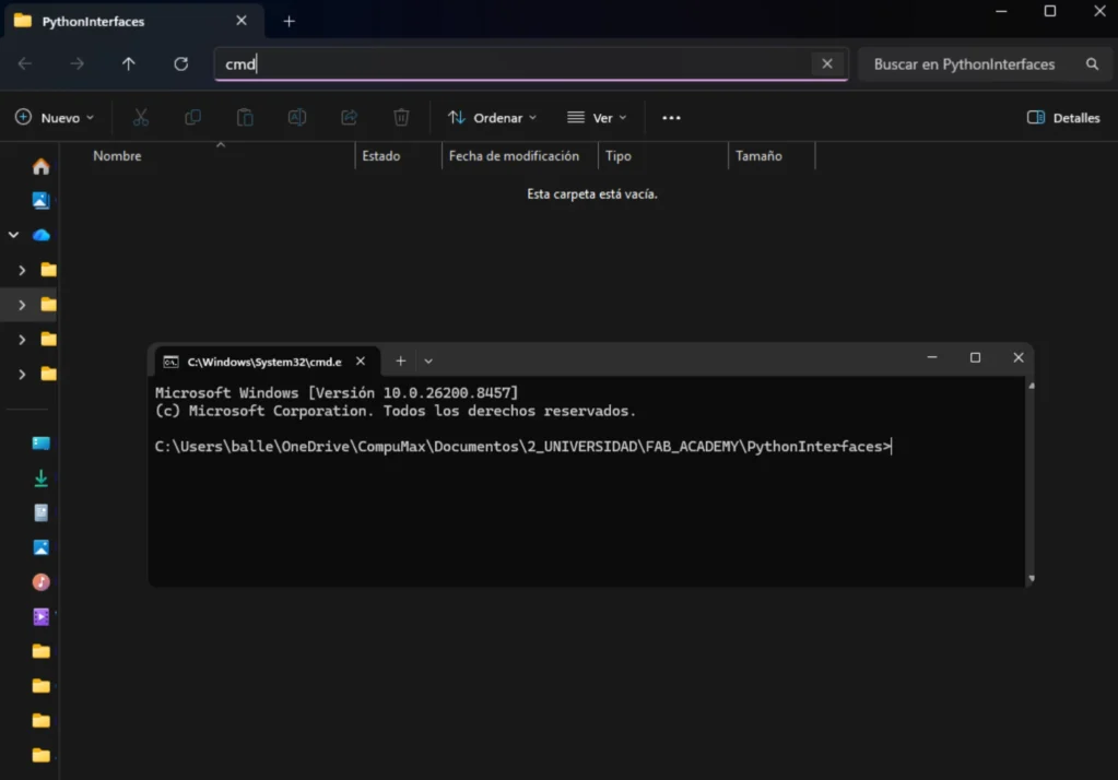
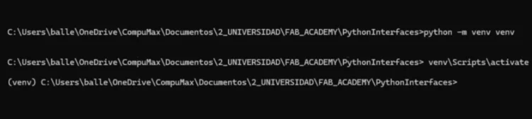
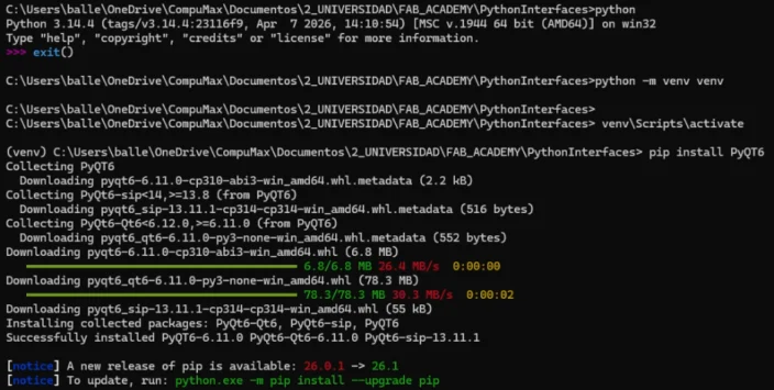
- Setting up a Python virtual environment with the required libraries.
- Designing a custom serial communication protocol between the app and the XIAO ESP32-C6.
- Writing backend.py with a serial worker thread and all the UI logic.
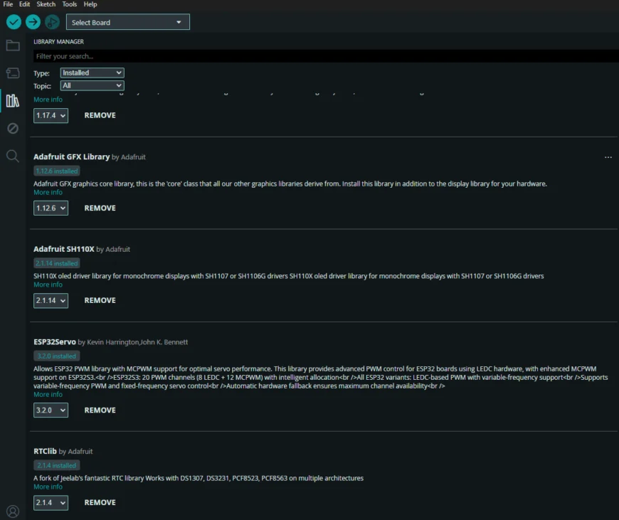
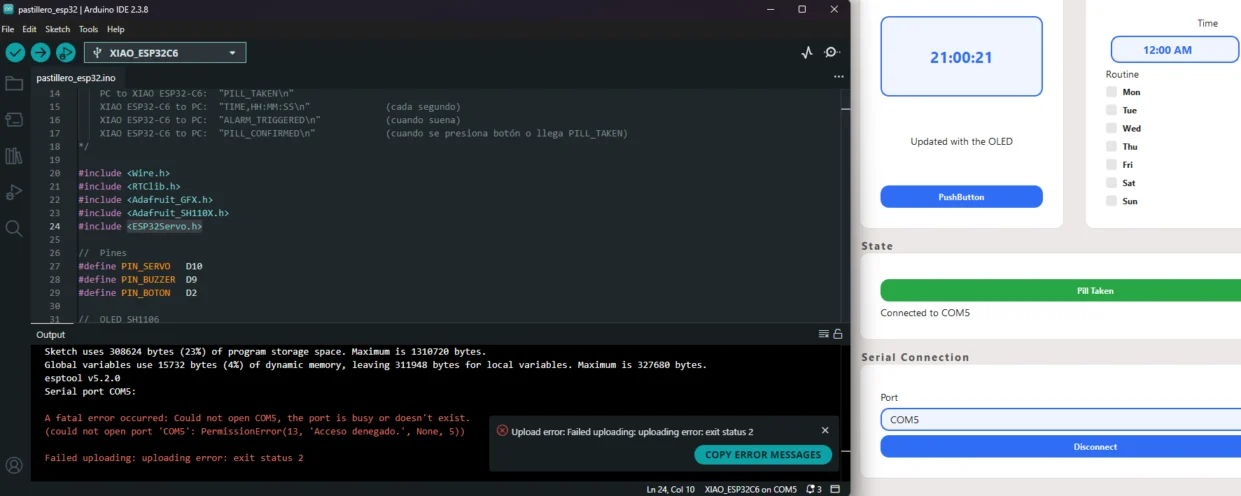
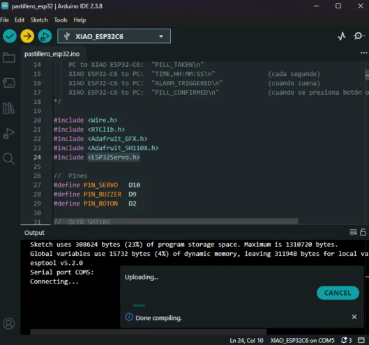
- Writing the XIAO ESP32-C6 firmware to parse commands, drive the servo, buzzer, and OLED.
- Connecting all the hardware and testing the full system end-to-end.
Key Concepts
What is Qt Designer?
Qt Designer is a visual tool for building graphical user interfaces (GUIs) without writing layout code by hand. You drag and drop widgets (buttons, labels, line edits, checkboxes, etc.) onto a canvas and arrange them visually. When you save, Qt Designer generates a .ui file, which is an XML representation of the interface. This .ui file can then be loaded in Python to create the actual GUI at runtime, allowing you to iterate on the design quickly without touching the code until you are happy with the layout and look.
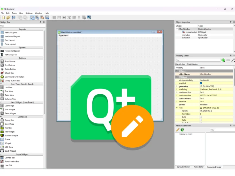
The main panels I used were the Widget Box, the Object Inspector, and the Property Editor. The most important property for connecting the interface to Python is objectName, because this is the name the backend code uses to reference each widget.
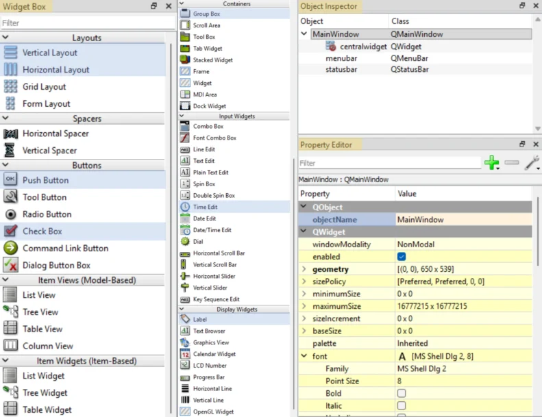
The main widgets I used were: Vertical and Horizontal Layout, Label, Group Box, Press Button, CheckBox and Time Edit
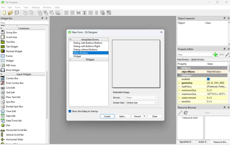
Step 1: Create the Main Window
I started by opening Qt Designer and creating a Main Window project. This gave me the base canvas where I could place the pill dispenser interface elements and organize the layout visually.
Step 2: Add the Main Widgets
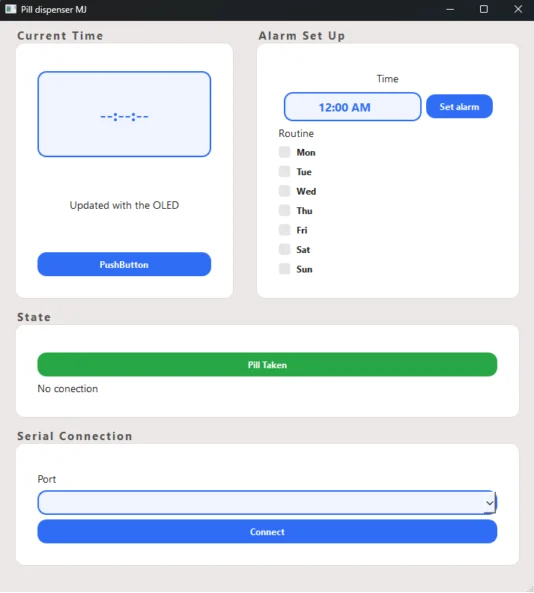
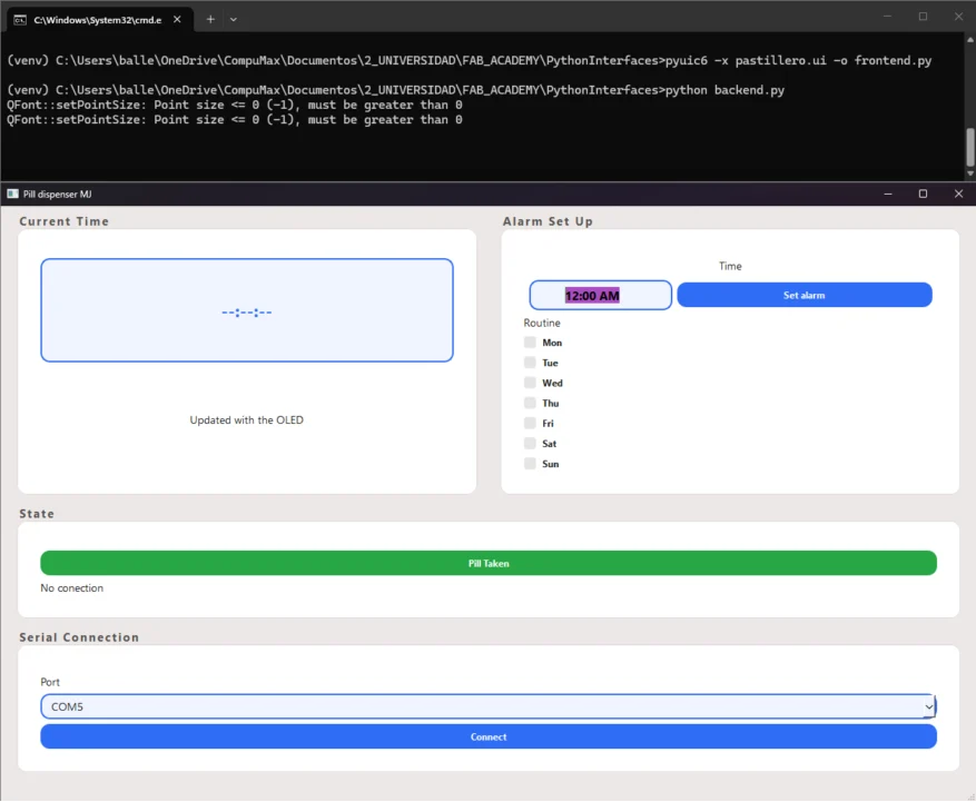
From the Widget Box, I dragged the interface elements into the window: labels for the current time and status, a time picker for the alarm, checkboxes for the days of the week, a port selector, and buttons for connecting, setting the alarm, and confirming the pill was taken.
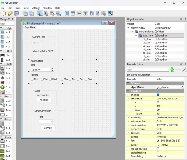
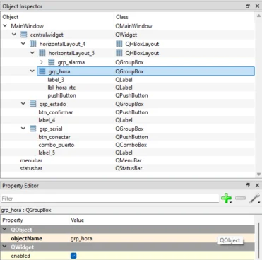
Step 3:Rename the Object Names
After placing the widgets, I renamed their objectName values in the Property Editor. This is important because the Python backend later calls widgets by name, such as self.portSelector, self.statusLabel, or self.btnPastilla.
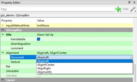
Step 4: Adjust Text, Size, and Layout
I edited the visible text, font sizes, spacing, and alignment from the Property Editor. This helped make the interface readable and clear, especially for the time display, alarm controls, and user feedback messages.
Step 5: Apply the StyleSheet
To style the whole app, I selected MainWindow in the Object Inspector, opened the styleSheet property, and wrote custom CSS-like rules for the window background, labels, inputs, and buttons.
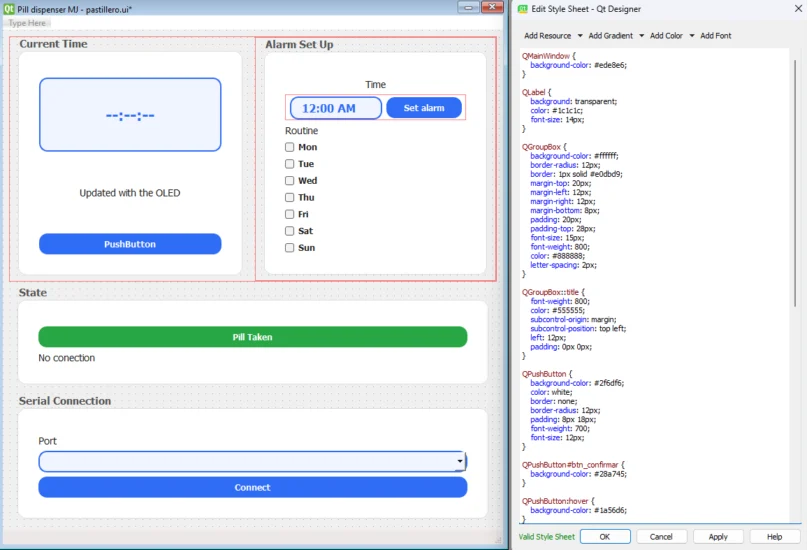
This will create a general CSS, however you can override specific styles for individual widgets.
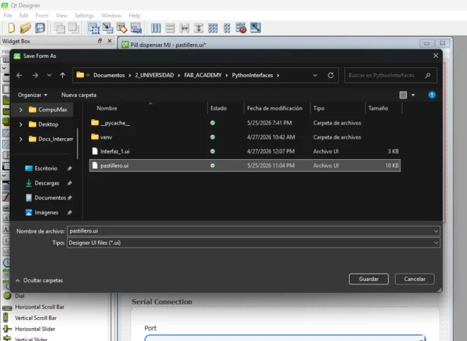
Step 6: Save the .ui File
Finally, I saved the interface as pastillero.ui. This file stores the complete visual design and is later loaded by the Python backend, so I can keep changing the interface in Qt Designer without rewriting the Python layout code.

Backend Code
This is the Python side of the project. It loads the interface generated from Qt Designer,
opens the Serial connection, listens for messages from the XIAO ESP32-C6, and sends commands when
the user sets an alarm or confirms that the pill was taken. In this section I will share the full code of backend.py and slides explaining the most important parts.
Learning Outcomes
This week helped me connect interface design, Python programming, Serial communication, and embedded hardware into one complete pill dispenser system. These were my main takeaways:
- Qt Designer makes interface building much faster: Designing the pill dispenser window visually helped me organize the time display, alarm controls, day checkboxes, port selector, and action buttons before writing the Python logic. Renaming each widget with a clear objectName was essential because those names are what backend.py uses to control the interface.
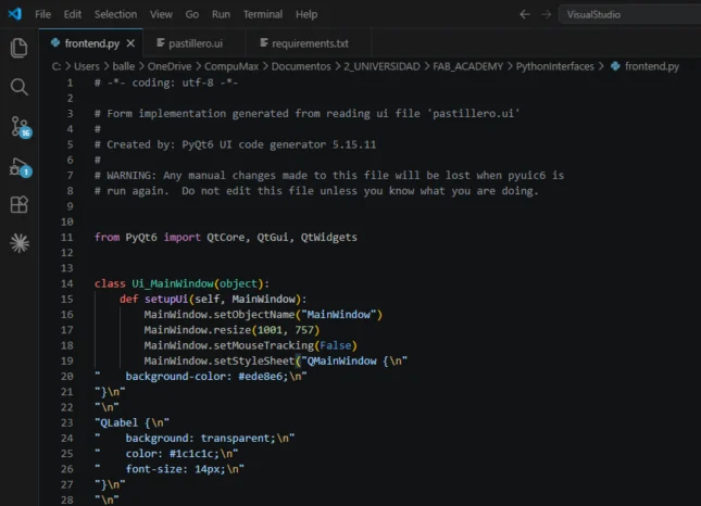
- Keeping the interface and backend separate makes the project easier to manage: I used Qt Designer to create pastillero.ui, converted it with pyuic6 into frontend.py, and kept the behavior in backend.py. This structure made it easier to update the visual design, connect buttons, read values from the widgets, and debug the app without mixing layout code with logic.
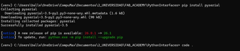
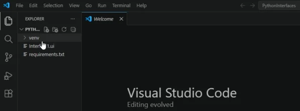
- A virtual environment keeps the Python project reproducible: Creating a venv and installing PyQt6 and pyserial inside it helped keep the app's dependencies organized. Saving the installed packages in requirements.txt also makes the project easier to recreate on another computer.
- Serial communication needs a clear protocol: Defining messages such as TIME, SET_ALARM, PILL_TAKEN, ALARM_TRIGGERED, and PILL_CONFIRMED made communication between Python and the XIAO ESP32-C6 predictable. Because every message had a specific format, both sides could parse commands and respond without confusion.
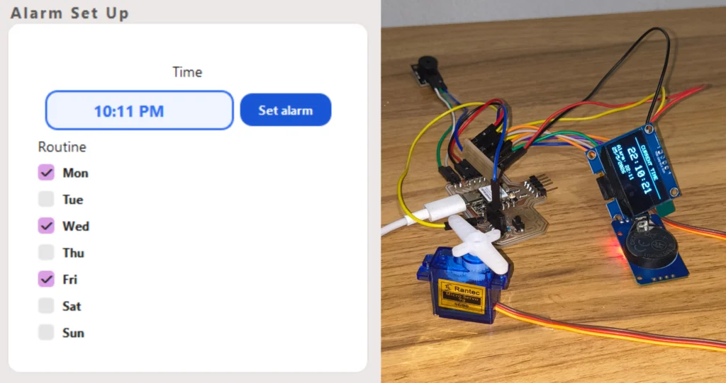
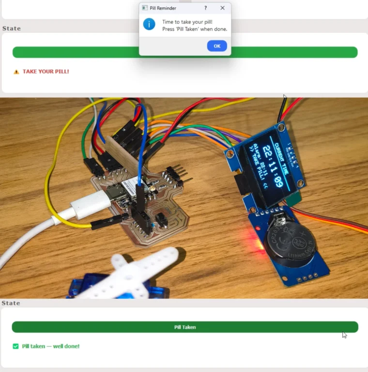
- The desktop app and firmware have to be tested as one system: The final behavior depended on many parts working together: the DS3231 RTC sending the time, Python displaying it, the user setting an alarm, the XIAO ESP32-C6 activating the servo and buzzer, and the confirmation message returning to the app. Testing the full chain helped me find problems that would not appear when testing each component alone.
- Threading is important for responsive interfaces: Reading Serial data continuously can block a program, so using a worker thread allowed the app to keep receiving messages from the board while the PyQt6 interface stayed usable and responsive.