The objective of this wildcard week was to design and produce something utilizing a digital fabrication process that incorporates computer-aided design (CAD) and manufacturing (CAM) which has not been covered in any of the previous academic assignments.
To make the most of this week, I decided to broaden my hands-on skills by experimenting with three distinct industrial and prototyping processes:
Sandblasting, Electroplating, and Thermoforming.
1. Sandblasting Process
What is it?
Sandblasting (abrasive blasting) is a surface-finishing technique where a high-pressure stream of abrasive material is forcibly propelled against a surface. It is commonly used to smooth rough surfaces, shape profiles, or etch patterns onto materials like metals, and plastics by wearing down the exposed areas.
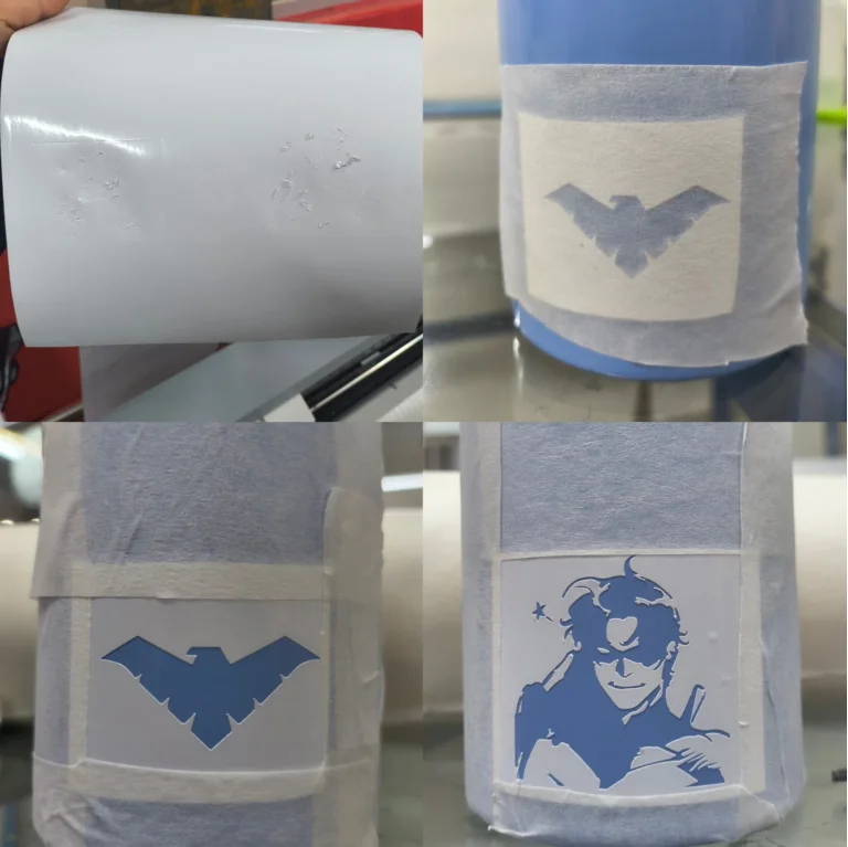
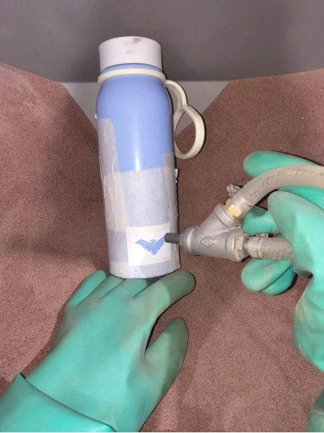
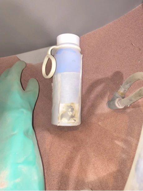
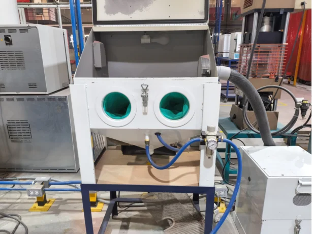
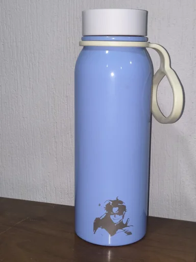
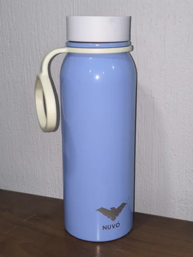
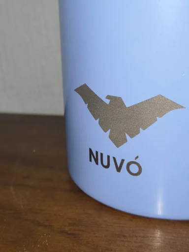
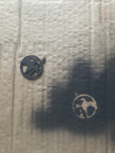
For this process, I created custom masks by vectorizing artwork in Adobe Illustrator and cutting adhesive vinyl masks using the Roland VersaSTUDIO GS2-24 cutter combined with Cut Studio software. These vinyl stencils were carefully applied onto a painted metal bottle before placing them inside the sandblasting chamber to achieve a engraved effect. Additionally, I ran an experimental test to investigate how sandblasting can be utilized to post-process and smooth out the layer lines of a raw FDM 3D printed parts.
Vectorizing
To obtain clean cutting paths for the vinyl machine, the original raster images needed to be translated into crisp vector geometries.
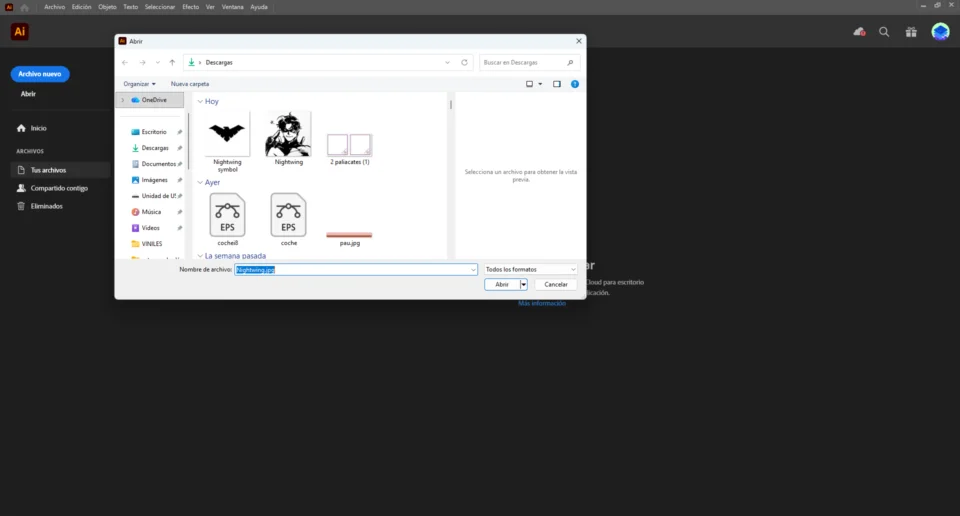
Step 1: Import an image directly into Adobe Illustrator by creating a new document.
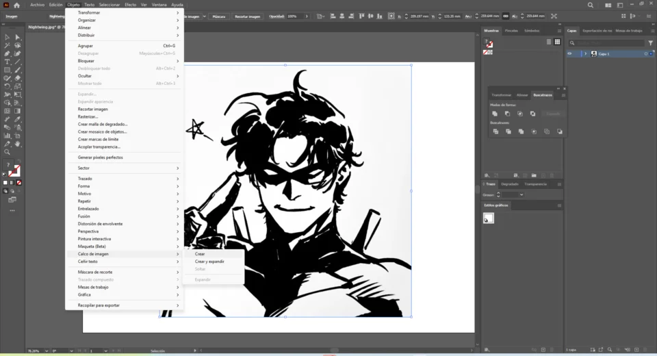
Step 2: Navigate into the tool bar, open the Object menu bar, open the Image Trace submenu, and click on 'Create' to begin processing the image into traces.
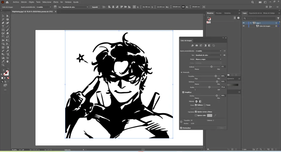
Step 3: Open the Advanced Image Trace Options panel to fine-tune the thresholds, paths, and corners until the preview lines match your target shape Once satisfied, click Expand to convert the live trace into editable vector vector paths and anchor points.
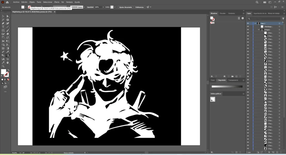
Step 4: Adjust the vector paths as needed and export the finalized graphic in a format compatible with your cutting software. In this case I inverted the color scheme to a negative version of the original, so when I sandblast the results is just like the original image.
Vinyl Cutter CAM Configuration
This phase consists of configuring our digital paths inside the software to generate the correct cutting lines and tool paths for the Roland vinyl cutter.
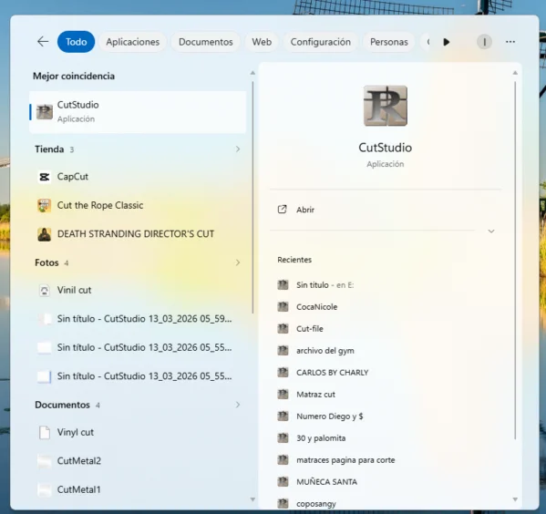
Step 1: Open Roland CutStudio workspace.
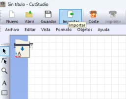
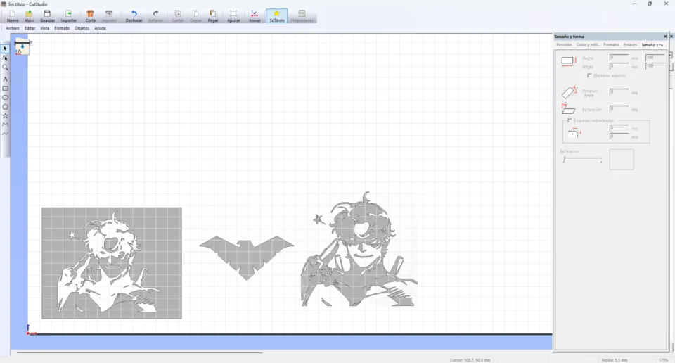
Step 2: Go to the tool bar menu and select Import, then choose the vectorized image.
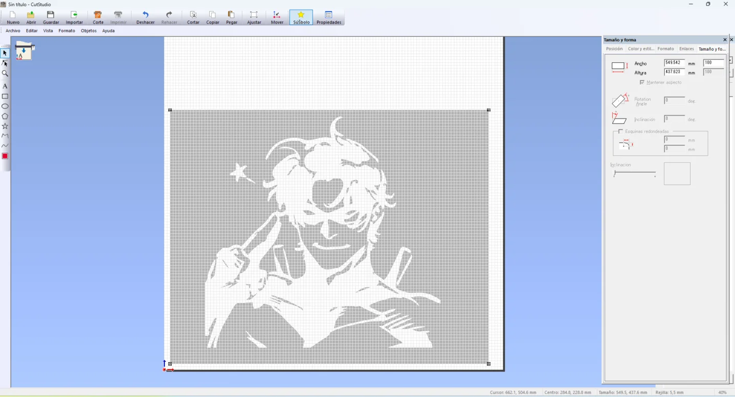
Step 3: Once the image is imported, modify its scale, so it has the desired dimensions.
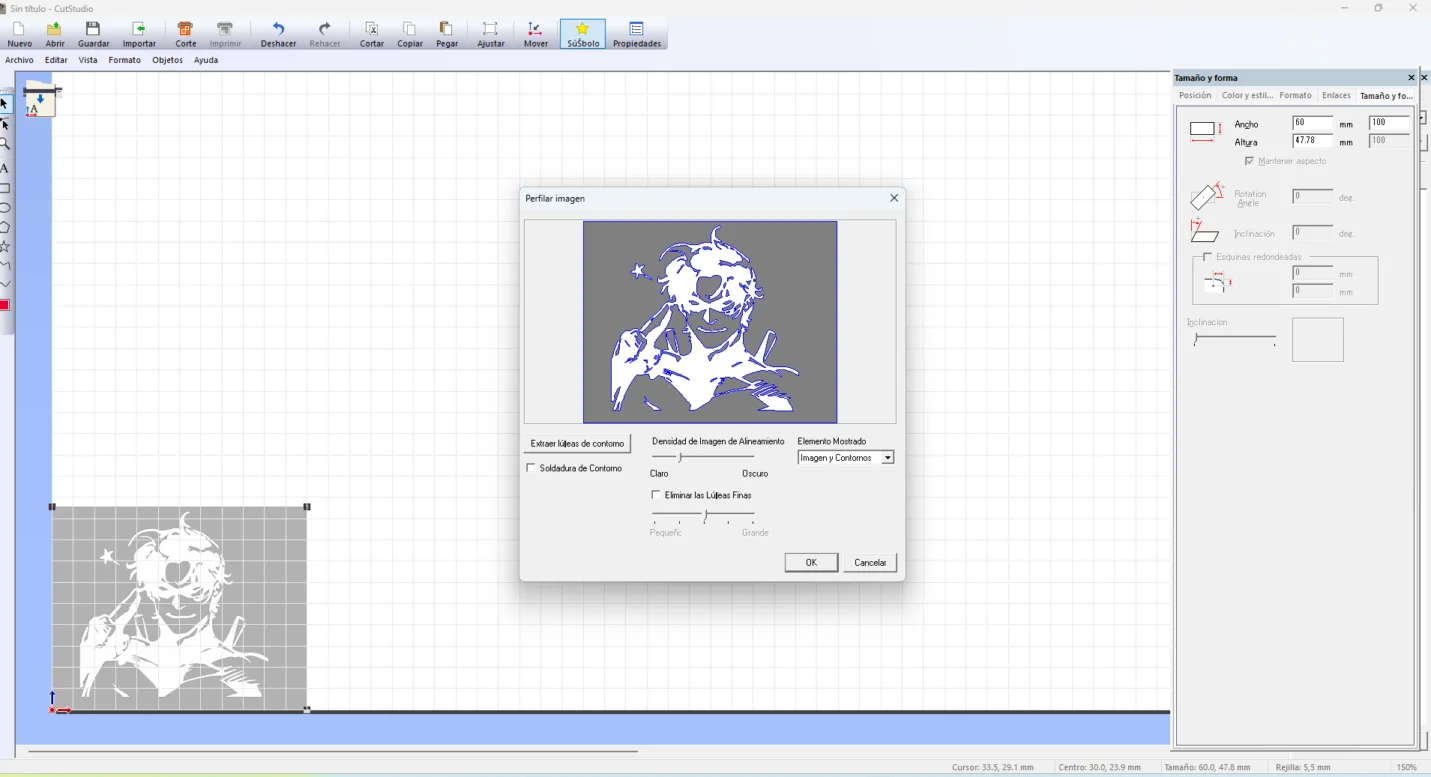
Step 4: Right-click on your image, select Trace outlines and click OK. This will generate the cutting lines for the vinyl cutter.
Step 5: Replicate for as many individual graphics you have. The first two are images y vectorized while the last one is the raw jpeg file. The main difference is that the vectorized images will have sharper cutting lines and will be easier to peel.
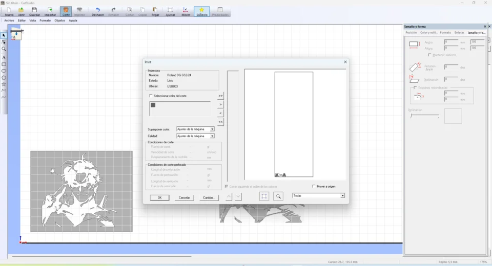
Step 6: Once the machine is ready and the design is properly positioned, go to the tool bar, select Cut, and hit 'OK'.
Vinyl Hardware Operation
Correctly feeding and fixing raw material roll stocks guarantees clean cutting performance without tracking alignment drift.
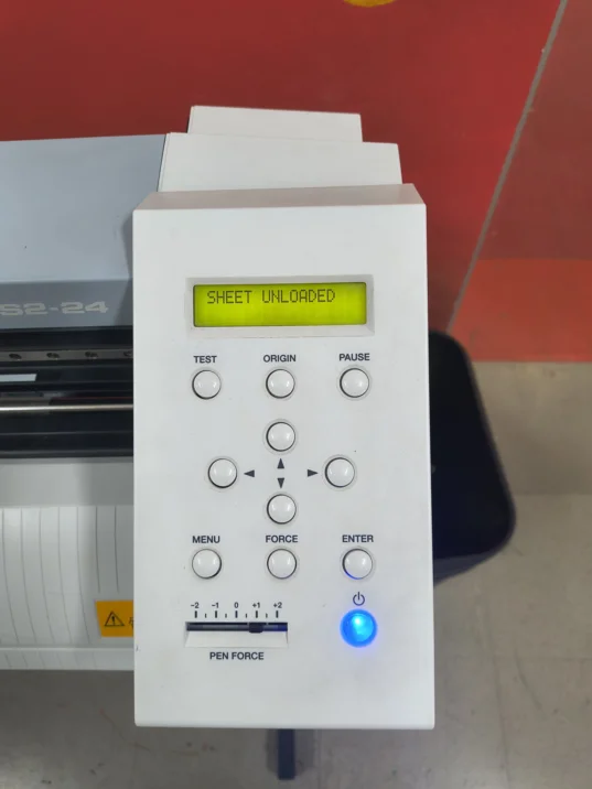
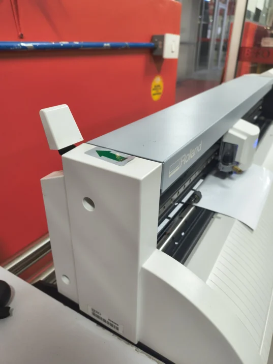
Step 1: Power up the main cutting machine hardware and engage the rear loading levers to feed the raw single sheet material or bulk vinyl adhesive roll stock past the primary tracking sensors.
Step 2: Align the edges along the reference guidelines and clamp down the pinch roller wheels over the material substrate to fully lock the tracking sheet alignment in place.
Step 3: Running the vector.
Step 4: Carefully retrieve your output sheet, weed away the negative scrap areas using fine tweezers, apply transfer tape over the remaining mask shapes, and rub it firmly onto the clean surfaces of your target objects.
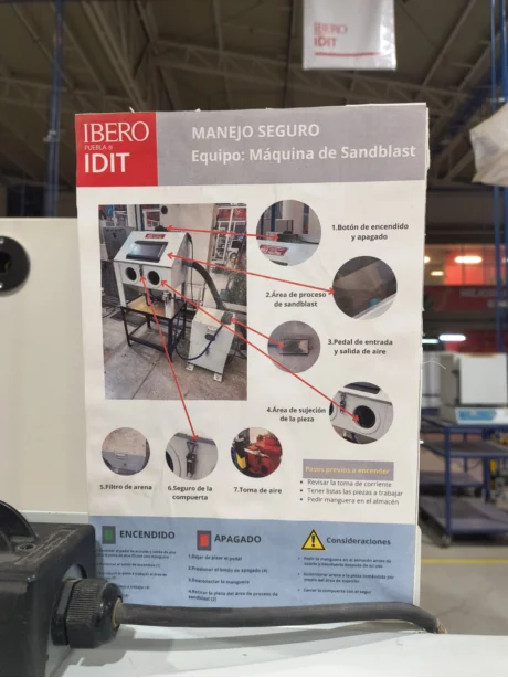
Abrasive Blasting Operation
Safely handling pressurized blasting equipment requires specific sequencing rules to avoid exposure risks and preserve material finishes.
Step 1: Clean down your physical workstation workspace thoroughly and wear your personal protection equipment (PPE), including face ventilation dust shields and thick safety gear.
Step 2: Connect the pneumatic foot control pedal to the heavy-duty air regulator line to feed pressure into the mixing blast valve assembly.
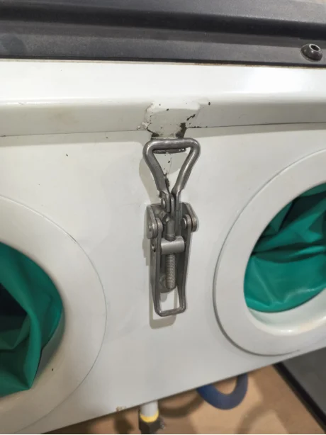
Step 3: Unlatch the heavy view-door assembly window, position your masked object and lock the latch handles back down securely.
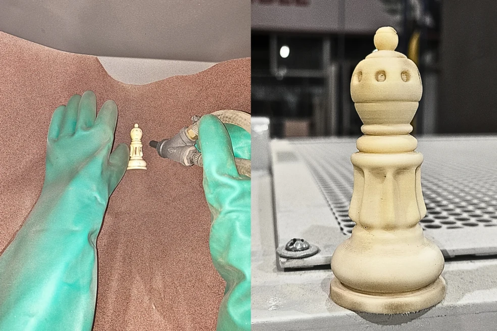
Step 4: Turn on the internal chamber work light and vacuum extraction blower fans. Slip your hands inside the thick protective gloves, grip the blasting nozzle, and depress the pedal to spray abrasive media over the unmasked areas.
Step 5: Remove your components from the chamber cabinet, place them on the bench, and peel away the remaining vinyl mask stencils to reveal the sharp, frosted graphic edge contrasts beneath.
Step 6: Depressurize the system line entirely, isolate the primary electrical master switch, and disconnect the main supply air lines to store the equipment safely.
Abrasive Output Comparison
An overview of the resulting material conversions achieved on both the bottle surface and 3d print.
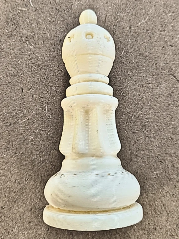
Raw 3D Print Control: In this photo the 3D print has visible layer lines and a glossy surface.
Sandblasted 3D Print: I post processed the 3D print for about 2-5 minutes and it helped smooth some layer lines and create a matte finish.
2. Electroplating Process
What is it?
Electroplating is an electrochemical deposition process where metal ions in a chemical solution are reduced via an electrical current to form a thin, coherent metal coating over a conductive substrate. For non-conductive parts (like 3D prints), a specialized conductive coating must be applied before submersion to close the electrical circuit.
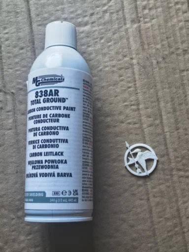
For this experiment, I downloaded and 3D printed a mockingjay model from Thingiverse. To make the 3D print surface electrically active, I applied a layer of conductive paint. Then formulated the electrolyte solution by measuring copper sulfate and dissolving it into distilled water until it achieved full saturation. Before applying the electrical current, I connected the conductive 3D printed piece to the negative terminal (Cathode) and a pure copper plate to the positive terminal (Anode). Once everything was secure, I applied voltage and current for approximately one hour, and some copper ions began bonding onto the print.
Electroplating Process Step by Step
Detailed workflow for preparing, calculating, and executing the electrodeposition process on a 3D printed model.
Step 1: I 3D printed a 4cm mockingjay model I found on Thingiverse with PLA.
Step 2: Then I applied three uniform coats of conductive paint. In this case, I used the MG Chemicals 838AR Total Ground carbon conductive paint. As indicated on its data sheet, I waited a 3 minute flash-off period between layers to ensure proper solvent evaporation and prevent the acrylic lacquer from softening the PLA fine details.
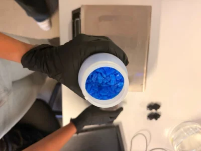
Step 3: Calculate and measure the required amount of dry copper sulfate crystals using a precision digital scale to achieve the correct concentration target for our electrodeposition tank.
The standard formulation requires a ratio of 200 grams of Copper Sulfate Pentahydrate (CuSO₄·5H₂O) per 1 Liter of distilled water to ensure an optimal concentration of copper ions.
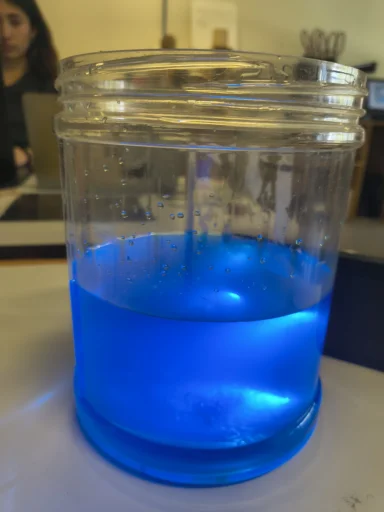
Step 4: Mix the measured copper sulfate crystals thoroughly into a beaker of pure distilled water. Stir continuously until the crystalline solids are completely dissolved, yielding a clear, bright blue electrolyte fluid. For this exercise I used 1L of distilled water and dissolved exactly 200 grams of CuSO₄.
Step 5: Submerge the components into the bath and power on the system. Wire the copper anode sheet to the positive lead (+) and the carbon-painted model to the negative lead (-). It takes time for the ionic transfer process to take place inside the solution.
Why this wiring matters?
Negative Lead (-) / Cathode (The Model): Charging the PLA model negatively attracts the positive copper ions floating in the solution, forcing them to bond and turn into solid metal on the painted surface.
Positive Lead (+) / Anode (The Copper Sheet): The power supply strips electrons from the copper plate, dissolving it into the bath as new copper ions. This continuously replenishes the electrolyte solution.
Warning: Reversing the polarity would dissolve any copper on the model and strip the conductive paint.
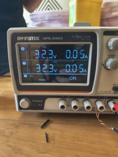
Step 6: Configure and document the finalized voltage, current, and time variables on the laboratory bench power supply unit. Maintain tight regulation to avoid scorching or burning the delicate deposited layer.
Plating Current & Parameter Matrix
Electroplating is governed by Faraday's Laws of Electrolysis, which state that the mass of altered material is directly proportional to the electric current. To achieve a smooth, bright copper finish without burning the piece, we must balance the Total Surface Area (A) with a safe Current Density (J) limit before powering the system.
Mathematical Target: I = A × J
Estimated Area (A): ~50.26 cm² (0.5026 dm²). Calculated treating the 4 cm model as a bounding sphere (4 × π × r²) to establish an upper geometric framework.
Target Current Density (J): 0.015 A/cm². Standard conservative limit recommended for carbon-coated substrates to prevent localized hotspots.
Theoretical Target525 mA (0.525 A)
Real Lab Execution5 mA (32.3V)
Ohmic Analysis: The massive divergence between theory and reality is governed by Ohm's Law (I = V/R). According to the product's Technical Data Sheet (TDS), the MG Chemicals 838AR carbon paint has a high surface resistance of 100 Ω/sq at a 50 μm thickness. This initial resistance bottleneck forced the power supply to scale up to 32.3V just to drive a minimal functional current of 5 mA through the piece.
CRITICAL WARNING: Operating an aqueous cell at 32.3V requires extreme caution. Such high voltage can induce localized overheating, accelerate water electrolysis (generating highly flammable hydrogen and oxygen gases), and risk short-circuits. Constant monitoring and tight ventilation are mandatory.
Analysis of Plating Failures & Boundary Parameters
An examination of deposition irregularities, electrical constraints, and the analytical logic used to solve operational bottleneck problems.
Close-up Analysis: The plating was only partially successful. Copper deposition occurred predominantly on the localized boundaries where the cathode wire made direct contact and at the fluid line interface, leaving the deeper surfaces bare.
Error 1 (Substrate Resistance Bottleneck): The primary failure mode was governed by the electrical constraints of our conductive layer. Unlike silver or copper-filled coatings, the carbon-pigmented acrylic lacquer introduces a substantial initial resistance across complex organic geometries. This caused an immediate voltage drop away from the contact clip, restricting ionic bonding to the nearest low-resistance paths.
MG Chemicals 838AR Technical Verified Specs:
Property
Value / Specification
Surface Resistance
100 Ω/sq (50 μm)
Volume Resistivity
0.63 Ω·cm
Adhesion Rating (PLA)
5B (Excellent Cross-Hatch)
Full Cure Parameters
24 hours Room Temp
*Optimization Lesson:* For future trials using carbon lacquers, burnishing the completely cured surface with a micro-abrasive cloth or graphite powder can mechanically align the carbon atoms, dropping the initial surface resistance significantly before immersion.
Error 2 (High Voltage vs Low Current Dynamic): When powering the system, the cell required an unexpected 32.3V to push a minor current of 0.005A (5 mA). In standard electroplating, high voltages trigger water electrolysis instead of metallic deposition, creating hydrogen gas bubbles that block copper ions from reaching the cathode.
The Electrolysis Phenomenon
When the cell resistance is too high, scaling up the power supply voltage forces the system past the safe decomposition potential of water. This causes the fluid to split into Hydrogen gas (at the model) and Oxygen gas (at the anode plate), creating an insulation blanket of microscopic bubbles that hinders uniform copper crystallization.
Electrochemical Analysis: This experiment perfectly demonstrates the interaction between solution chemistry and Ohm's Law (Voltage = Current × Resistance). The total system resistance was heavily dominated by the carbon track rather than the fluid electrolyte bath.
The Mathematical Diagnosis
Total System Resistance (R) = V / I = 32.3V / 0.005A = 6,460 Ω
Conclusion: A resistance of 6.46 kΩ proves that the electrolyte concentration was safe, but the conductive boundary was acting as an electrical bottleneck. To solve this in future Fab Academy cycles, the model requires multiple overlapping coats of paint, optimized contact points distributed around the mesh, and a continuous low-voltage ramp-up strategy.
Future Improvements for Electroplating
This experiment was useful because it showed the limits of the process, especially how much the conductive coating and electrical contact affect the final copper deposition. If I repeated the exercise, I would redesign both the preparation and the setup to reduce resistance and make the coating more uniform.
Test a DIY Conductive Paint Method
For a future test, I would try the conductive paint method shown in this video. The author prepares a DIY graphite-based paint using acetone, a binder, and 99% pure graphite powder, then applies at least five airbrushed coats while polishing between layers to improve conductivity. I also recommend the HEN3DRIK - Electroplating 3D Prints channel because it explains the process step by step, including material preparation, current calculation, and safety.
Key Notes from the Video
The surface must be very clean before painting because electroplating amplifies imperfections. For the bath setup, the video uses bright acid copper electrolyte, copper anodes inside coffee filters, and a constant-current power supply. The current is calculated based on surface area, using around 1-2 A per dm². The author also emphasizes ventilation, gloves, eye protection, a respirator for paint fumes, and proper chemical waste disposal.
Improve Electrical Contact
The copper deposited mostly near the clip, so a better setup would use multiple contact points or a thin conductive wire wrapped around less visible areas of the model.
Control Voltage and Current
Instead of forcing a high voltage to get a small current, I would start with a lower voltage and increase it gradually while monitoring current and bubbles.
Redesign the Test Piece
For a cleaner comparison, I would test a simpler rounded geometry first and then repeat the process on a more detailed piece like the mockingjay.
2. Thermoforming Process
What is it?
Thermoforming is a manufacturing technique where a plastic sheet is heated to a pliable forming temperature, stretched over or into a single-surface mold, and held against the mold by applying vacuum pressure. Once cooled, the plastic retains the details of the master mold shape and can be trimmed for final assembly.
For this process, I experimented with creating custom molds using 3D printing parameters to test the precision limits and geometrical constraints of vacuum forming over rigid plastics. I used a polystyrene sheet cut precisely to match the machine's dimensions and evaluated how different shape factors ranging from strict geometric configurations to low-profile relief silhouettes behave during the critical cooling and demolding release phases. To understand the process, materials, equipment, and mold considerations in more detail, I also consulted the Formlabs thermoforming guide.
Thermoforming Process Step by Step
Creating solid master tooling geometries capable of withstanding both the temperature shifts and the intense directional suction forces of the vacuum cell. Securing raw material stocks, dialing thermal boundaries, and coordinating mechanical controls to guarantee optimal plastic deformation.
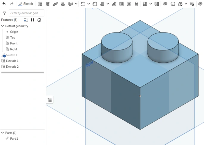
Step 1: I 3D modeled a figure similar to a LEGO brick on Onshape, I decided use this shape to analyze interlocking tolerances and vertical wall restrictions.
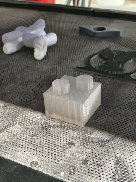
Step 2: The master piece was 3D printed with translucent PLA filament, keeping solid perimeter structures to prevent shell collapse under thermal stress.
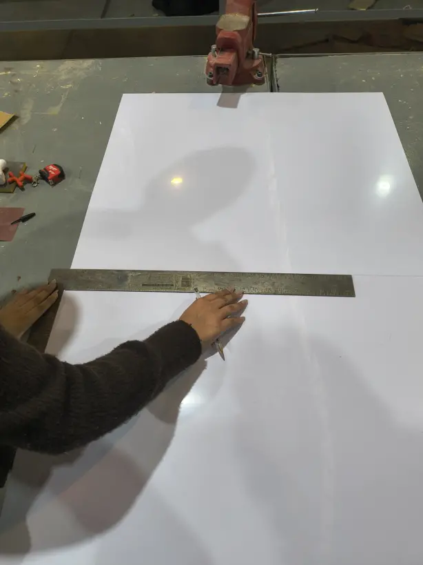
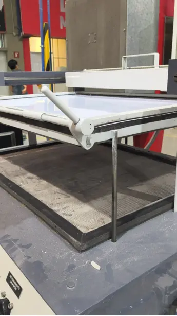
Step 3: Measure the raw styrene material sheet stock and cut it directly down to 54 cm x 75 cm, which matches the exact dimensions of the thermoformer clamp bed framing workspace.
Step 4: Position the prepared plastic sheet directly onto the structural perimeter frame and clamp it down safely over the bed to seal the pressure zone.
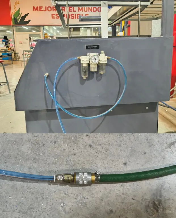
Step 5: Connect the pneumatic high-pressure air line manifold to the machine input valves and elevate the main workspace bed frame upward.
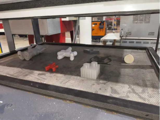
Step 6: Arrange and position the target 3D printed master molds over the thermoformer lower tooling baseplate array with adequate separating clearances.
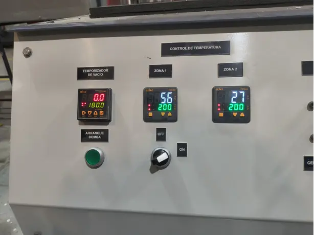
Step 7: Turn on the primary temperature controller instrumentation and ramp the thermal setting window up to 200°C to heat the sheet to its soft transition point.
Step 8: Once the sheet stretches into its pliable state, engage the pump startup button (arranque de bomba), drive the piston assembly downward, and actuate the main pneumatic air valve to form the part.
Results & Geometrical Constraint Analysis
An evaluation of dimensional edge accuracy and design flaws discovered during the mechanical separation of parts.
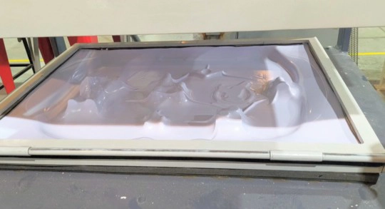
Resulting Plate: Overview of the complete molded styrene plate right after vacuum draw down and cooling.
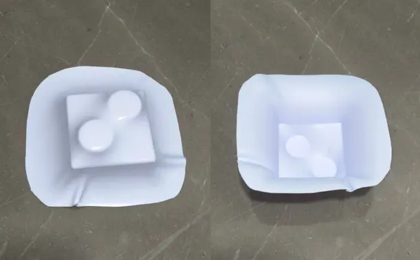
Cube Close-up (Draft Angle Defect): Detailed analysis of the square block profile. This part failed to extract safely because zero draft angles were integrated into the vertical design paths, causing the cooling plastic to permanently lock around the 90° straight walls.
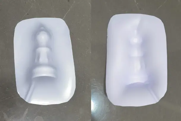
Chess Piece Close-up: This component had better results. The plastic sheet conformed smoothly around the organic surface transitions and structural curves, providing clean definition without locking mechanical walls. However, there is a lot of room for improvement.
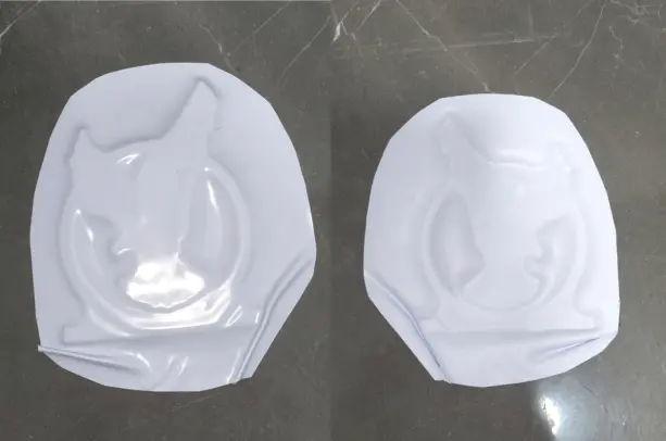
Eagle Model Relief Close-up: The shallow eagle silhouette generated a clean, subtle relief layout. This confirms that minimal depth maps reduce localized material thinning and maximize structural definition across planar surfaces.
Future Improvements for Thermoforming
The thermoforming test showed that the process depends not only on heating and vacuum pressure, but also on the geometry of the mold. The LEGO-like piece was useful because it made the limits visible: vertical walls, sharp corners, and low clearance can trap the plastic and make demolding difficult.
In theory, these design changes should help the thermoformed piece come out better by improving suction, detail definition, material flow, and release from the mold.
Add Draft Angles
For the redesigned mold, I added draft angles to the vertical walls. A draft angle of at least 2 degrees is recommended so the formed plastic can release after cooling without locking around the mold.
Raise the Mold Base
I raised the mold by creating a support base with a 10 mm offset and a 5 mm height. This lifted the part from the thermoforming bed and helped the sheet stretch more gradually around the lower edges.
Round Corners and Edges
I softened the sharp corners with fillets between 2 mm and 3 mm. These rounded transitions reduce stress concentration and help the plastic sheet flow more evenly over the mold surface.
Use Vent Holes and Test Geometry
I added small vacuum holes near the junction between the cylinders and also in the center. These were the areas where the previous test didn't define well because the suction was not reaching the details properly. Deciding exactly where to place vent holes can be confusing, so I used the Vaquform vent holes guide to understand how trapped air affects detail definition.



.webp)
.webp)
.webp)
.webp)