5. 3D scanning and printing
This week we learned about the fundamentals of 3D printing and scanning, not only about how they work but also how to design specifically for them by following design rules such as tolerances, wall thickness, overhang angles, support considerations and material limitations.
These technologies are important because they connect the digital and physical worlds in a fast, accessible and precise way. It can help us to tangibilize projects into prototypes or even small scale products.
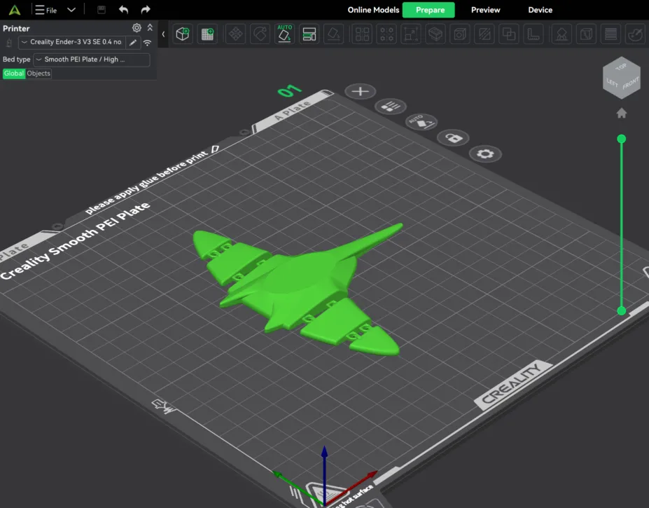
For this assignment I modeled two objects in different programs (Onshape and Maya) and used both filament and resin 3D printing (FDM & MSLA). To know more about 3D Printing check the group asigment.
Manta Ray
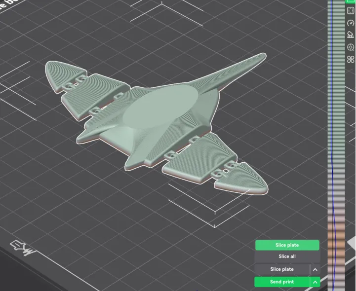
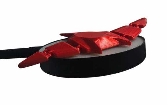
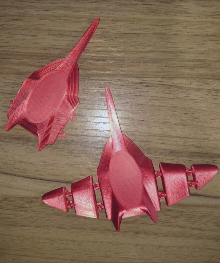
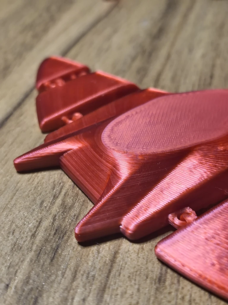
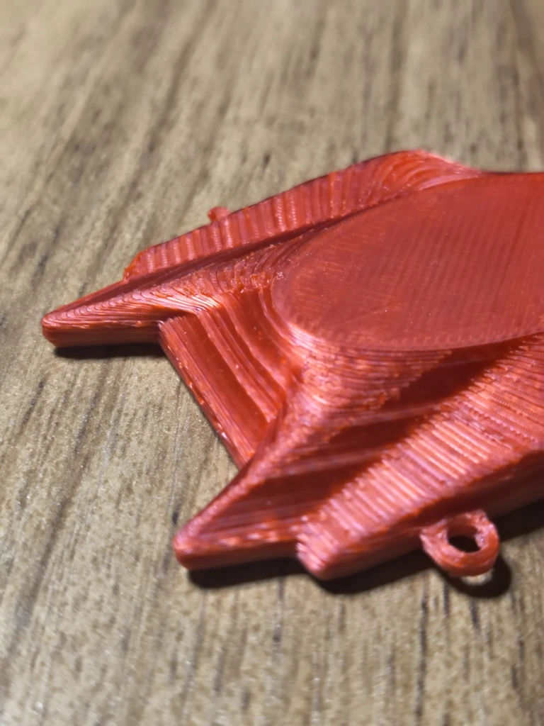
The first object I modeled was a flexible manta ray, for this I used Onshape because it is the CAD I'm more familiar with. The overall tools I used were extrusion, loft and fillets.Modeling in Onshape
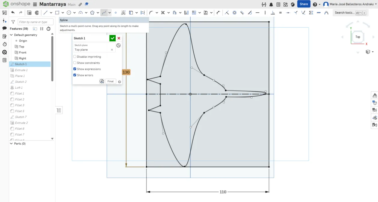
1. Create a new sketch and draw your base siluette. For this drew and dimensioned a rectangle to now the overall dimension I wanted and then I use the tool spline that let use make multi-point curves.
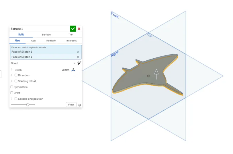
2. Extrude the sketch, in this case I did a 3mm extrusion.
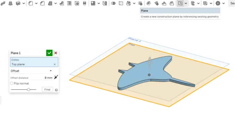
3. Create an offset plane with 8mm distance from the Top plane (we will do a loft so we need some distance)
4. Create a sketch on the plane we created, draw an ellipse that is centered to the manta ray.
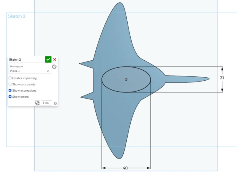
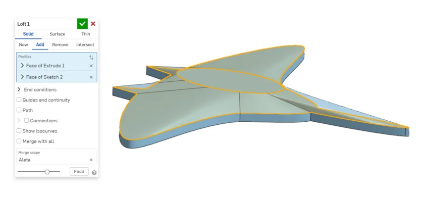
5. Select both the extrusion face of the manta ray and the ellipse we created, and make a loft
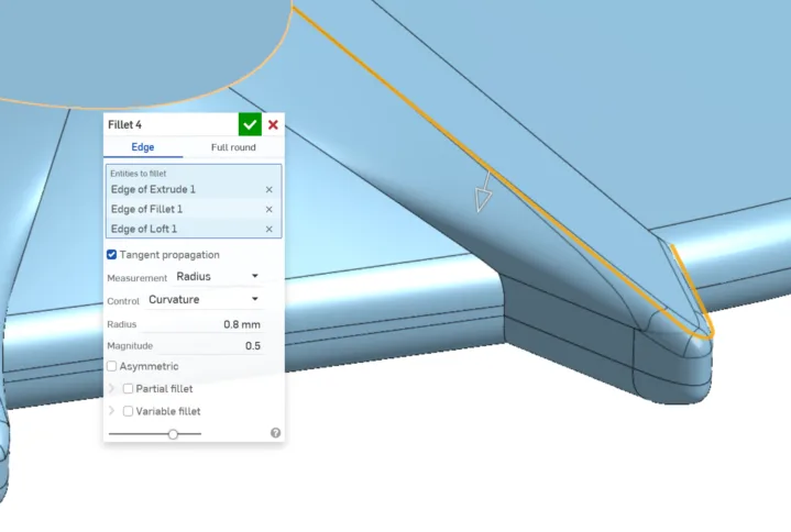
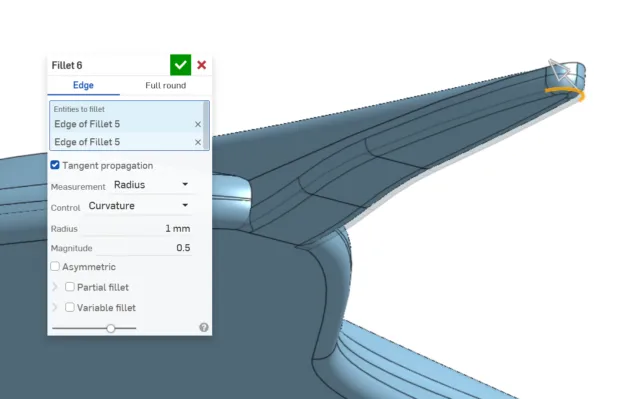
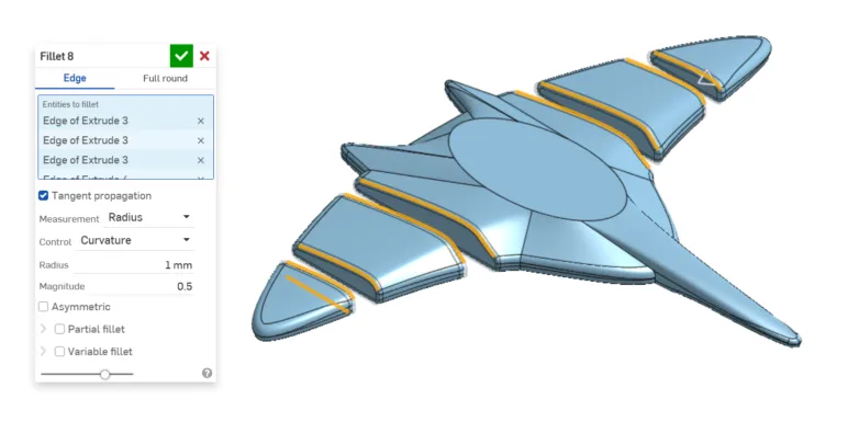
6. Fillet the edges, for this I played with the parameters such as the radius, magnitudes and variable fillets.
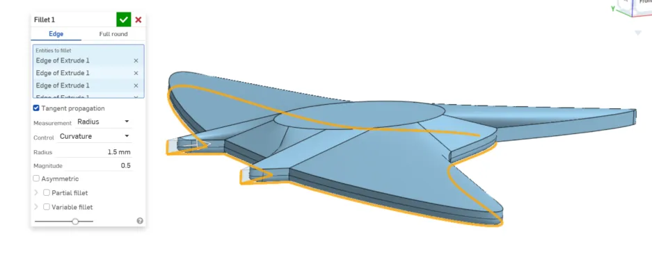
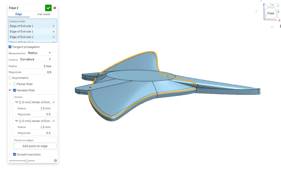
Note: I created different fillet instances because some are edges are not compatible with the same parameters (either the radious is to large of there is self-intersection).
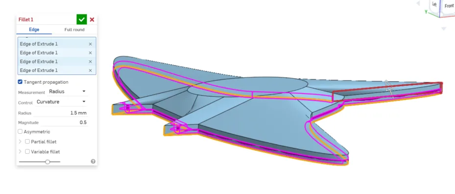
For example in here I used variable fillet because the last two curves didn't accept the 2mm radious but worked just fine with 1.5 mm radious.
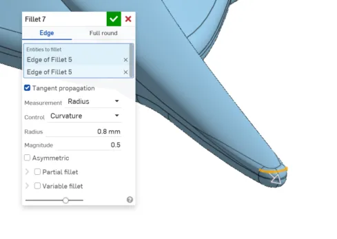
6.1 I also did a small fillet (0.8mm) to the horns.
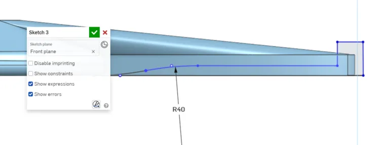
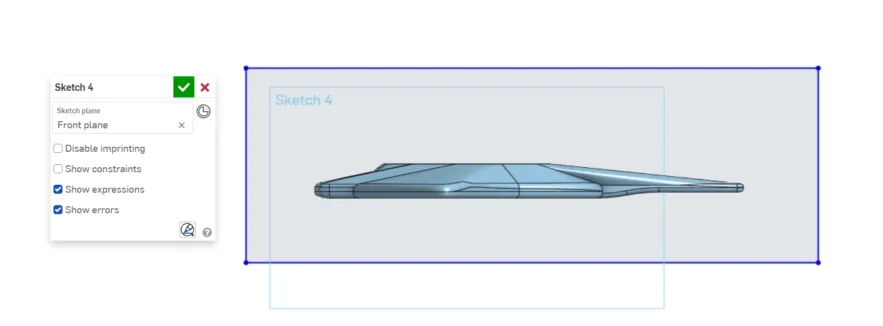
7. Create a sketch on the Front plane and draw the exterior profile of the tail (its not necessary to dimension it that's why the lines are blue).
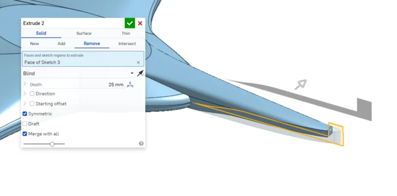
8. Make an extrusion to eliminate that part of the tail, that way it will look more natural.
9. Round the tail with fillets.
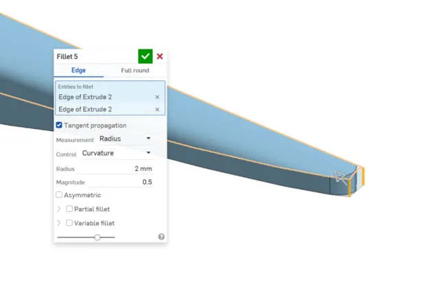
9.1 Change the fillet parameters in case its needed.
9.2 Fillets in general soften the sharp edges, reducing stress, improving the structural performance, printability, and aesthetics.
10. Create a new sketch on Front plane and draw a rectangle that is bigger than the manta ray.
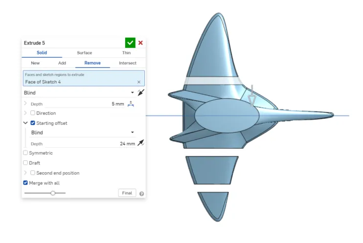
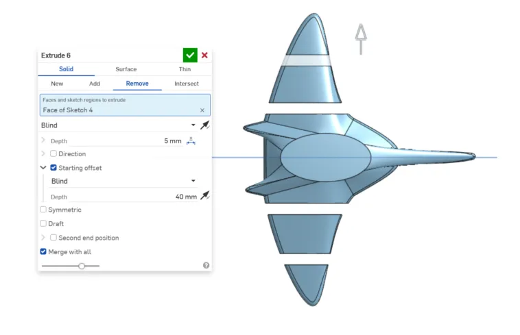
11. With the previous rectangle, make an extrusion to remove material. I used starting offset to control where I wanted the 5mm cut. This will divide our manta ray into different pieces.
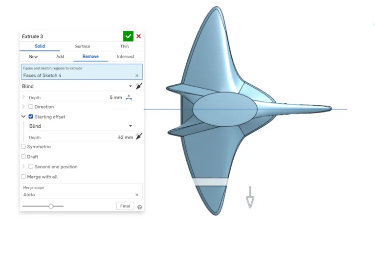
11.1 Repeat the process and change the starting offset distances.
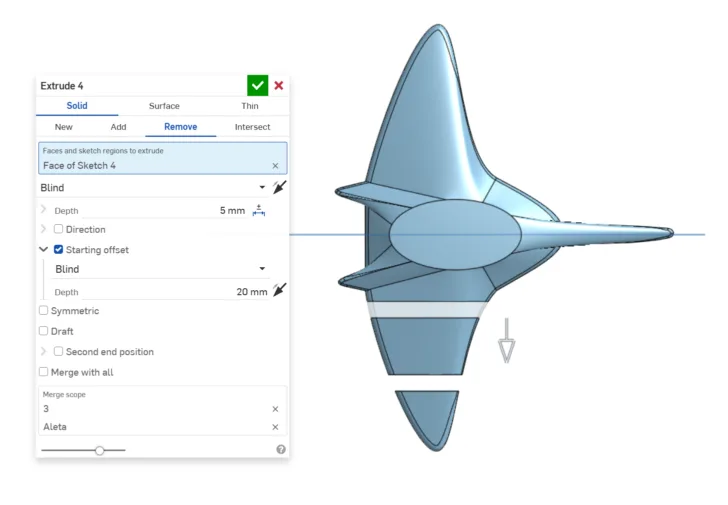
11.2 In total, we are going to make 4 cuts (to have 5 pieces)
Note: You can have the same result by using offset planes and using the tool split.
12. Once you have the pieces, round its corners.
13. Create a sketch on Top plane and draw a slot of 5mm with a concentric circle of 3mm. This will help us create the hinges.
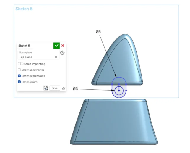
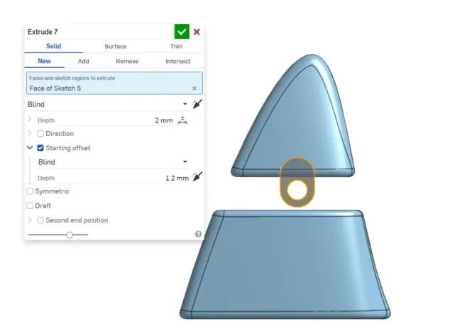
14. Extrude it and center it to your piece.
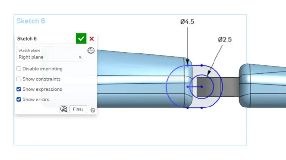
15. Create a sketch on the Right plane, and draw a slot of 4.5 mm and a concentric circle of 2.5mm. This to improve the fit and functionality of the hinge.
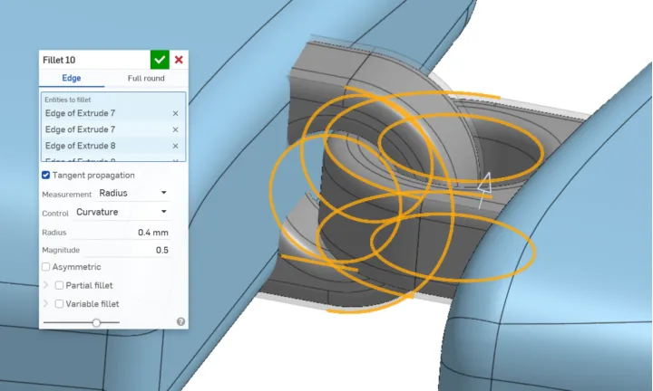
16. Round the corners to improve clearance during rotation and reduce unwanted friction points between parts.
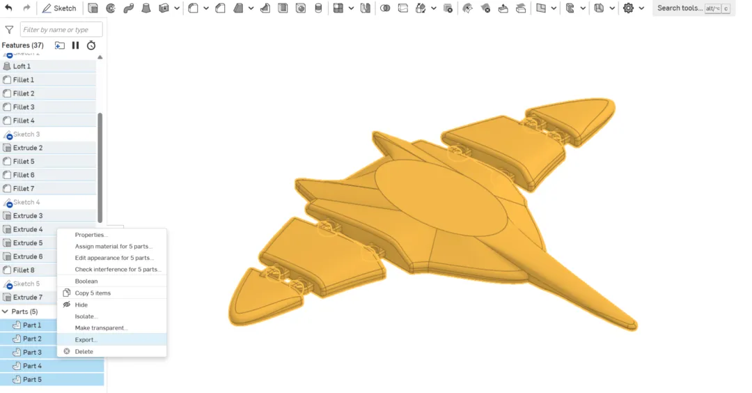
17. Once you have the first hinge use transform and linear patterns to move and duplicate the hinges in the positions you want. After that use the tool boolean to merge the hinges with the parts. This way you will have the 5 final pieces.
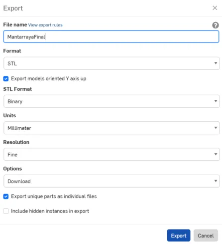
18. Select all the pieces and export them in stl.
18.1 These are the export parameters I used.
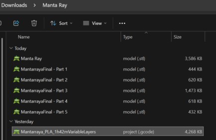
Crab
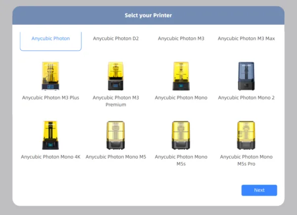
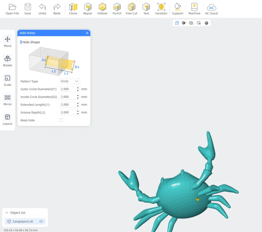
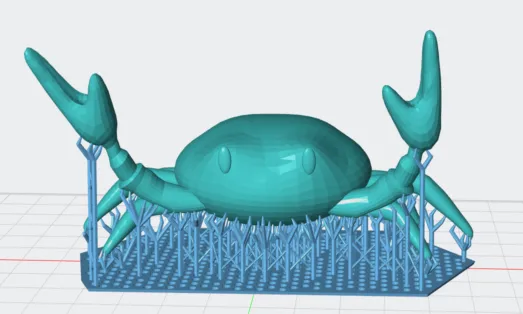
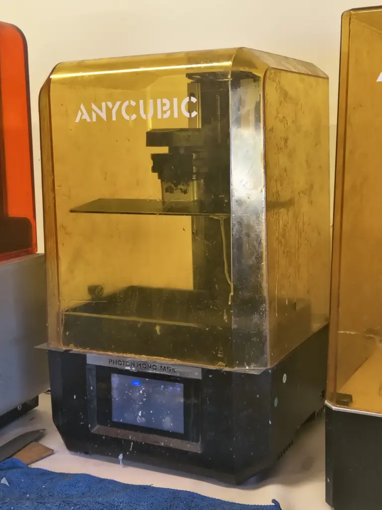
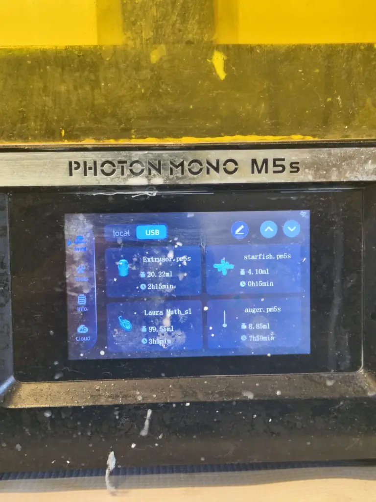
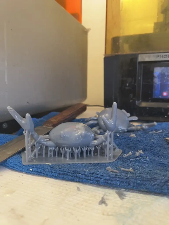
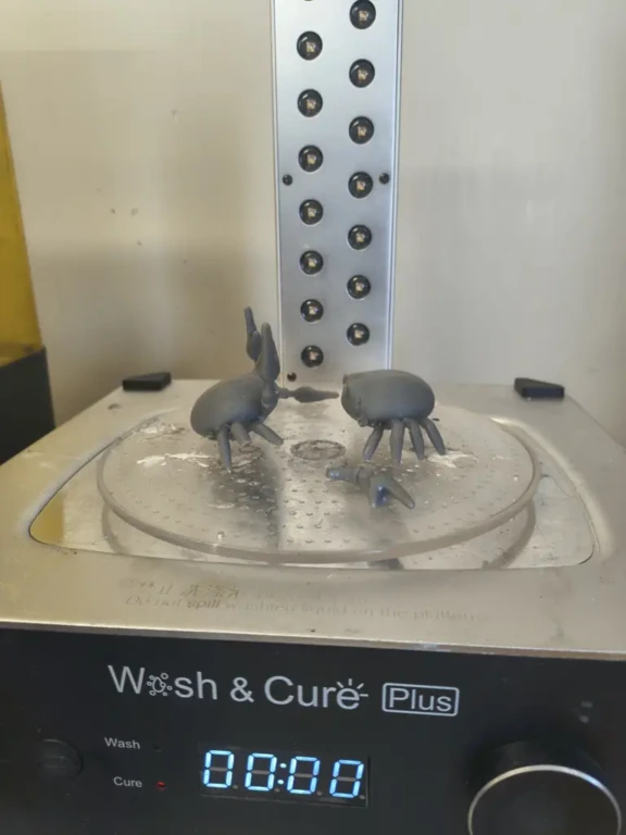
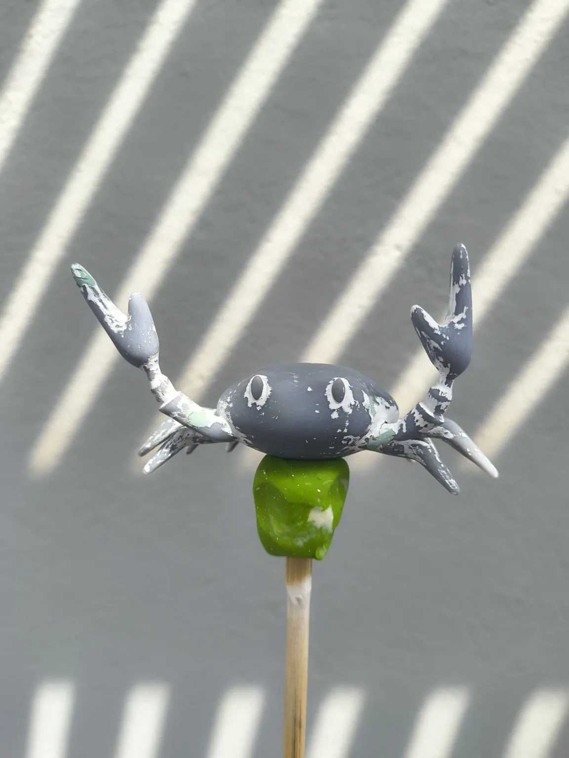
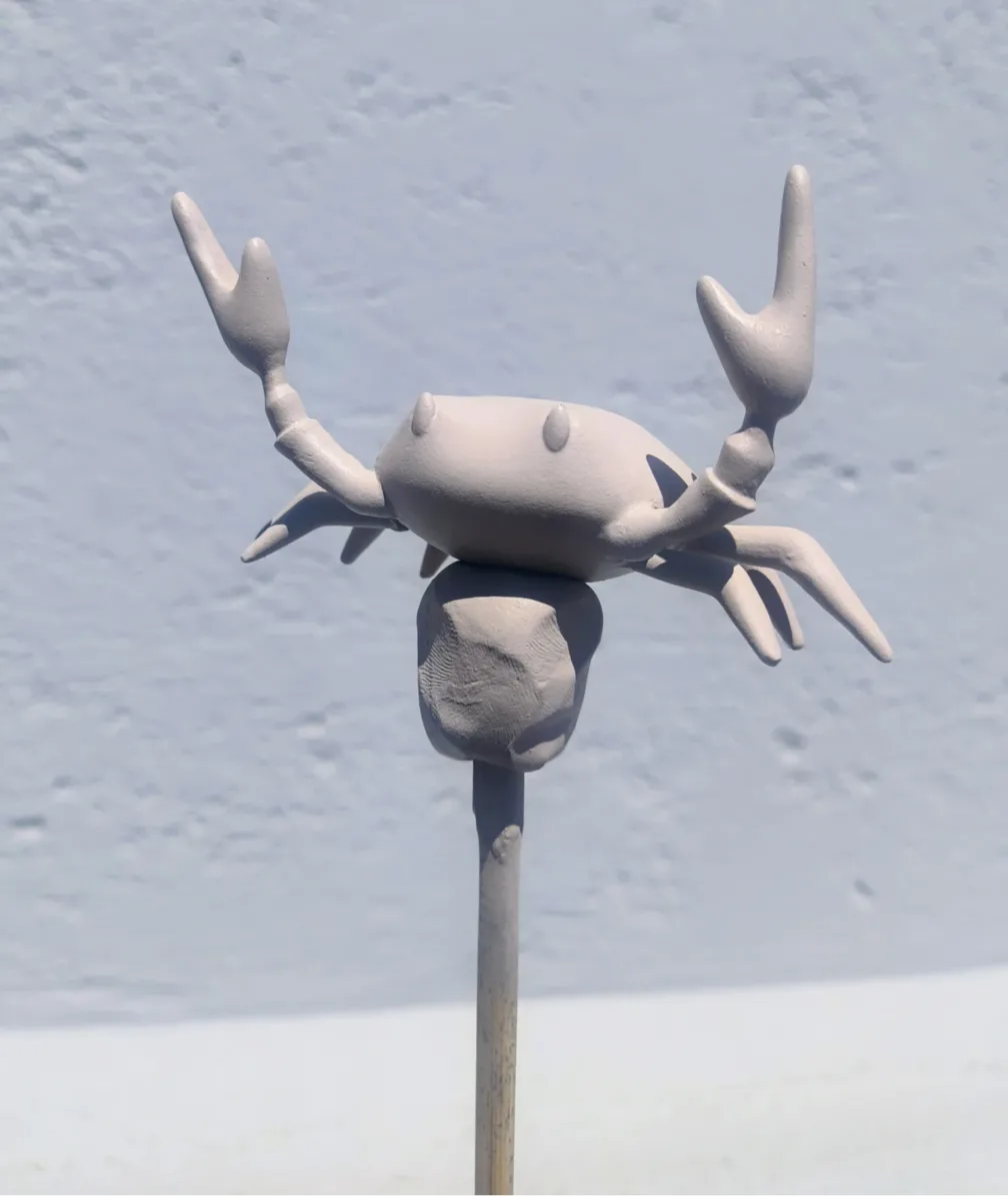
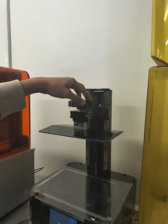
The second object I modeled was a crab, but instead of using a parametric CAD, I used Maya and experimented with resin 3D printing.
Modeling in Maya
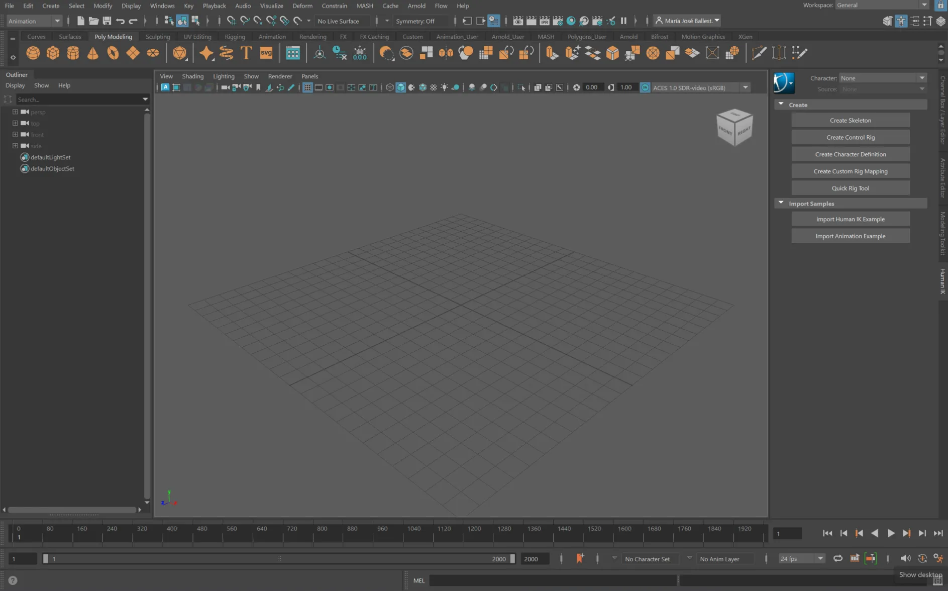
1. Open a new project on Maya.
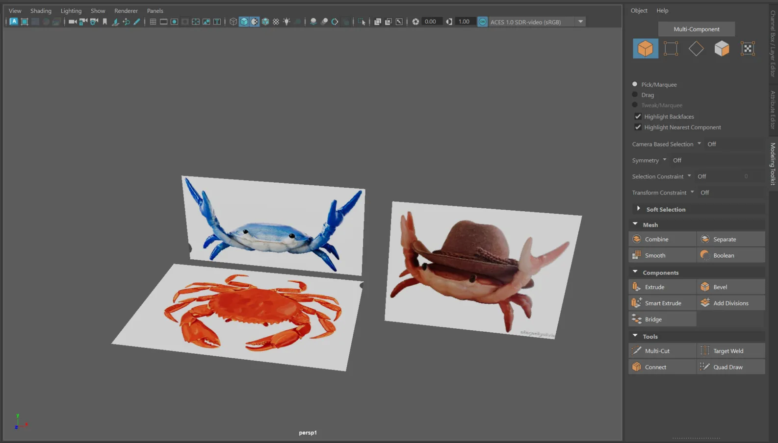
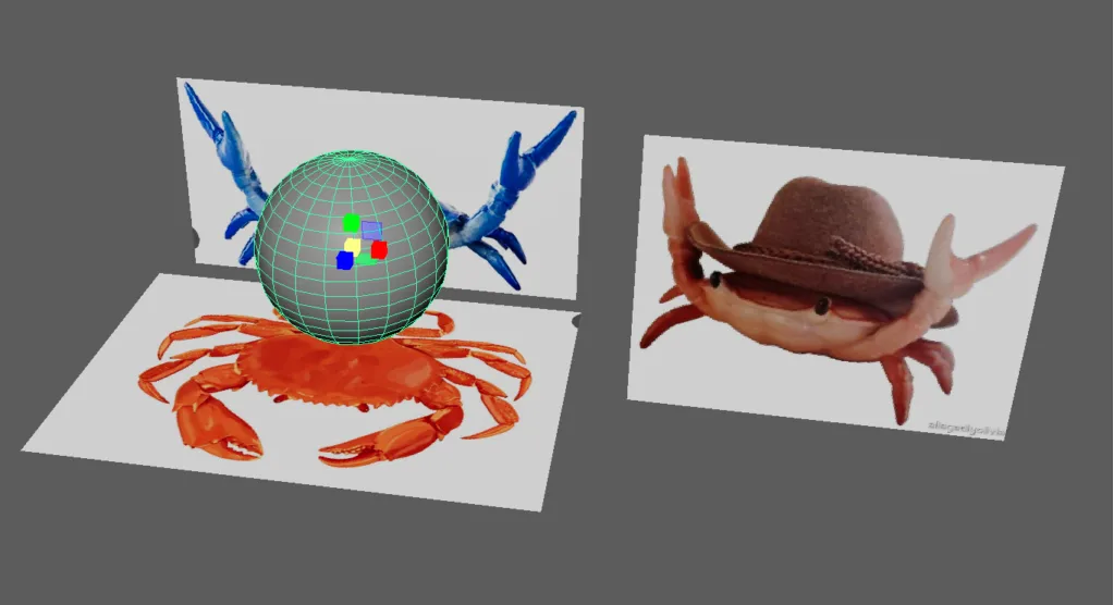
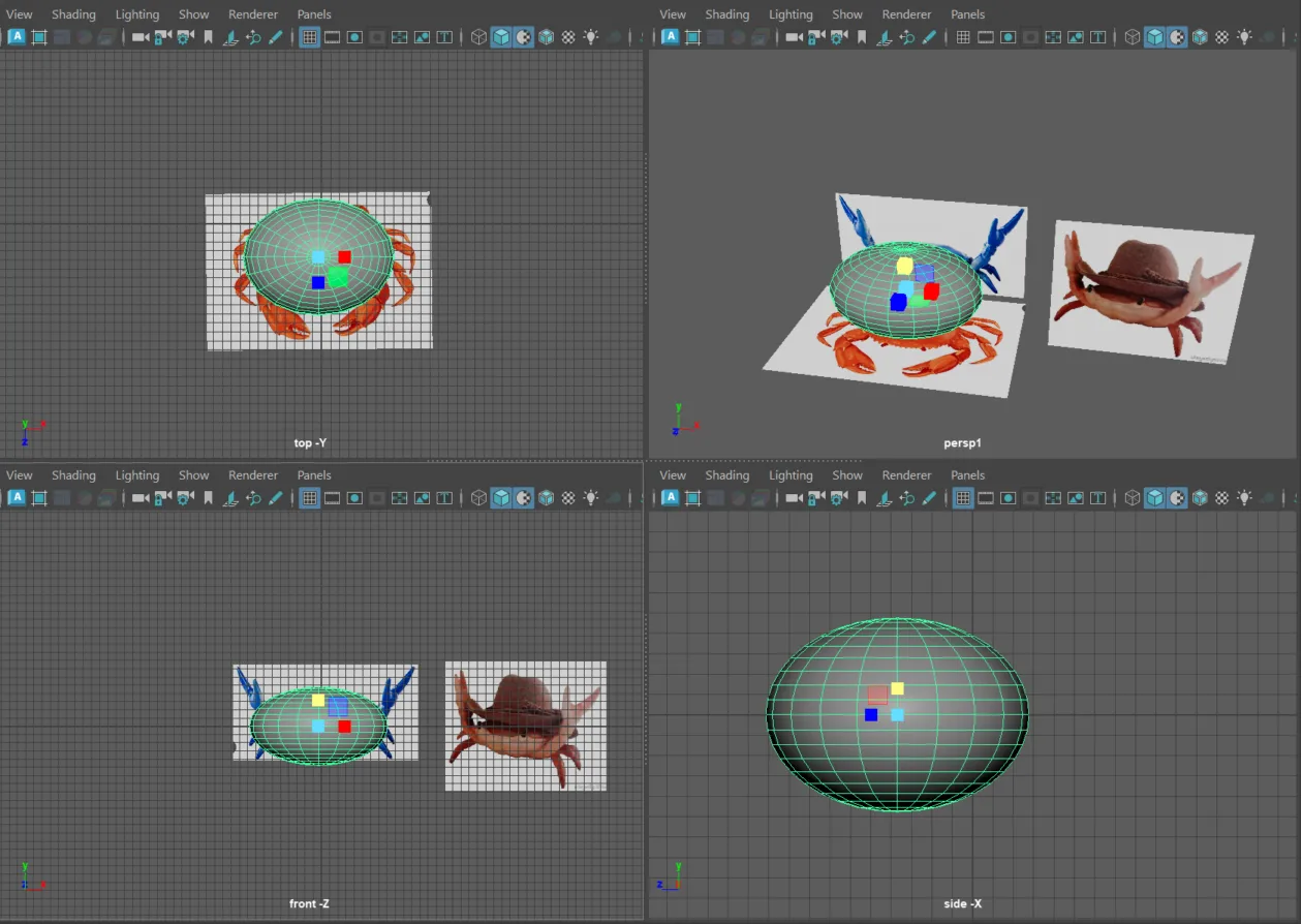
2. Import your reference images (in this case top and fronts views).
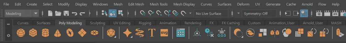
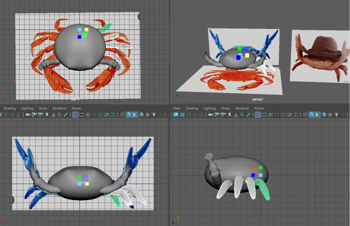
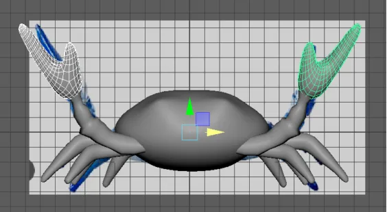
3. Use the poly modeling bar to create a sphere.
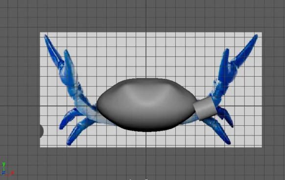
4. Modify the shape of the sphere moving either the Vertex, Edge, or Face components.
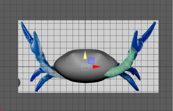
5. Create a cylinder, scale it and rotate it.
6. Modify the shape of the cylinder to make its leg.
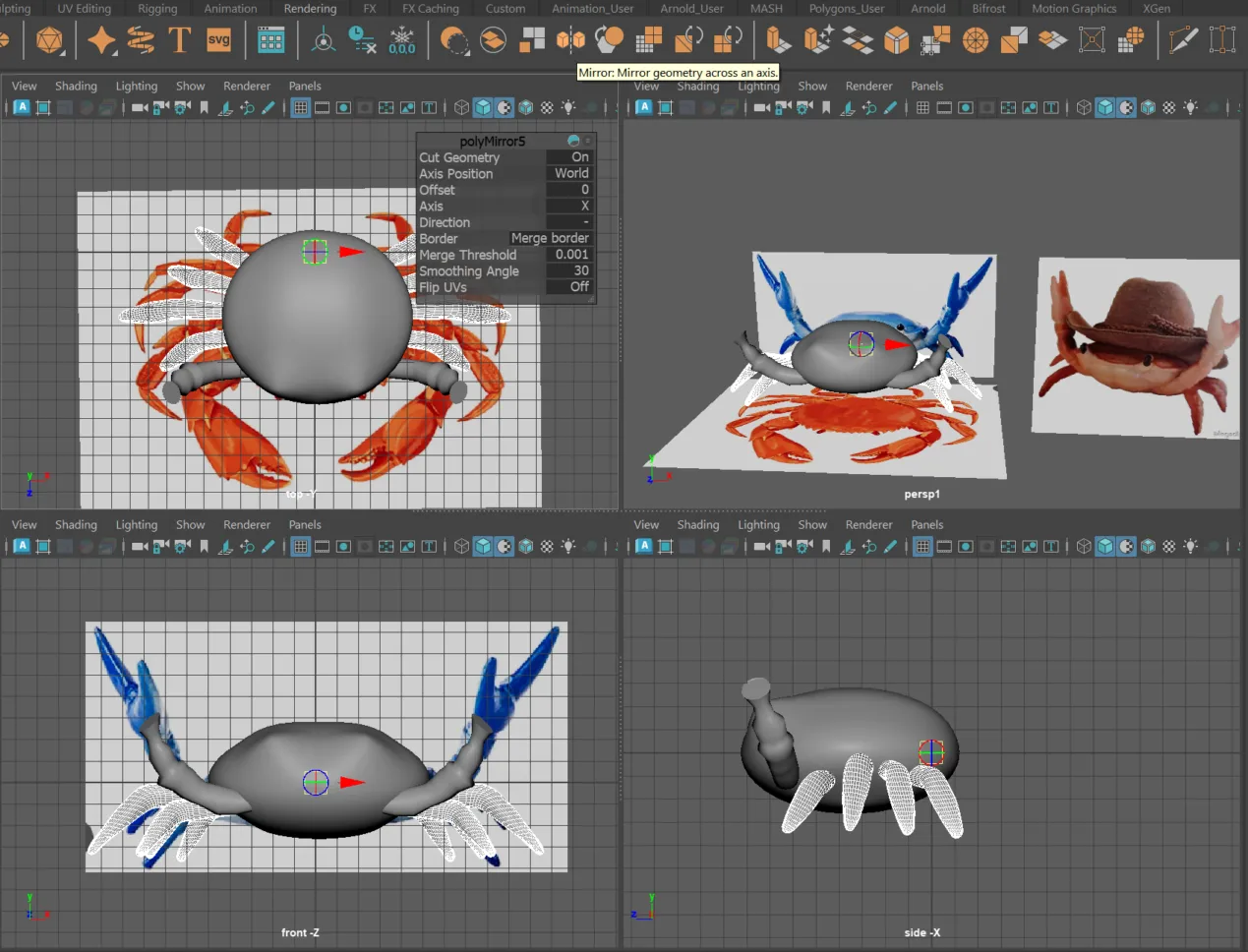
7. Mirror the leg.
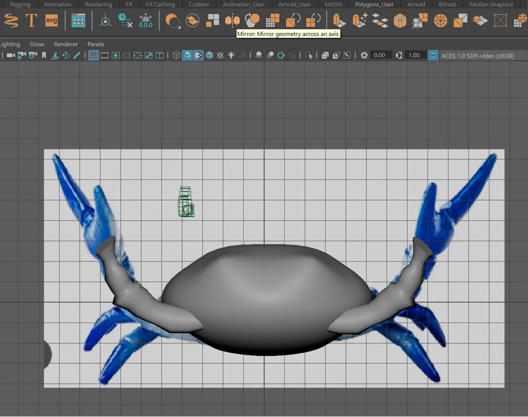
8. Repeat the process but for the other legs.
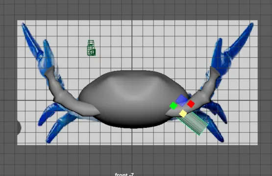
9. Copy the button leg and paste it 3 times.
10. Modify the rest of the legs with scale.
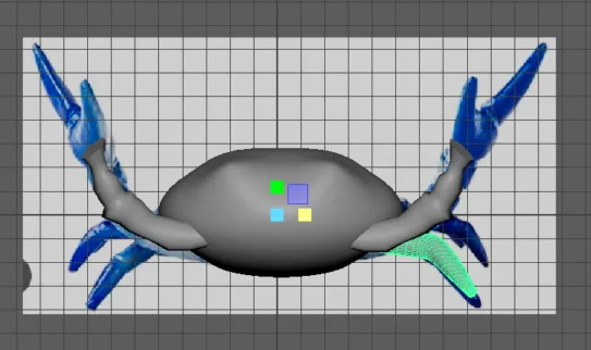
11. Mirror the legs.
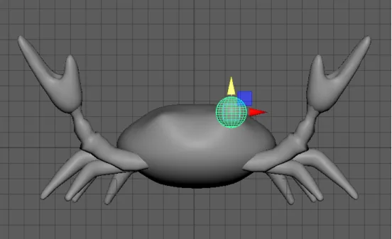
12. Create a sphere to make the claw.
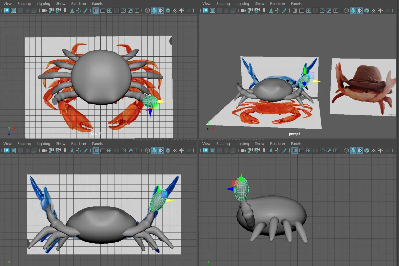
13. Modify its shape. Smooth the shape in case its necessary
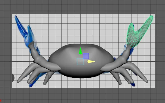
14. Mirror the claw.
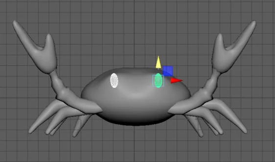
10. Create a sphere to make the eye.
11. Shape it and mirror the eye.
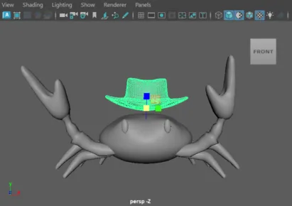
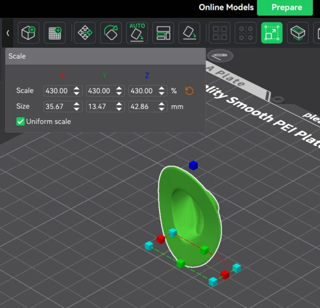
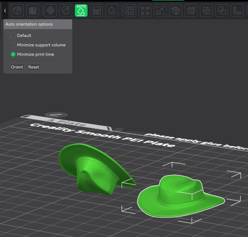
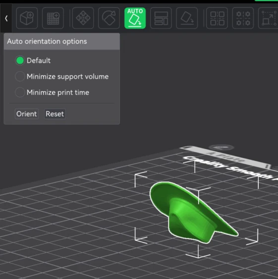
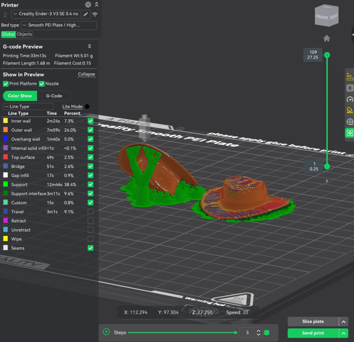
12. For the hat I downloaded one from 3D Cults
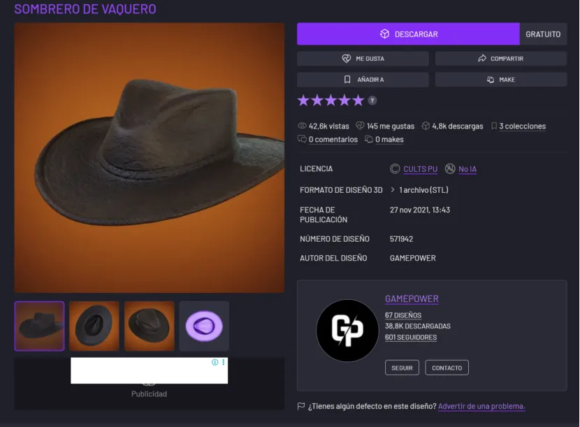
13. Then I edited it to match the crab head size. After that I exported it on STL.
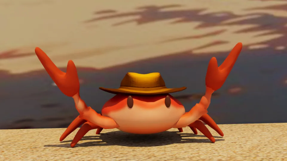
Maya is also known for its lighting, texturing, and simulation tools. That is why I played worth the crab texture paint.
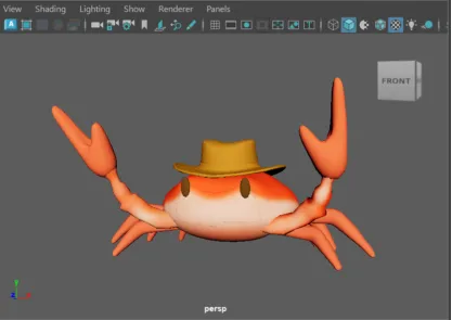
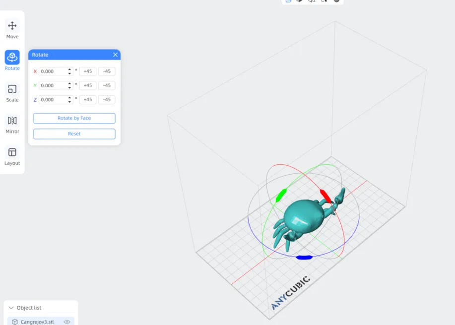
And for the renders I moved the body to make a pose
You can add backgrounds, light and ambience.
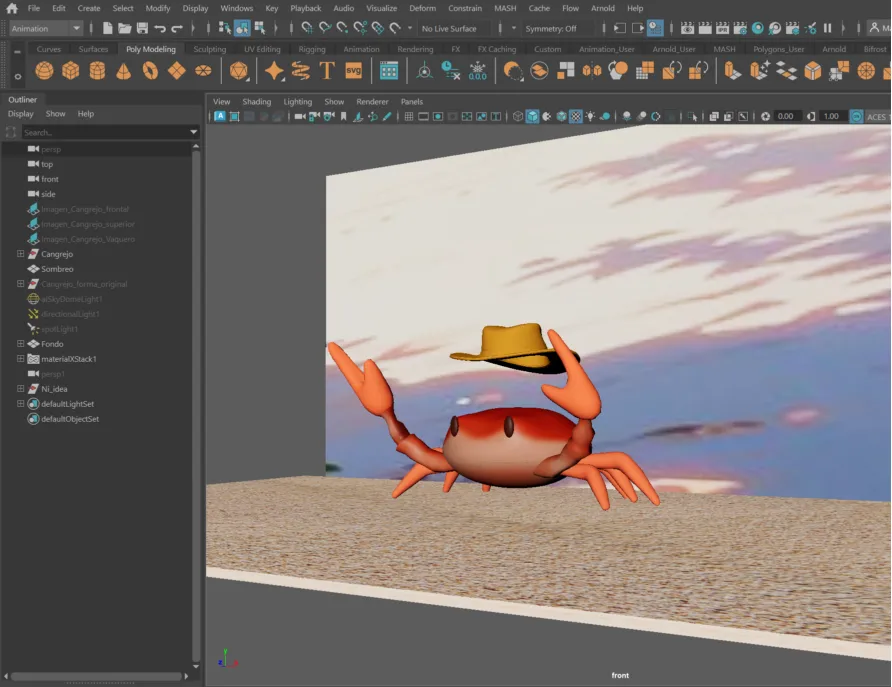
After that I used the Arnold Rendered in Maya.
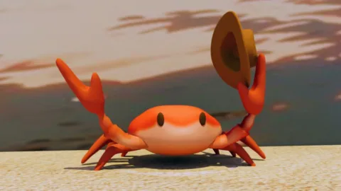
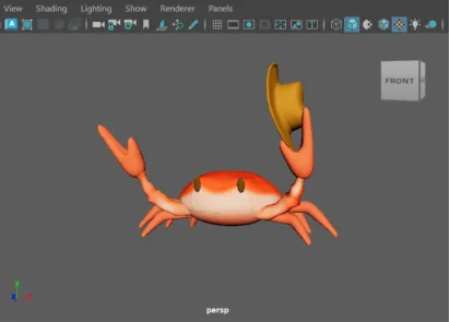
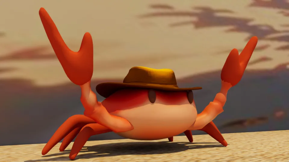
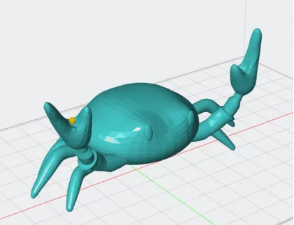
You can play with poses.
Or with camera positions.

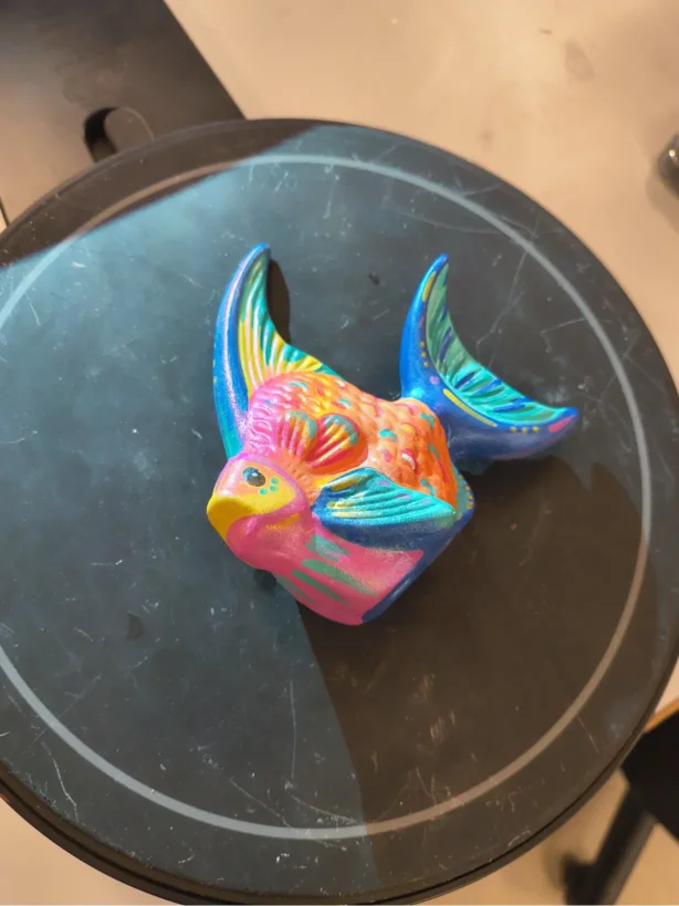
Fish
Lastly I scanned a ceramic fish with the EinScan-SE scanner.Scanning with EXScan Software for the EinScan-SE scanner.
1. Downlaoad and open the EXScan Software.
2. Select new work.
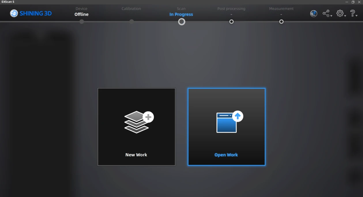
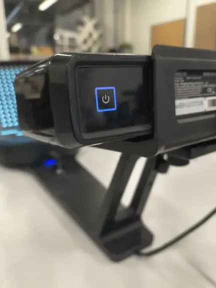
2.1. To be able to create a new work, the scanner must be on and connected via USB to your computer.
3. Then you will need to calibrate the scanner.
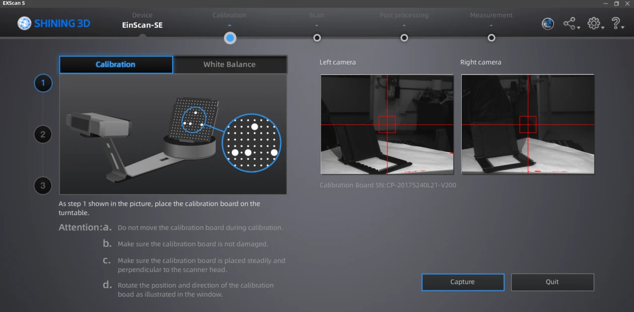
3.1 The first calibration consists of 3 steps. In each step we need to change the board position to how the programs indicates.
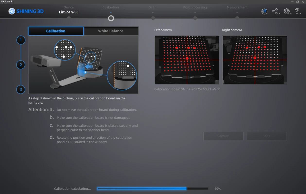
Here is how the calibration works while rotating the board
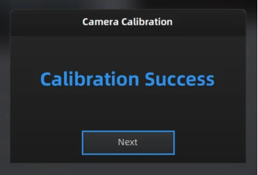
After the calibration is done a message will appear and follow to the white balance calibration.
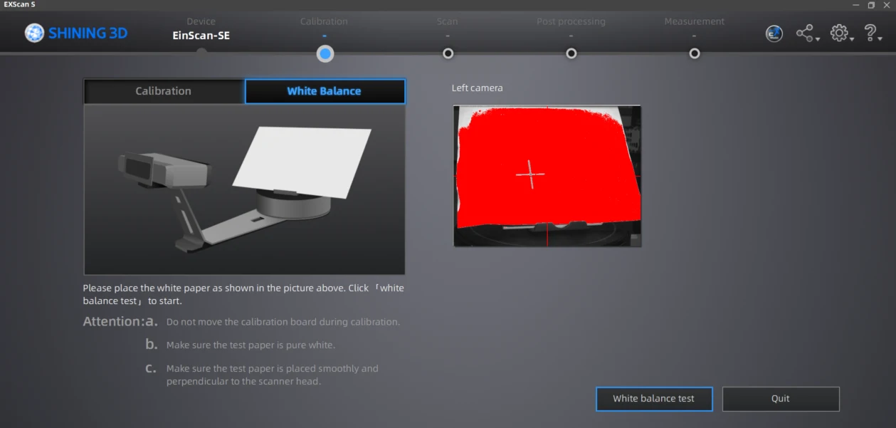
4. To do the white balance you to add a white paper to the board.
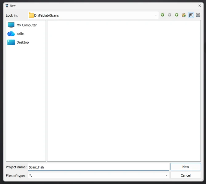
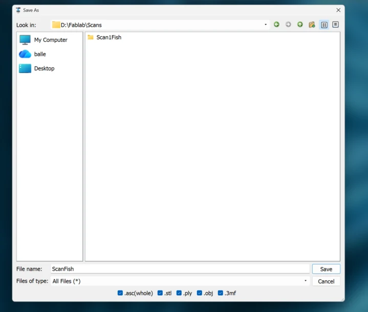
5. After calibration is done, the program will ask you to name and save your new work.
6. Then select if you want a texture or non-texture scan.
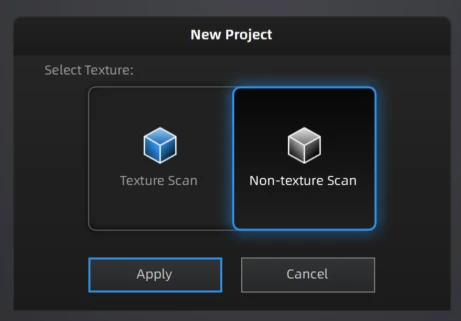
The first one saves the colors and details of the piece while the second one records only the 3D shape. For this exercise I selected the Non-Textured Scan.
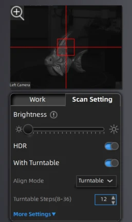
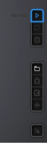
8. After that we can edit the scan settings. I uses low brightness, enabled HDR and Turntable with 12 steps. Then I started the scanning.
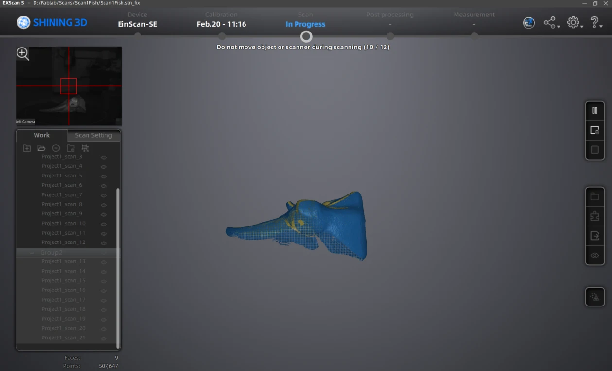
9. Here is an example of how it scans using white light patterns.
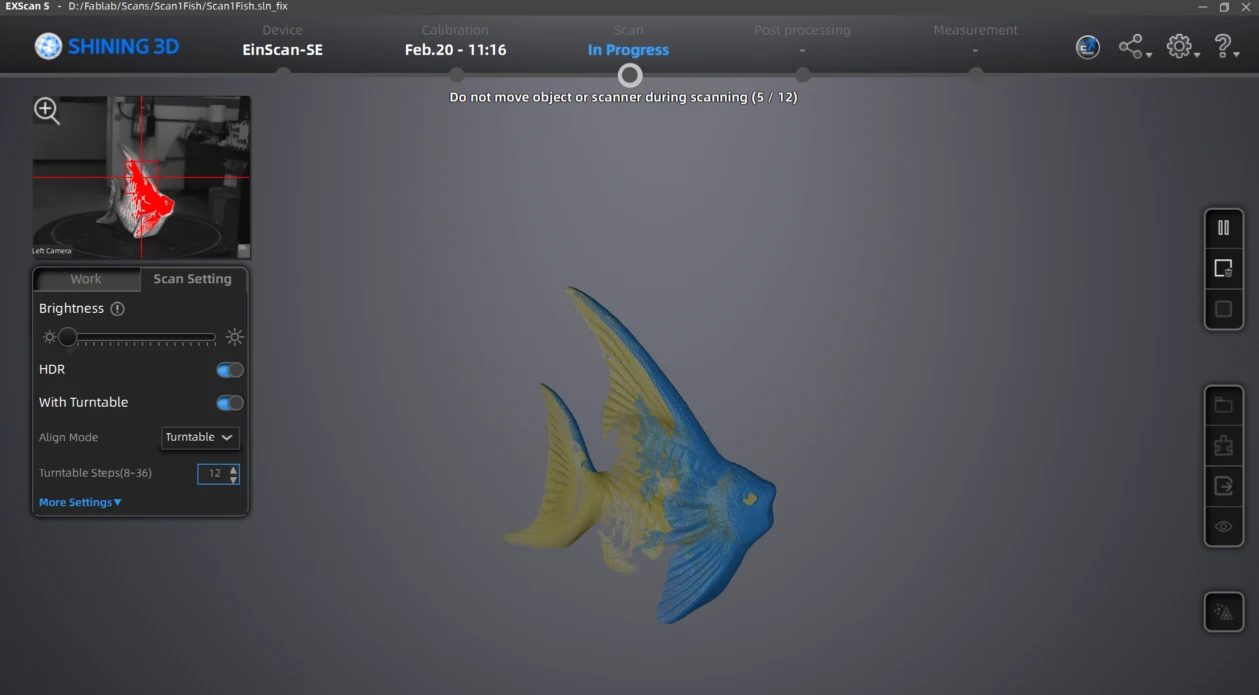
10. The scan will repeat the process the steps you selected , in this case 12.
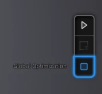
11. After the Scan is done, apply the edits and global optimization.In case there is blank information on your scan you can add another scan process and mesh them.
12. I did 2 more scans with the fish in different positions, as the top and bottom information was missing.
12.1 Here is how the second scan looks.
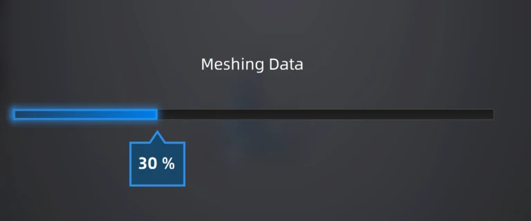
13. Once the scan is done mesh the model.
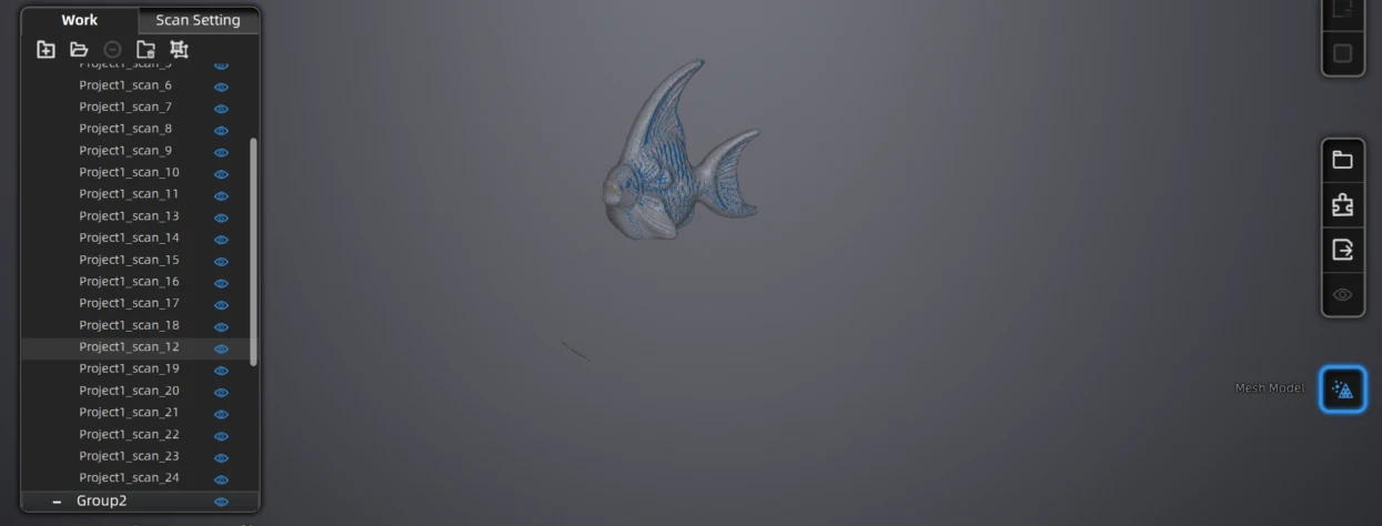
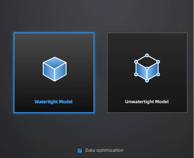
14. For meshing the program will ask you if you want a Watertight or Unwatertight model, the first one closed any holes your model had while scanning. I chose Watertight.
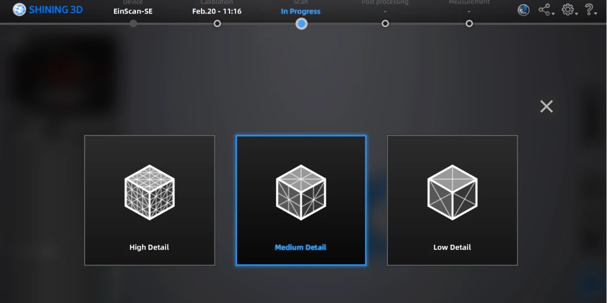
15. Then you can select the quality of the mesh (number of triangles) in this case I selected Medium Detail.
16. Afterwards you will have your model and select some post-processing tools like sharpen or smooth.
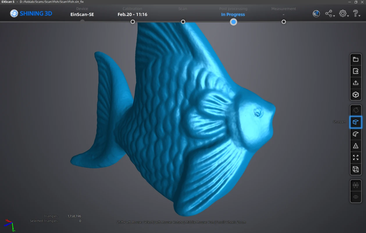
17.After post processing
Learning Outcomes
This week I deepened my understanding of 3D modeling and additive manufacturing by experimenting with both parametric and non-parametric workflows. Working with Maya allowed me to explore a more sculptural and organic approach compared to CAD-based modeling, helping me understand the differences in precision, control, and flexibility between both systems.
- Understanding joints and tolerances: I learned that hinge functionality depends heavily on clearance, thickness, and movement allowance. Even small dimensional adjustments (for example increasing hinge thickness in the Manta Ray) significantly improve durability. I still believe I can improve the shape, size, and movement behavior of the manta ray joints.
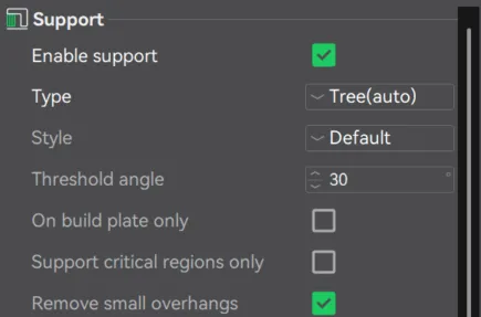
- Designing for 3D printing limitations: It is essential to consider tolerances, overhang angles, wall thickness, supports, and material behavior from the beginning of the design process. Designing without these rules leads to print failures or weak parts. Also 3D printing is an opportunity for object that are difficult to produce via subtracting manufacturing, such as the Manta Ray flexible print.
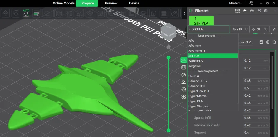
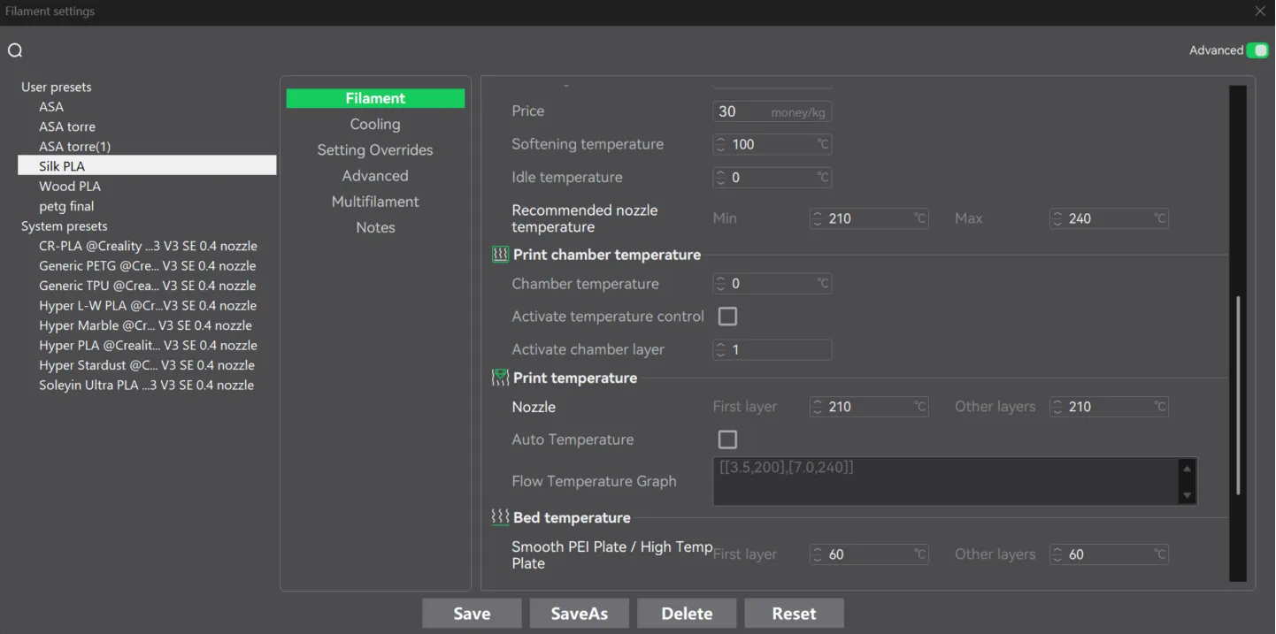
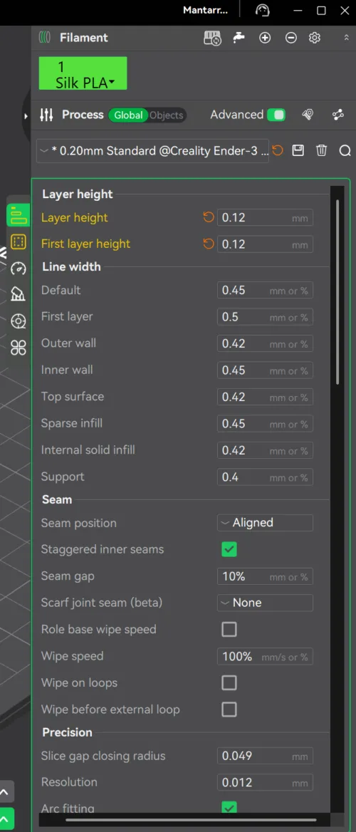
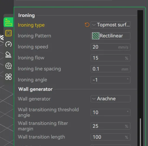
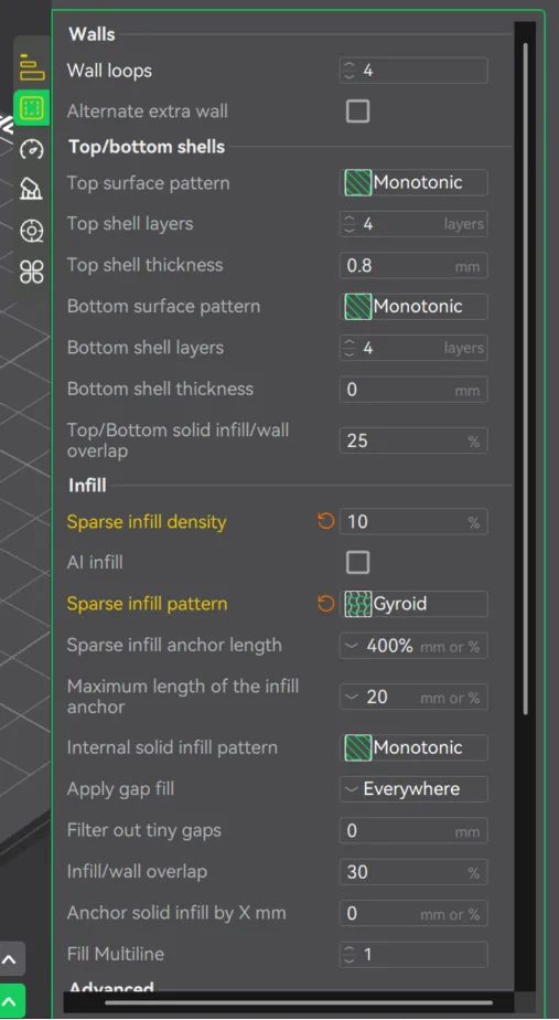
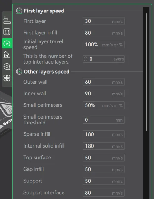
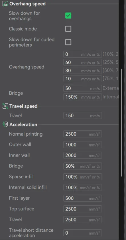
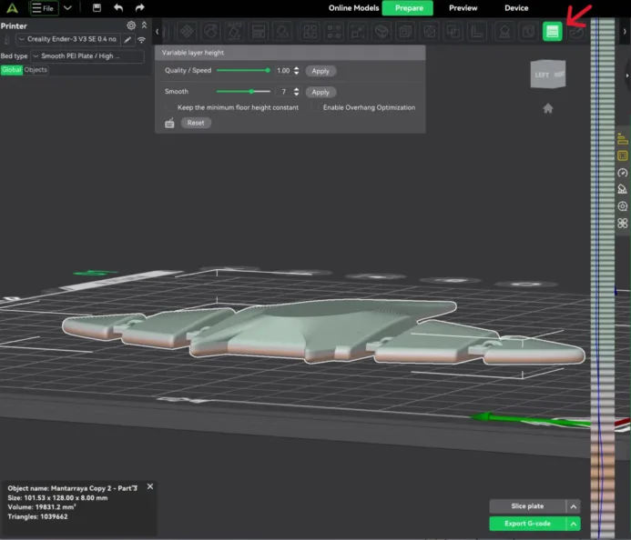
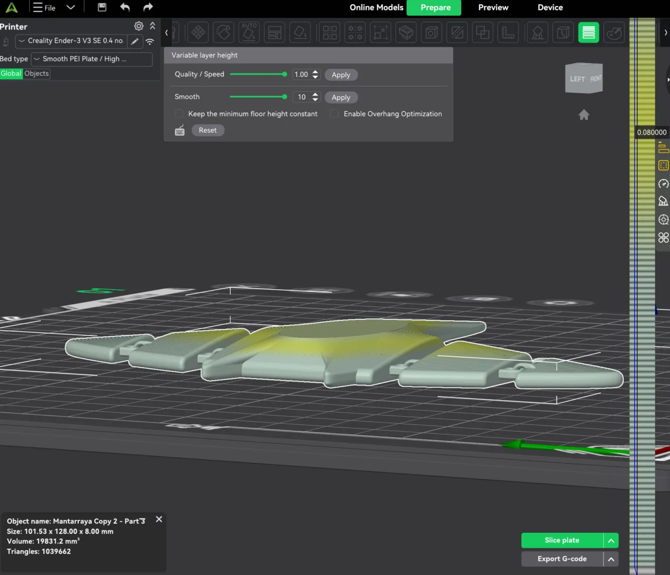
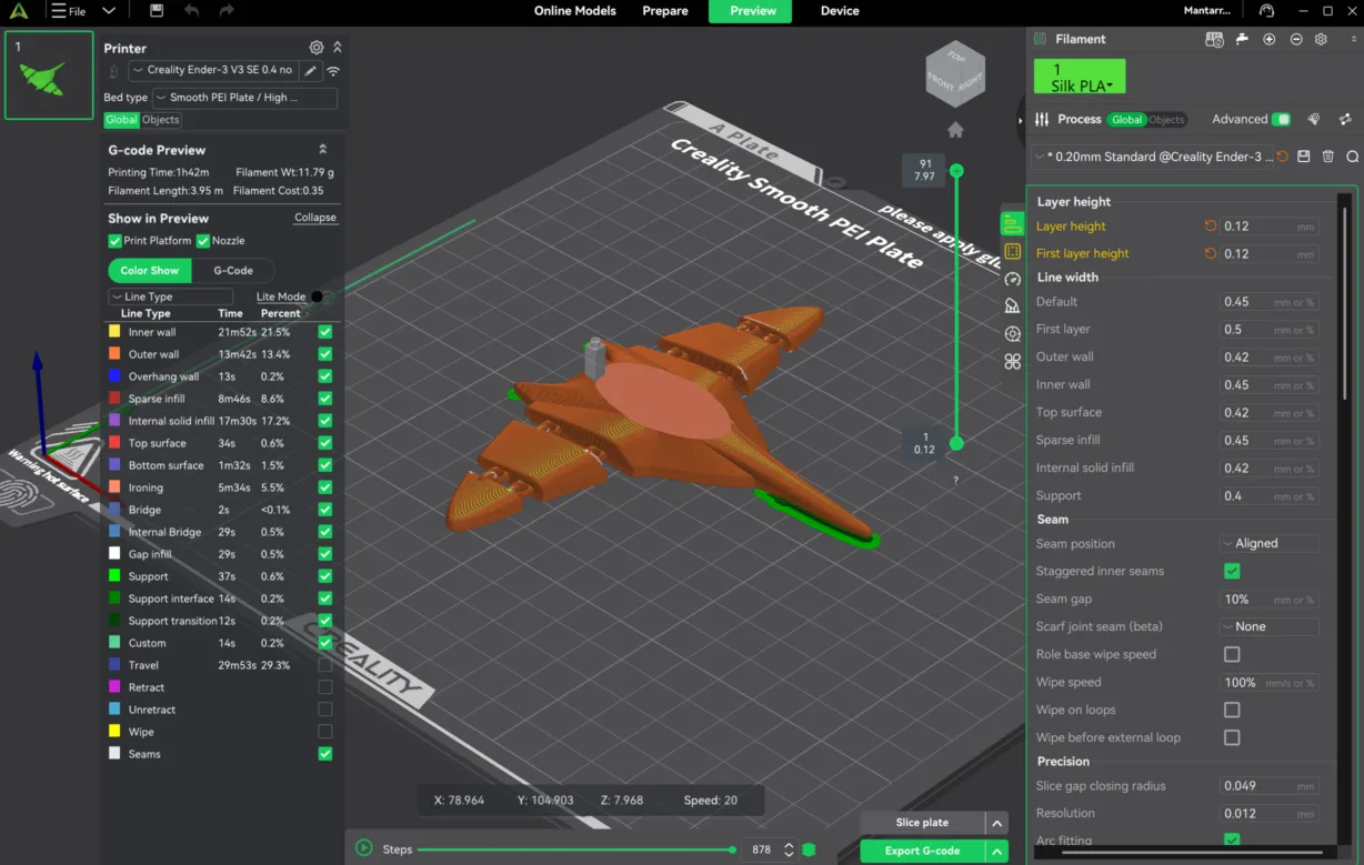
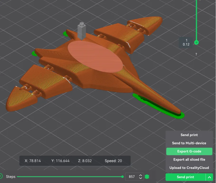
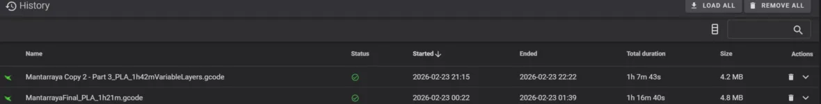
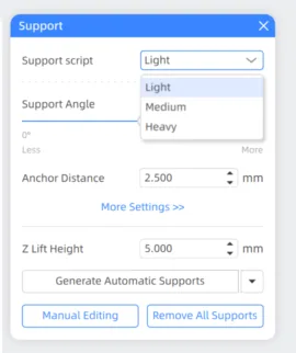
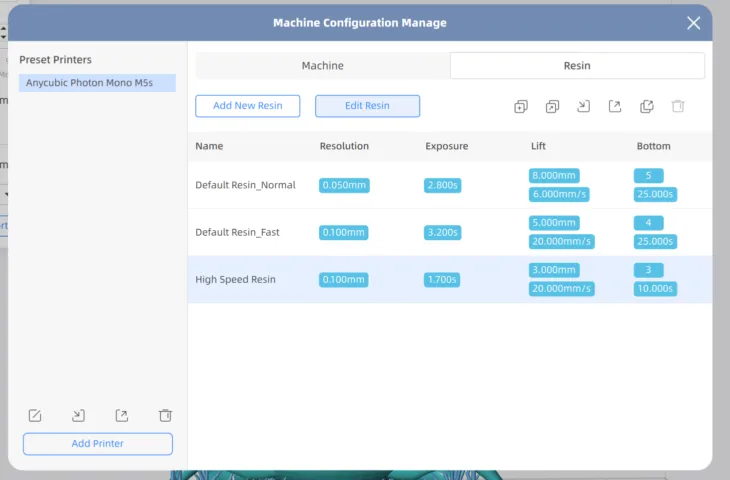
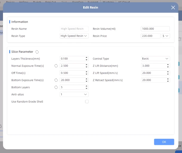
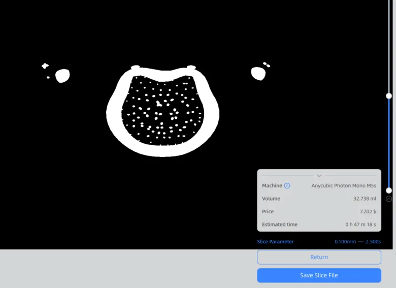
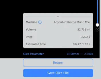
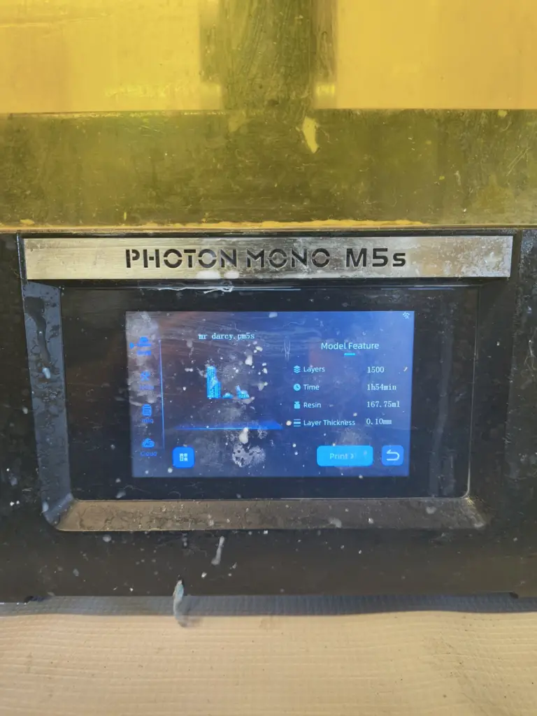
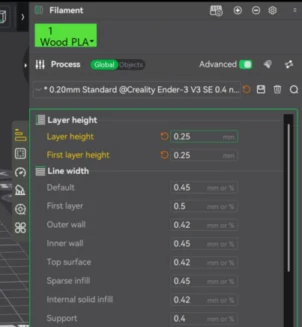
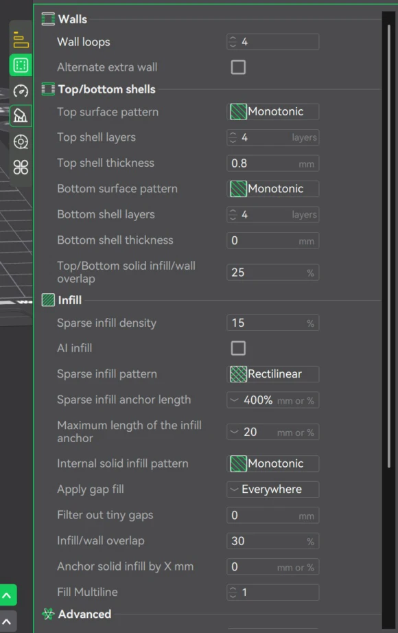
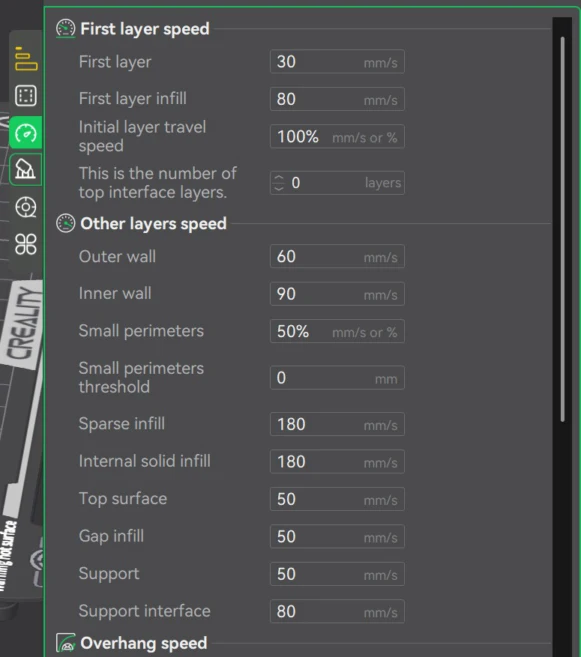
- Importance of slicing configuration: Print parameters such as layer height, variable layer settings, and exposure time (resin) directly affect print quality, material consumption, and production time. Optimizing these settings enables faster iterations and more efficient rapid prototyping.
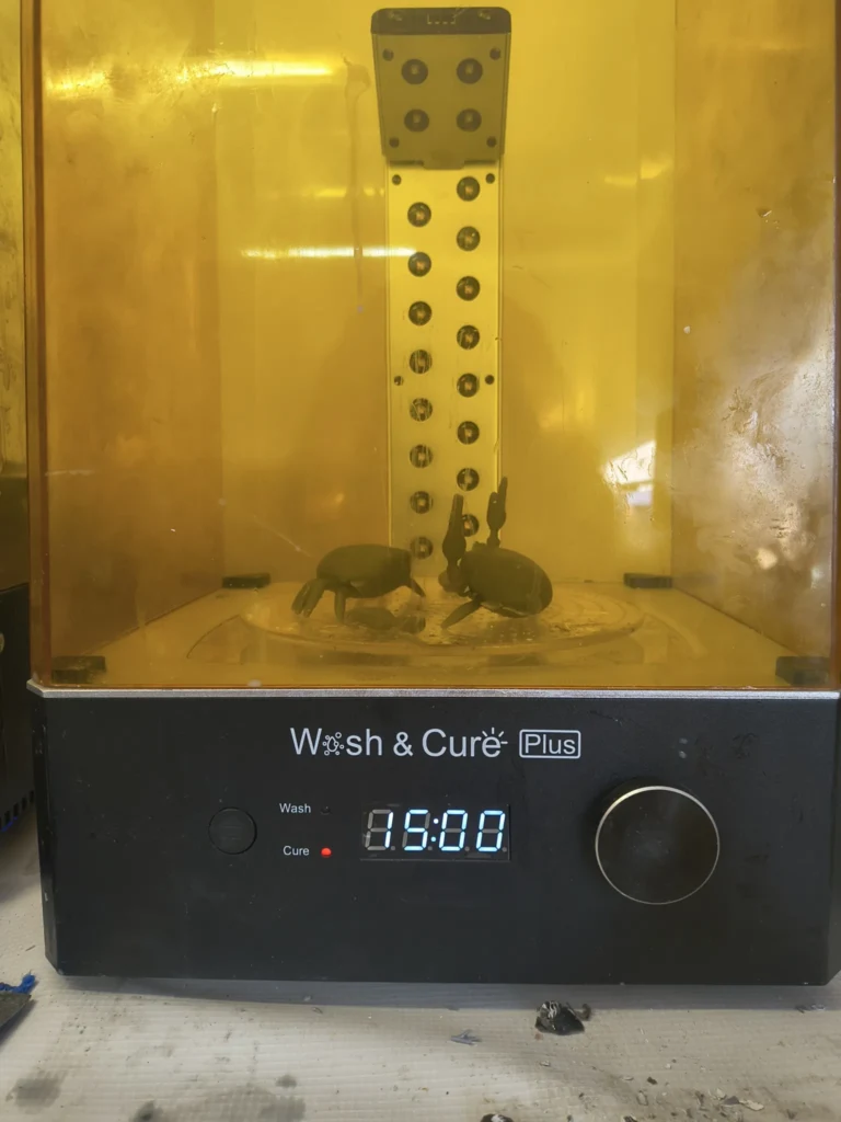
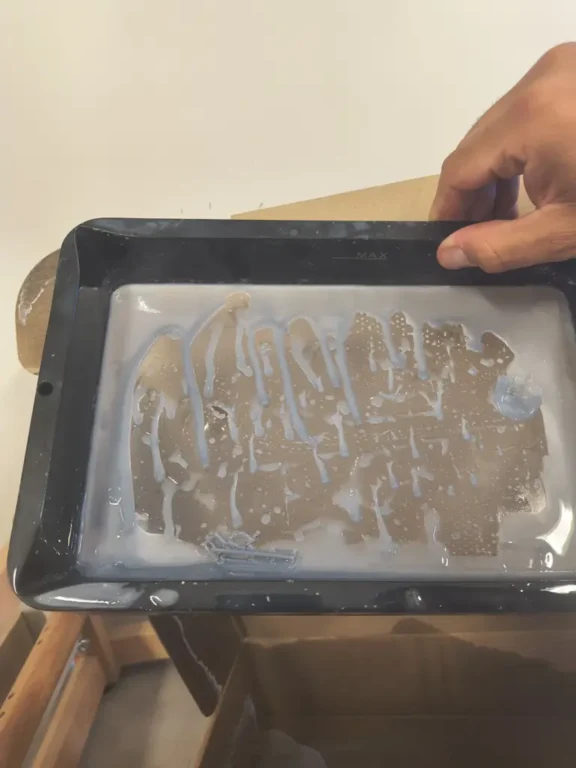
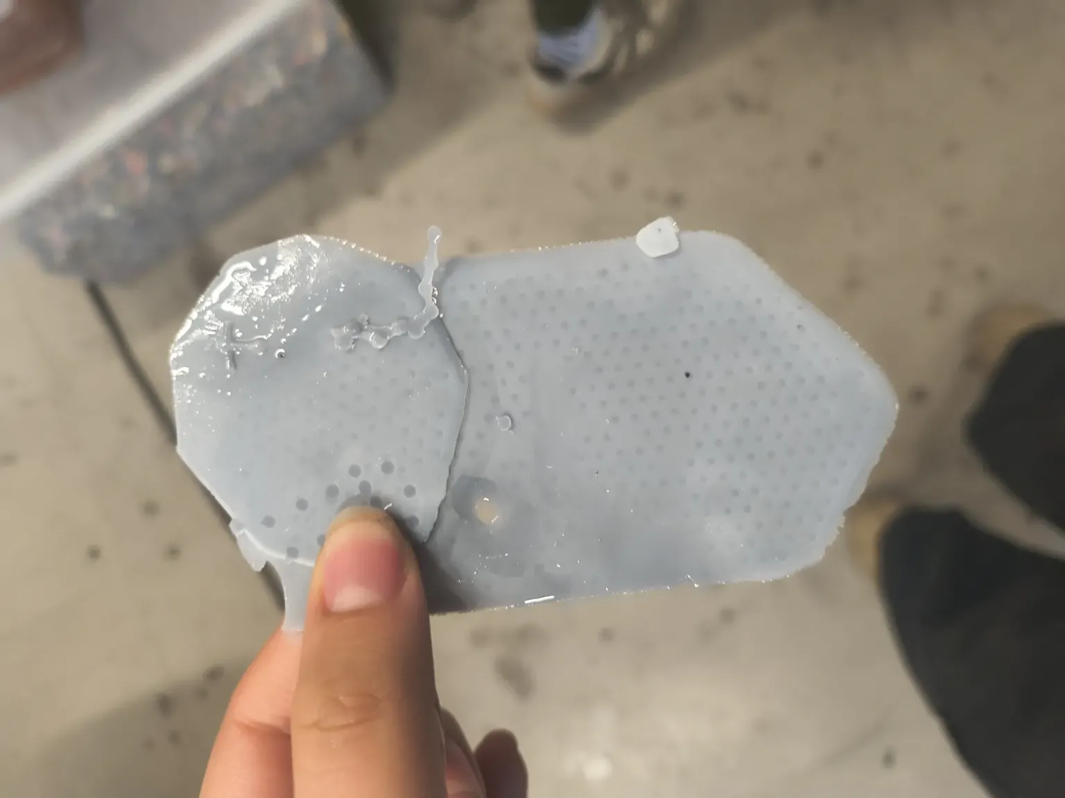
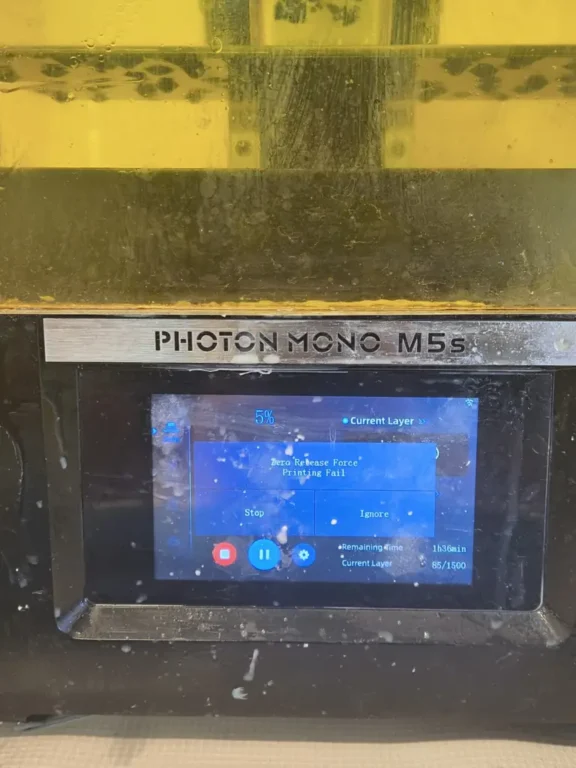
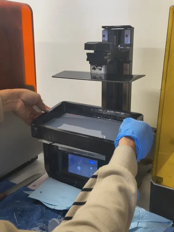
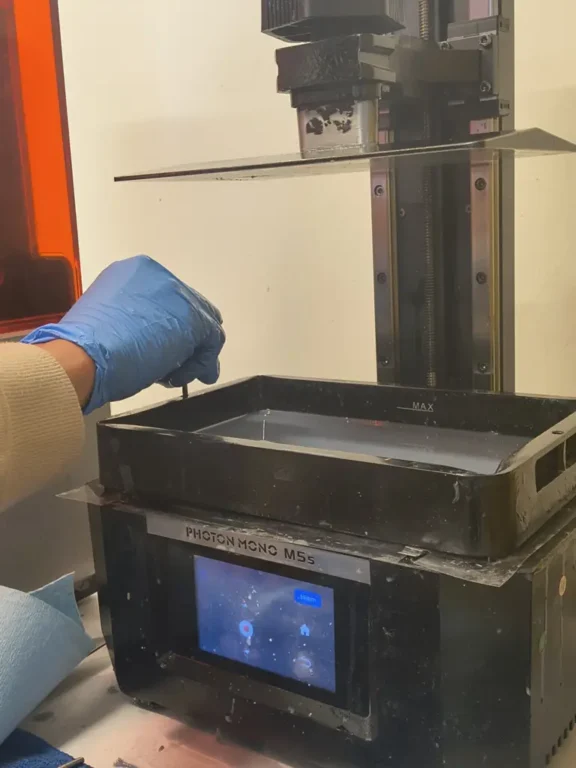
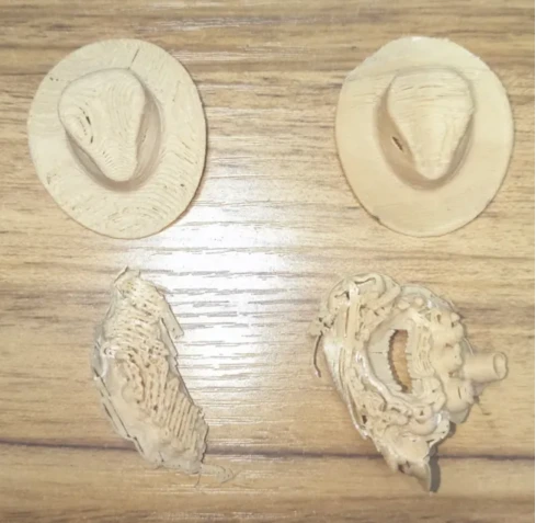
- Differences between FDM and resin printing: While resin printing provides higher resolution and surface detail, it introduces additional challenges such as membrane maintenance and suction forces. FDM printing is more accessible and forgiving, but requires careful attention.
- 3D scanning process: I learned that 3D scanning requires careful positioning, multiple captures, alignment, and mesh cleaning. The raw scan is rarely perfect and usually needs refinement before it can be used for modeling or printing.
- Iterative improvement mindset: Testing, failing, and adjusting parameters (like exposure time or hinge thickness) help me improve the final results, even if there are preset parameters is essential to do test as the same parameters might not work due different conditions (3D printer settings and filament).
Overall, this week re-enforced my ability to design intentionally for additive manufacturing instead of simply modeling shapes and hoping they print correctly. While learning the different approaches and applications additive manufacturing has.