9. Input Devices
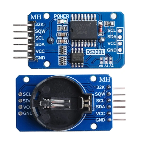
This week focused on input devices: sensors and modules that read information from the physical world and send it to a microcontroller. My assignment was to use an input device, measure and display data from it. I chose a DS3231 Real-Time Clock (RTC) module, which keeps precise track of date and time even when the main circuit is powered off. To connect it to my custom PCB (which I made in week 10), I also had to design and fabricate a small I2C adapter board, since my base PCB didn't include the pull-up resistors that I2C communication requires.
The general workflow this week was:
- Understanding what an input device is and how the I2C communication protocol works.
- Designing an I2C adapter PCB in KiCad (schematic + layout). Following the week 10 workflow.
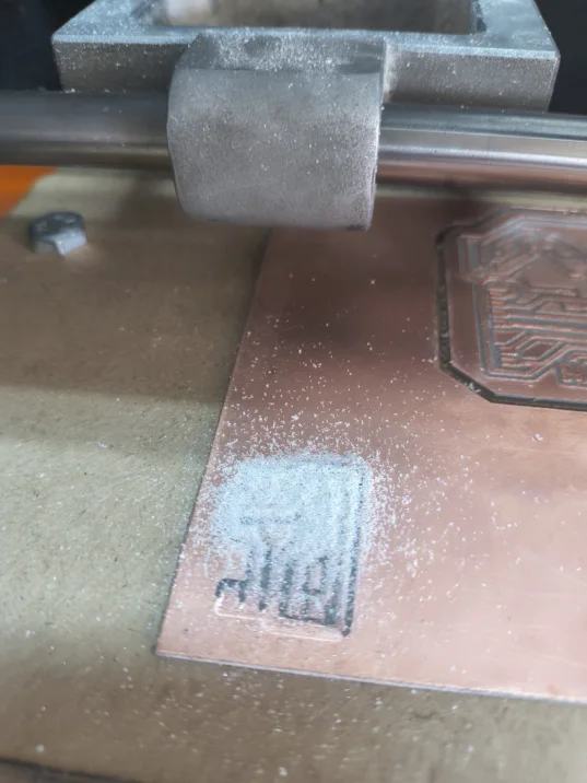
- Milling & Soldering the adapter
- Setting up the Arduino IDE with the XIAO board library and the RTC DS3231 library.
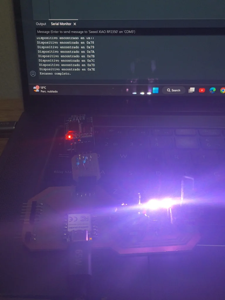
- Programming and troubleshooting: no communication, COM port issues, and false-positive I2C scan results.
To know more about different input devices and the I2C protocol, check out the group assignment.
Key Concepts
What is an Input Device?
In electronics, devices can be divided into two categories: inputs and outputs. An input device is any sensor or module that gathers data from the physical world and sends it to a microcontroller. Examples include: temperature sensors, buttons, microphones, cameras, light sensors, and clocks. The microcontroller reads that data and decides what to do with it, like turning on a fan when temperature is too high or displaying the current time on a screen.
This is the opposite of an output device (like a motor or LED), which receives a command from the microcontroller and does something in the physical world. A complete project usually has both: inputs that read data, and outputs that react to it.
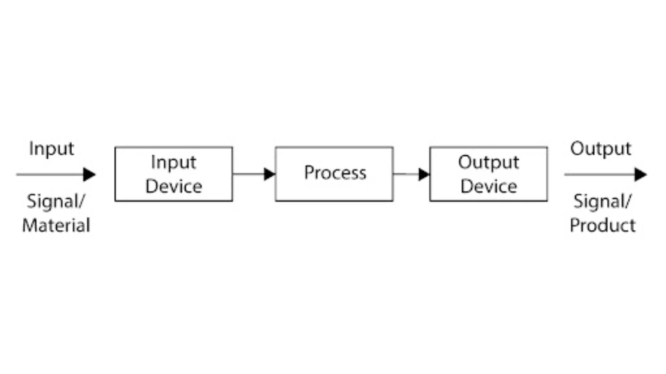
A diagram showing how a sensor (input) sends data to a microcontroller, which then drives an output device.
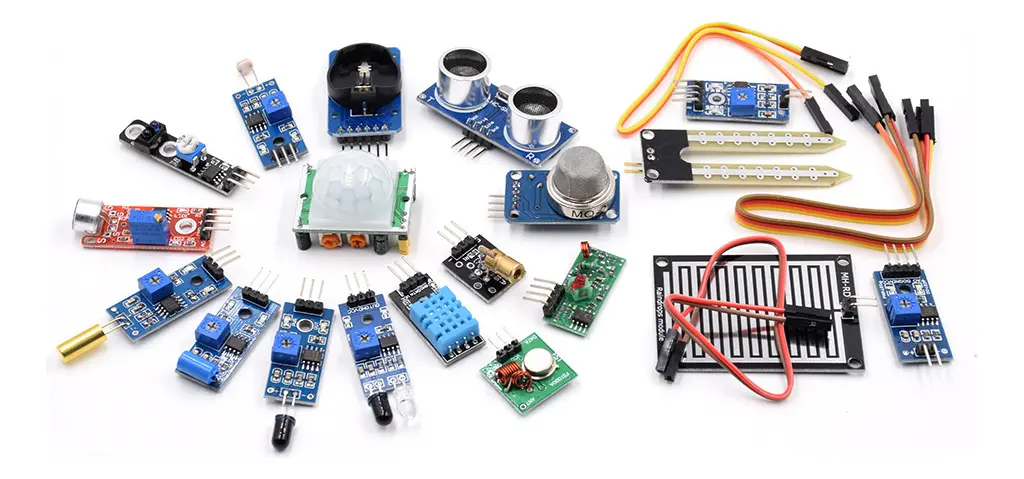
Examples of different input devices: temperature sensor, button, RTC module, and light sensor.
I2C Adapter PCB
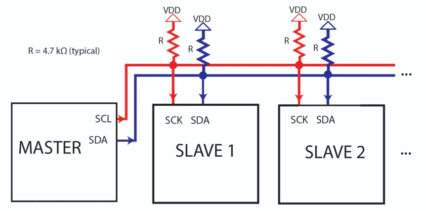
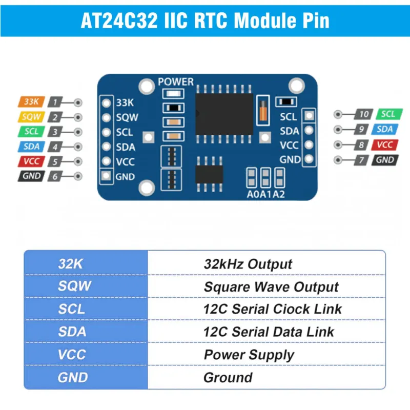
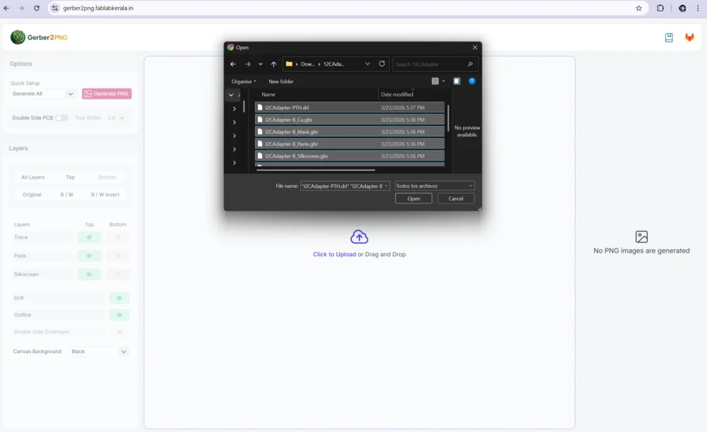
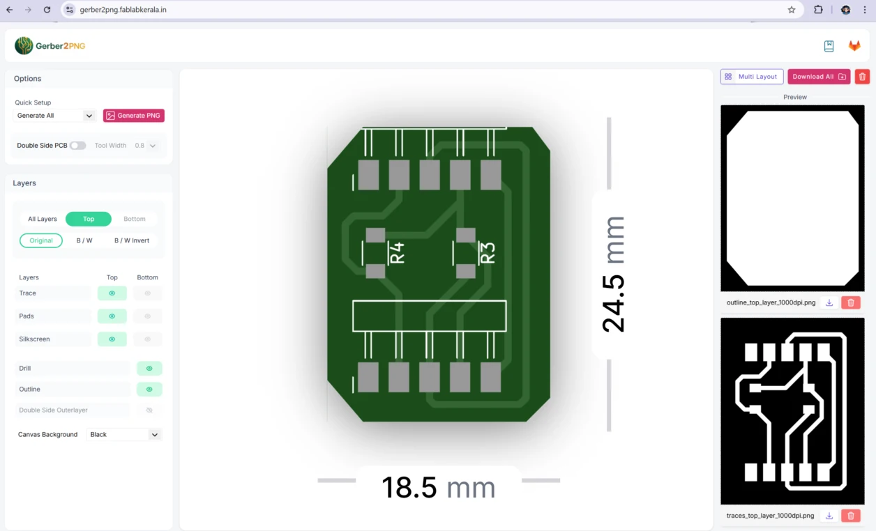
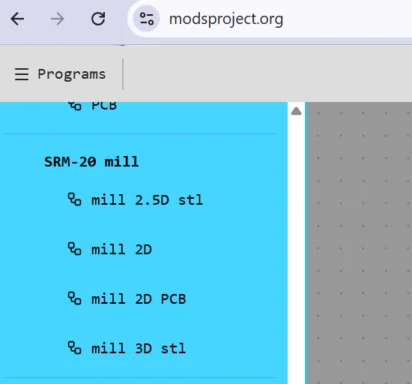
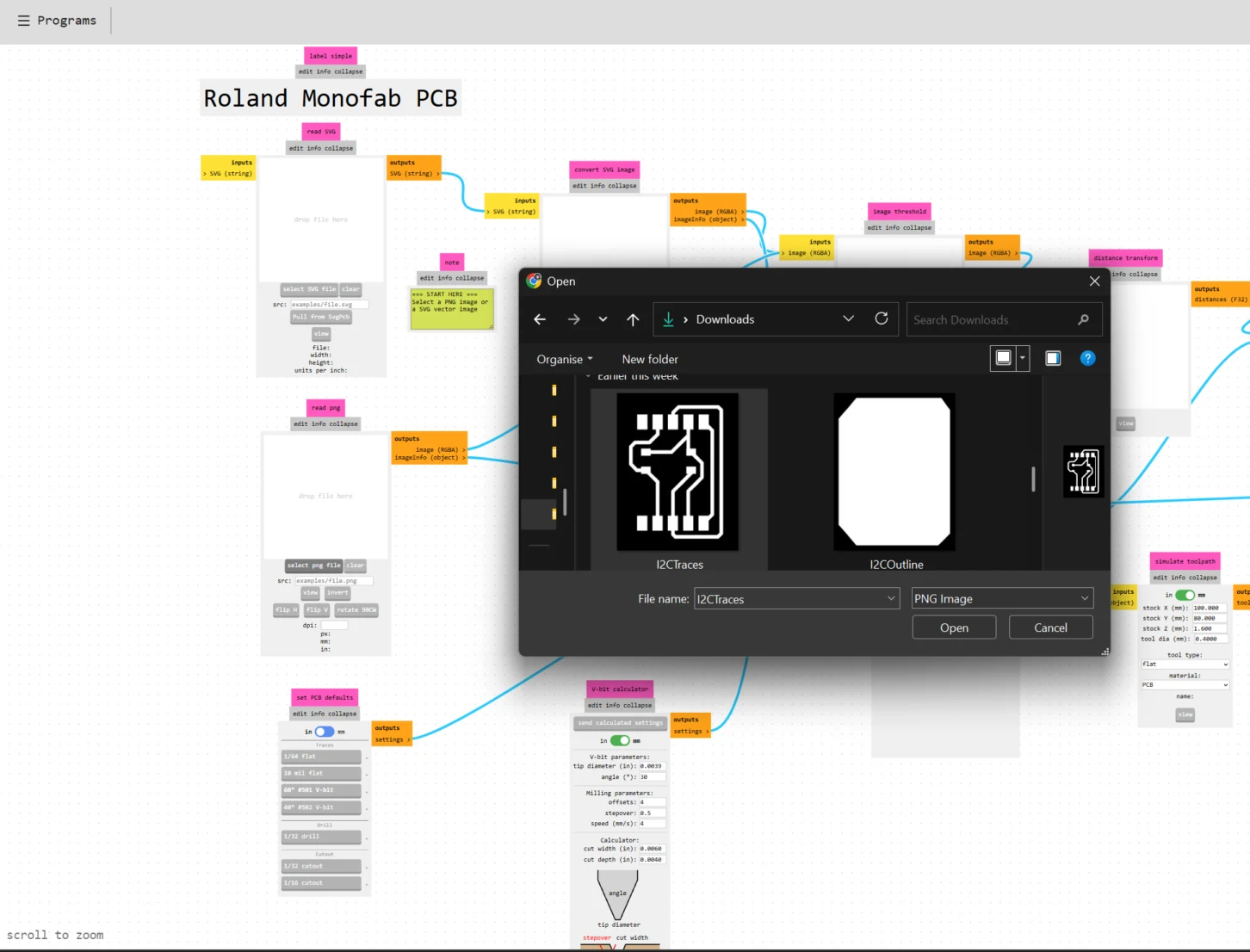
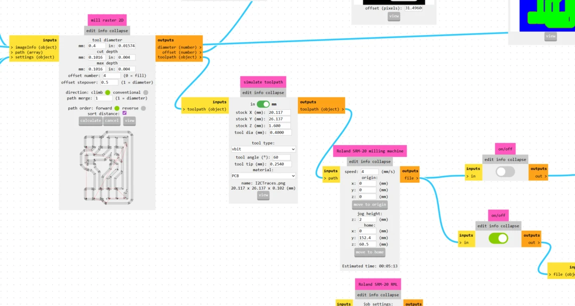
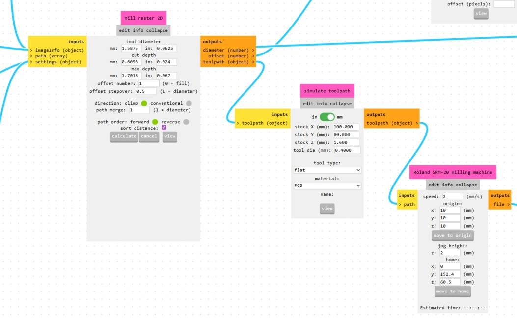
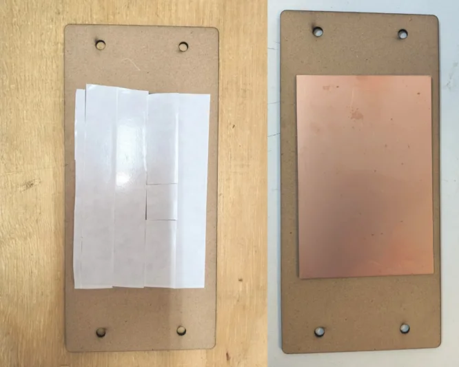
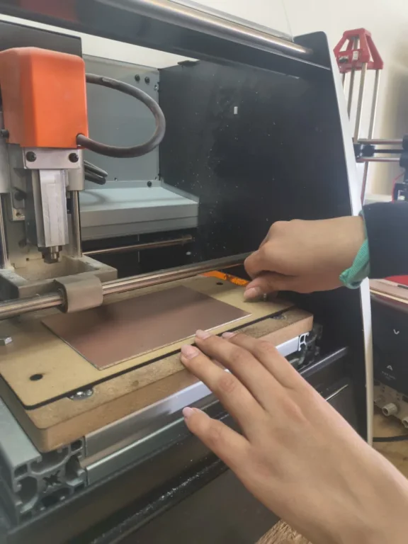
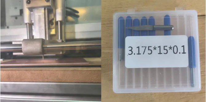
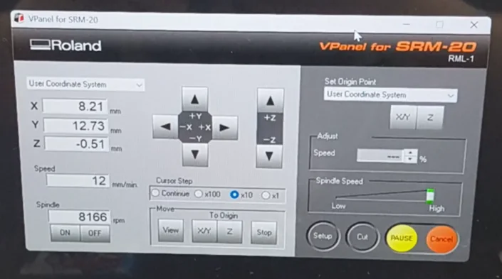
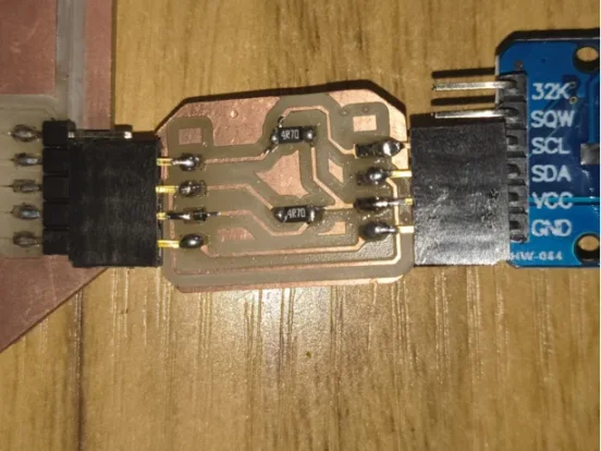
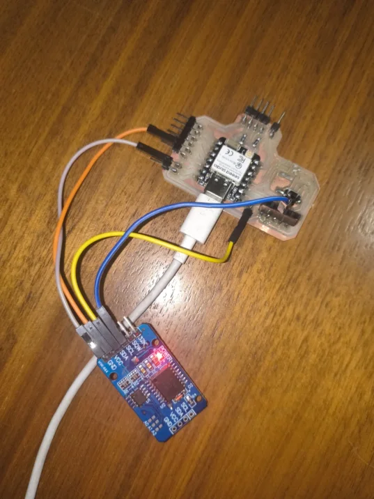
Since my base PCB from week 8 did not include I2C pull-up resistors, I designed a small adapter board in KiCad. This board adds the two 4.7 kΩ resistors on the SDA and SCL lines and breaks out the I2C connector so the DS3231 module can plug directly in. The design and fabrication process followed the same workflow as week 8: KiCad, Gerber2PNG, Mods Project, milling, and soldering.
I2C Adapter Design in KiCad
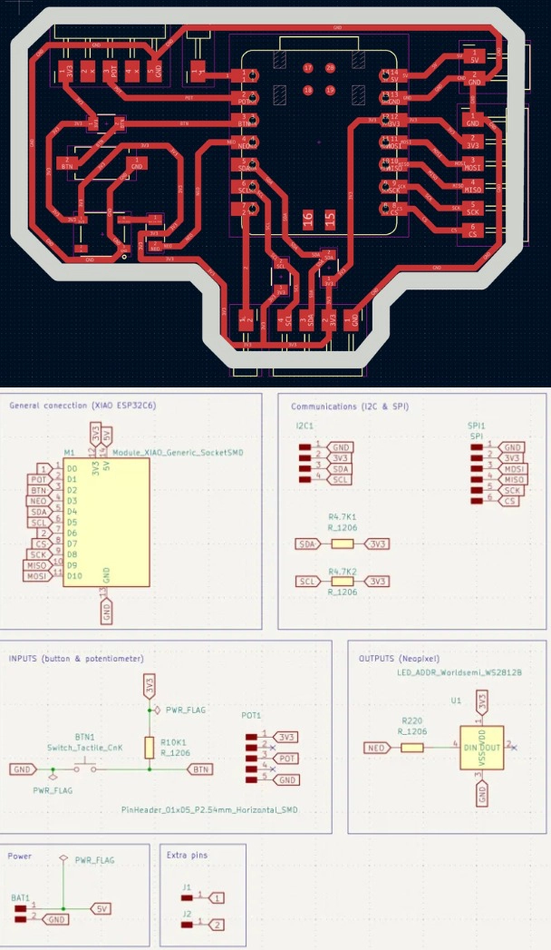
I designed the adapter from scratch in KiCad. The goal was simple: two pull-up resistors (4.7 kΩ each) connecting SDA and SCL to 3.3 V, plus a connector for the DS3231 module. The schematic defines the electrical connections, and the PCB layout defines the physical position of each component and the copper traces.
1. Here is the schematic in KiCad.The circuit includes two resistors (R1 and R2, both 4.7 kΩ) connecting the SDA and SCL to VCC. The J1 connector brings out VCC, GND, SDA, and SCL to the DS3231.
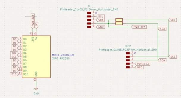
After running the ERC (Electrical Rules Check) to verify there are no schematic errors, I opened the PCB editor and placed the components. The board is small since there are only a few parts.
2. In the PCB editor, I routed the traces manually, each trace connects two pads following the schematic's netlist. I kept the board compact to fit the available space next to my main board.
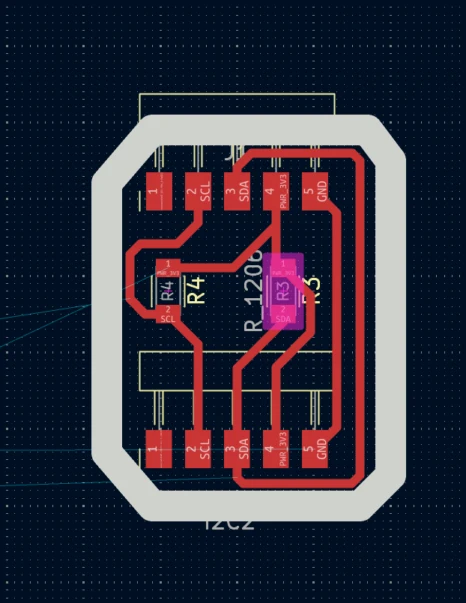
Then I ran the DRC (Design Rules Check) to catch any short circuits or clearance violations before exporting. It is important to fix all errors before generating files.
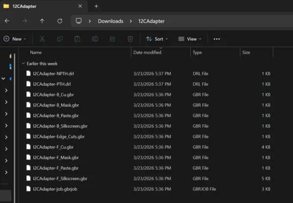
3. After routing the traces, I exported the Gerber files to do this go to File > Fabrication Outputs > Gerbers and select the copper layer (F.Cu) and the Edge.Cuts (board outline) layer.
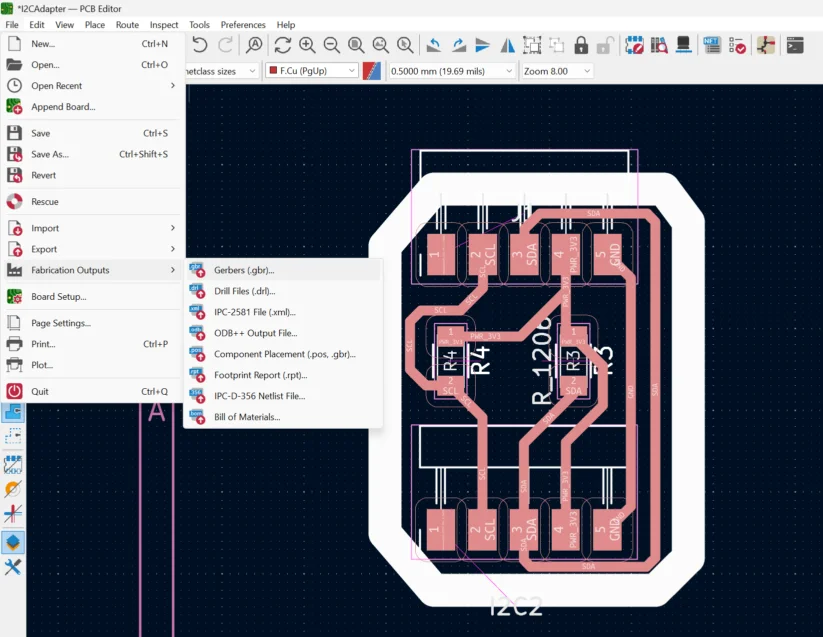
Save this files on a folder for future reference, as we will need them for the milling process.
Programming
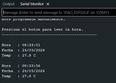
The programming consisted of writing a code for the XIAO microcontroller to read the time from the DS3231 and print it to the serial monitor. This required setting up Arduino IDE with the right board definition and library.
Setting Up Arduino IDE
Arduino IDE is a free software that lets you write and upload code to microcontrollers. Before using the XIAO board and the DS3231, two things need to be installed: the XIAO board library (so Arduino IDE recognizes the board and knows how to program it) and the RTClib library (which gives us ready-made functions to talk to the DS3231 without having to write all the I2C communication from scratch).
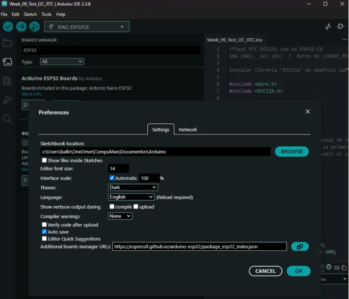
1. Open Arduino IDE. Go to File and select Preferences. In the "Additional Boards Manager URLs" field, paste the Seeed XIAO board URL. This allows the Boards Manager to find the XIAO package. In this case I used the XIAO ESP32C6 board URL: https://espressif.github.io/arduino-esp32/package_esp32_index.json
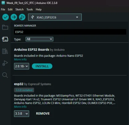
2. The go to Tools select Board and click on Boards Manager. Search for "Esp32" and install the board package by Espressif Systems. This adds the XIAO family to your list of available boards.
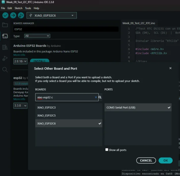
3. After installation, go to Tools then Board and select your specific XIAO model. Make sure to also select the correct port.
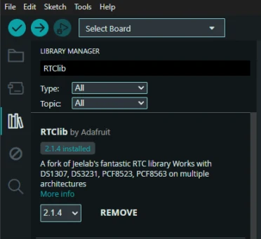
4. Install the RTClib library: go to Sketch thenInclude Library and select Manage Libraries. Search for "RTClib" by Adafruit and click Install. This library includes functions for the DS3231.
Learning Outcomes
This week pushed me to understand not just how to follow a process, but why each step matters and what happens when something goes wrong at a component level.
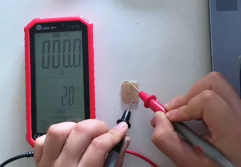
- Always verify component values before soldering: The 4.7 Ω vs 4.7 kΩ mistake cost significant time in desoldering and rework. SMD resistor codes are small and easy to misread. Using a multimeter to verify before placing the component is a habit I will keep from now on.
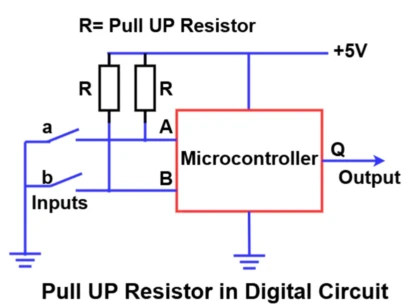
- Pull-up resistors are not optional for I2C: I now understand why they exist. Without them, the SDA and SCL lines have no defined resting state and communication is impossible or unreliable. The value matters too, if its too low (4.7 Ω) clamps the line too hard; too high and the signal rise time becomes too slow for the clock speed.
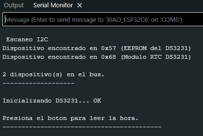
- False positives in I2C scanning indicate a signal problem: Seeing random addresses on the scanner is a red flag. It means the bus is noisy or the pull-ups are not doing their job. A healthy I2C bus should only show the addresses of real, connected devices.
- Documentation of failures is as important as documentation of successes: Every error I hit this week gave me a deeper understanding of how I2C works than if everything had worked perfectly on the first try.
The next step is trying to connect more I2C devices like an OLED display that shows the real time, so there is a visual output not just in the serial monitor.