This week we learned about parametric design and its application to computer-controlled cutting,
principally in laser cutting and vinyl cutting.
Laser Cutting
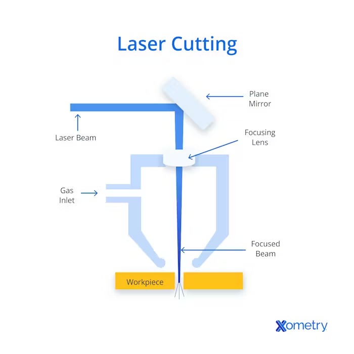
Laser cutting is a thermal, non-contact process that uses a high-powered, focused laser beam.
It is normally used to engrave and cut different kinds of materials, like metal, plastic, or wood.
It works thanks to a CNC (Computer Numerical Control) software, which indicates the digital pattern
the laser beam must follow. While the beam traces the path, a coaxial gas jet (oxygen or nitrogen)
blows away burnt material, leaving clean, finished edges.
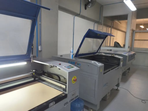
At Fab Lab Puebla, we have 3 different laser cutters from CAM Five: the CFL-CMA1200,
CFL-CMA1080K, and CFL-CMA 1309T. To learn more about them and laser cutting check the group assignment.
Here is how I configured the CFL-CMA1080K laser cutter:
Set Up
In this diagram we can see the principal components of laser cutters in general.
Followed the three CAM Five laser cutters available at Fab Lab Puebla.
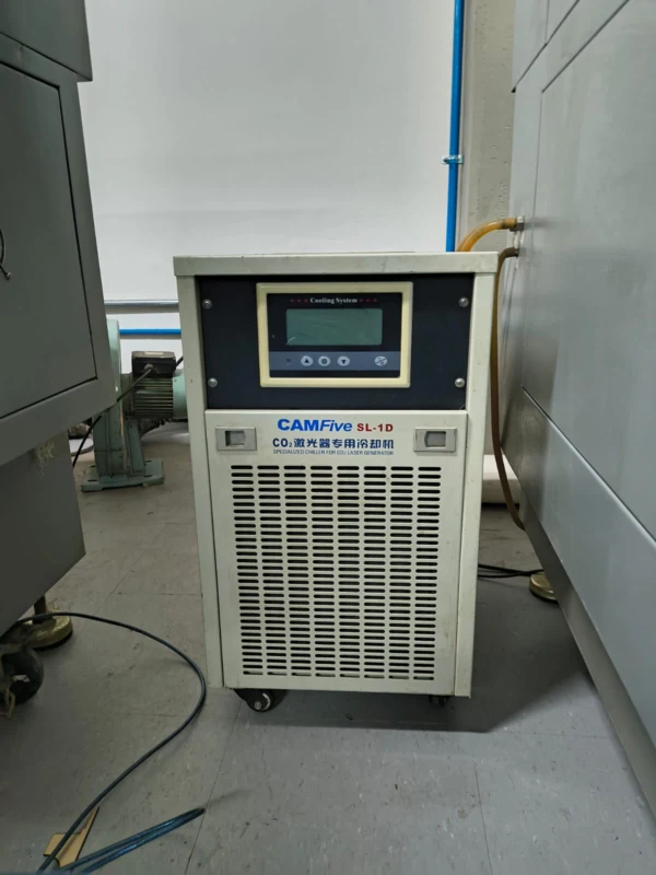
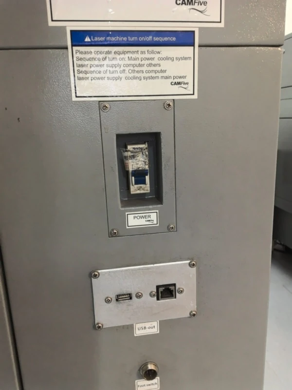
1. Check that the machine chiller is on , it regulates the machine temperature for a safe workspace.
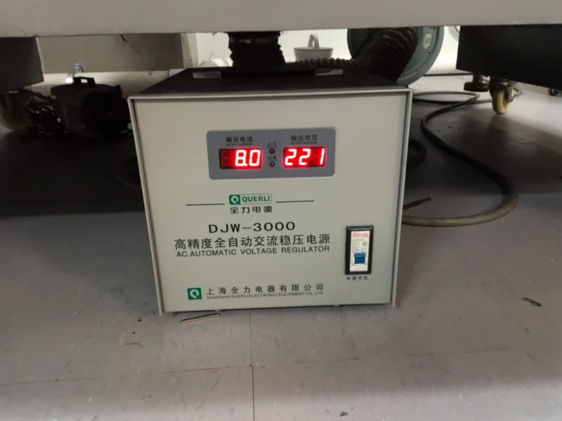
2. Turn on the automatic voltage regulator.
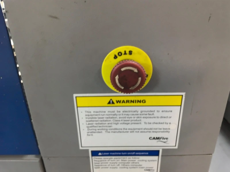
3. Turn on the machine switch and release the safety button.
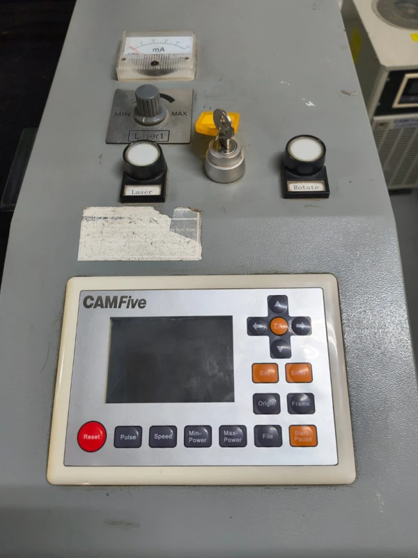
4. Insert the key, turn on the laser, and move it to max.
5. Final step , machine fully ready for operation.
The origin is normally at the top right corner, but it can be repositioned using the panel control arrows followed by the origin button.
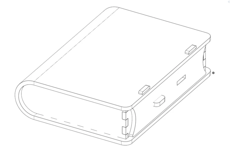
Parametric Kit – Card Game Box
For this exercise I designed a box for card games in Onshape. This box uses a flexible hinge, finger joints, and a sliding locking mechanism based on "Flexible book boxes" I found on the internet and Pinterest. I modeled all pieces using parametric variables. Here is the complete design process step by step.
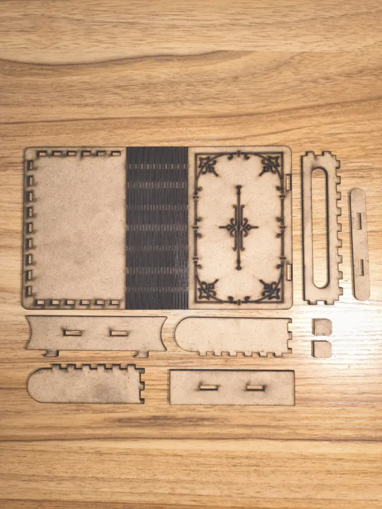
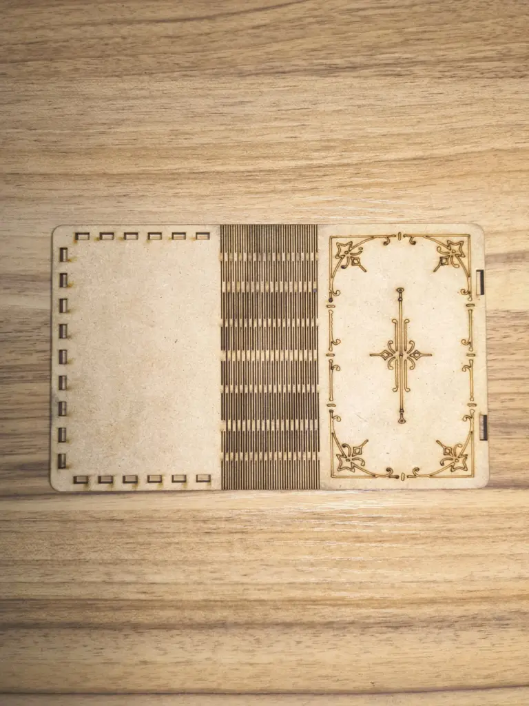
All cut pieces laid out , ready for assembly.
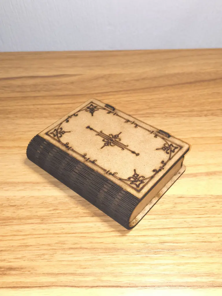
Hero shot of the assembled card game box.
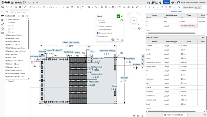
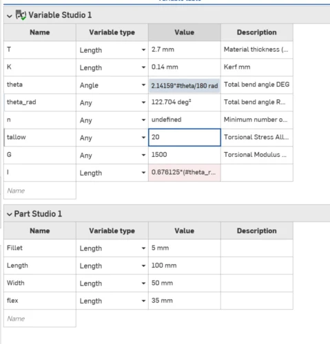
1. Created a new document (Week 03), started a sketch on the Top Plane, and drew a rectangle with rounded vertices using the fillet tool. Variables were created with the # symbol when dimensioning.
2. The variable table , I tried creating one just like in SolidWorks, but two variables gave "error regenerating." The flex hinge first attempt also snapped on a quick laser test.
3. After researching, I found a YouTube video with flexible hinge samples and bending radii. A 1 mm distance worked perfectly. I drew 4 lines per section and used a linear pattern.
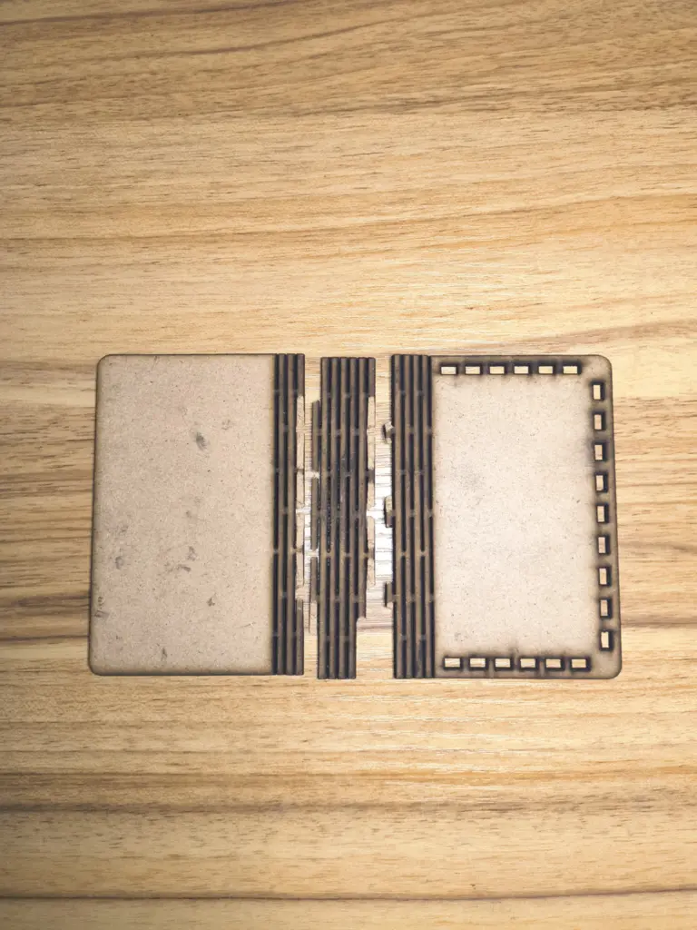
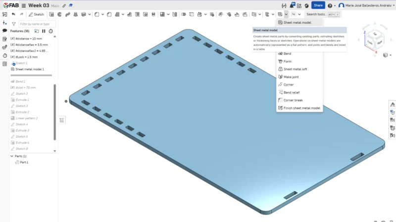
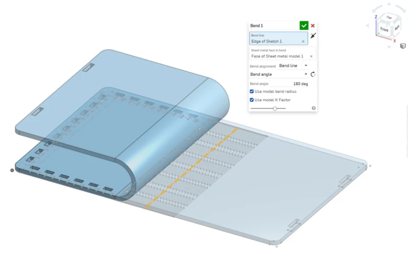
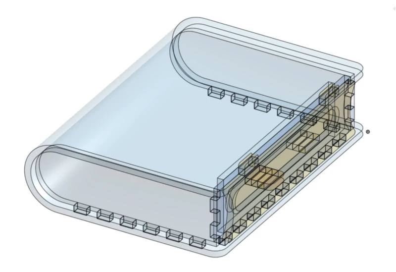
4. Used the "Sheet metal model" tool to apply a bend on the center line of the flex hinge, which lets me visualize the folded result in 3D.
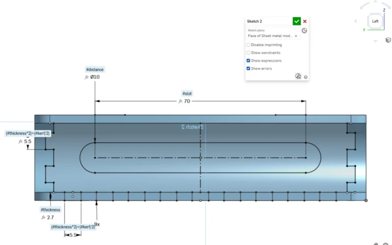
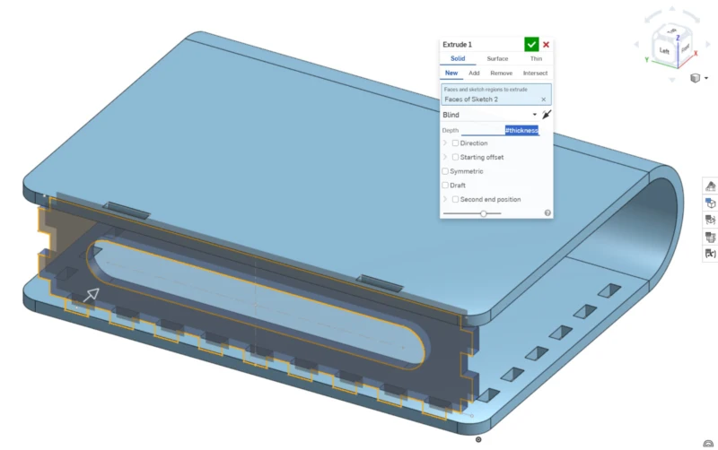
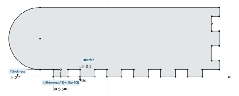
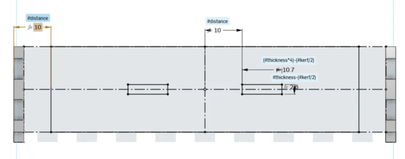
5. Used the "Use" tool (u) to reference the finger holes of the book paste, drew the front piece rectangle with height = thickness and length = (thickness×2)+(kerf/2).
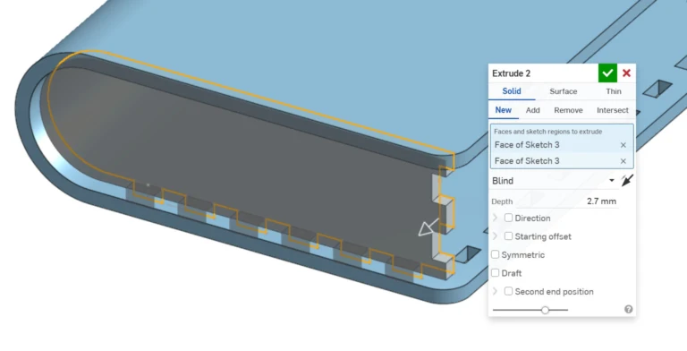
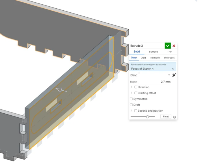
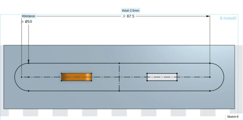
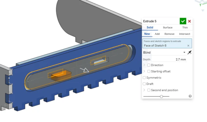
6. Added a slot for the sliding mechanism, used trim (m) to remove extra lines, then extruded the piece.
7. Continued modeling the remaining pieces using the same logic , drawing joints based on previous pieces and assigning sizes from existing variables.
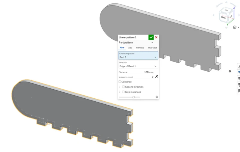
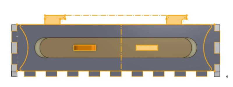
8. For repeated sides I used the 3D linear pattern tool, assigning the length of the piece. This step can be skipped if you don't need the 3D model with all pieces.
9–10. Continuing the assembly of all box sides, referencing previous pieces at each step.
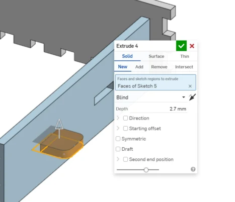
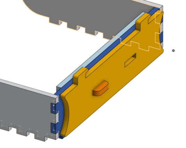
The sliding mechanism has 5 pieces: a base, sliding bolt latch, slot guide, and 2 connecting pieces.
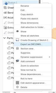
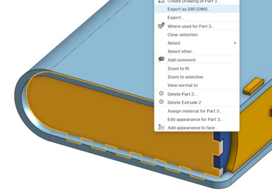
Exporting the DXF files. Right-click the face of each part and select Export DXF. Use DXF format, version 2000, in millimeters.
All exported files ready. I exported them separately so I can re-export only the piece that changes when I update a variable.
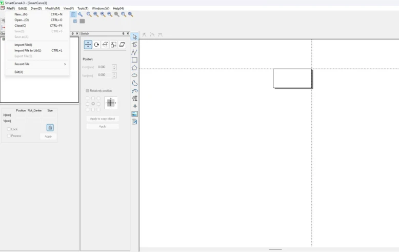
Laser Cutting Workflow in Smart Carve
To laser cut, we need to import our files to Smart Carve software. A USB security dongle is required to open the program. Here is the full workflow:
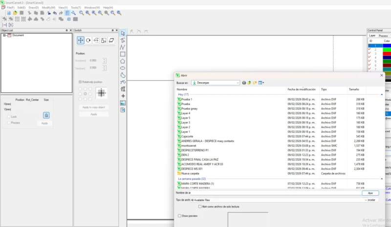
1. Open Smart Carve (USB dongle required), go to Menu → Import File. The program will ask for units , select millimeters.
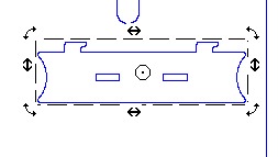
2. Repeat the import process for each file. Pieces will appear at the origin , you'll need to arrange and rotate them to fit your material workspace.
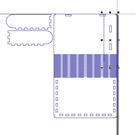
3. You can switch between move and rotation with a right click. Arrange all pieces to use the material area efficiently.
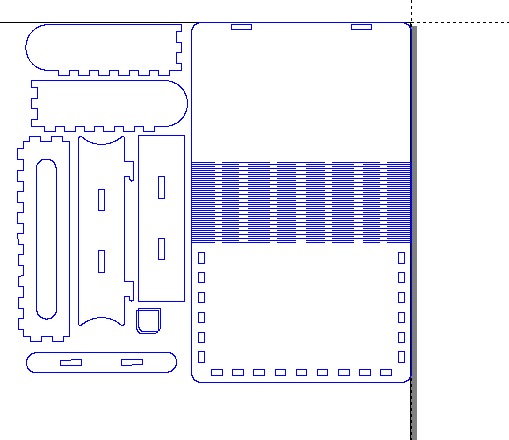
4. Final arrangement of pieces on the material area.
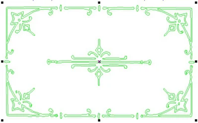
5. I also added a decorative pattern to engrave. I used the image trace tool in Affinity to vectorize a pattern I liked, just like in Week 02.
6. Importing the vectorized pattern into Smart Carve.
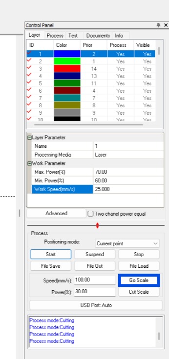
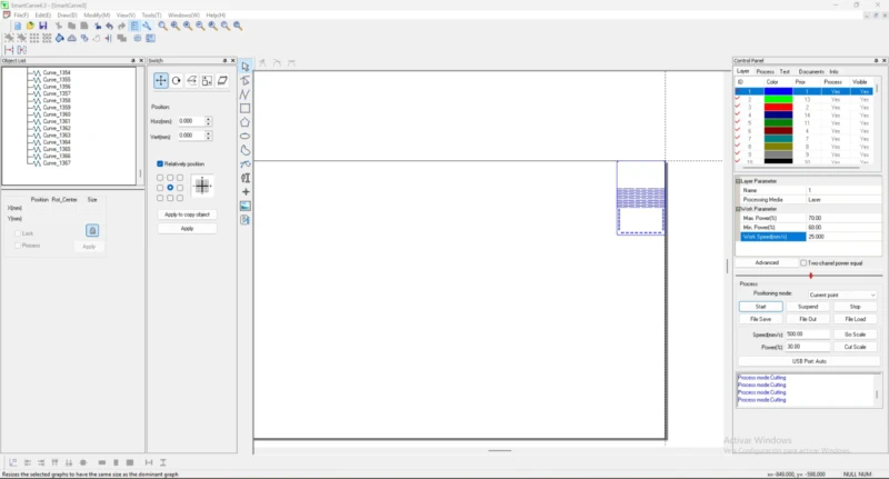
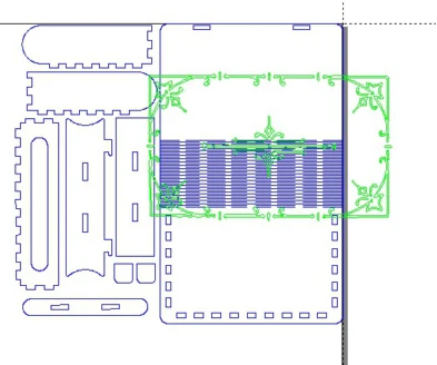
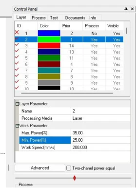
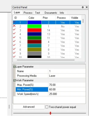
7. Selected the pattern group and changed it to a different ID process to set separate parameters for engraving and cutting.
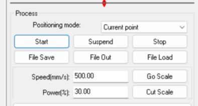
9. Use "Go Scale" to preview the working area. First run: only the engrave ID active to test the result without wasting time on a full cut.
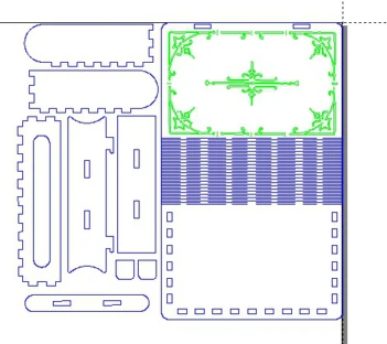
10. Once the engrave looked good, I disabled the green ID and enabled the blue one to perform the cut. The machine remembered the same origin so both processes align perfectly.
Technical Issues
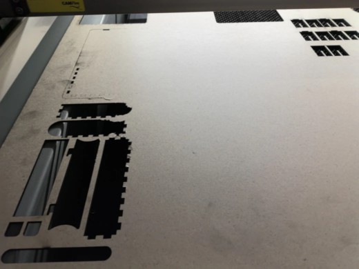
Sometimes the material doesn't cut completely. Here are the main causes and how to address them:
Warped material: If the material is warped it will have different distances to the nozzle, creating uneven cut depths. Always select a flat sheet with low warping.
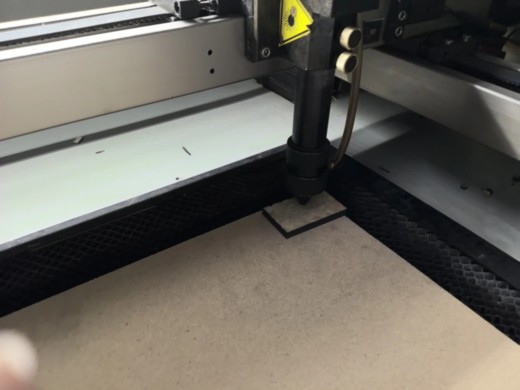
Nozzle misalignment: The nozzle can be too close or too far from the material. Ideal distance is 5 mm , use the small MDF rectangle provided in the lab as a calibration gauge.
Incorrect power parameters: Parameter tests help here. A second pass can solve the problem if parameters are close to what's needed; otherwise you'll need to adjust them.
Material thickness variation: The same parameters can have different results on different MDF qualities. Update the thickness variable in your file, export again, and redo the Smart Carve process.
Kerf and Precision
Kerf refers to the material removed by the laser beam. Measuring kerf is essential for accurate
fitting and assembly. To measure it, we drew a rectangle with lines, cut it, and measured the gap.
We divided the result by the number of lines we drew (in this case 10), so we got
1.38 mm / 10 = 0.138 mm of kerf. You can see more about it on the group assignment.
Male joints: add half kerf to each side
Female joints: subtract half kerf from each side
Vinyl Cutting
Vinyl cutting follows the same CNC logic as laser cutting, but instead of using a focused beam,
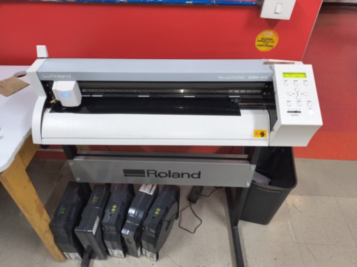
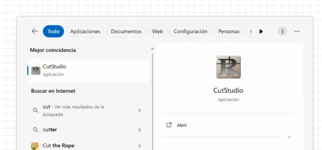
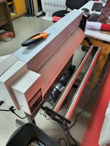
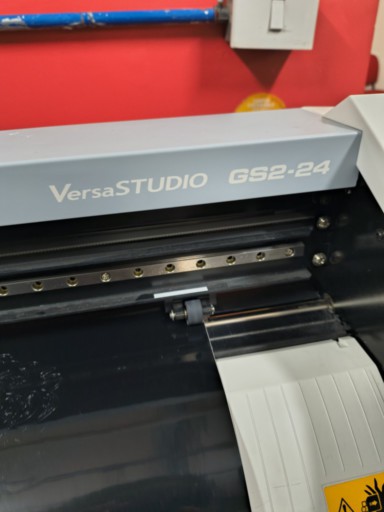
it uses a knife. For this exercise I used the VersaSTUDIO GS2-24 from Roland and the Cut Studio software.
Machine & Setup
Before sending the file, the vinyl cutter must be loaded and ready. We used a full vinyl roll secured with clampers.
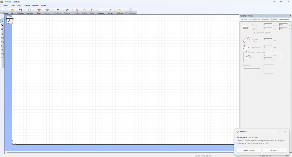
The VersaSTUDIO GS2-24 from Roland and the Cut Studio software interface.
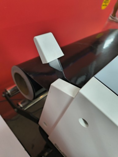
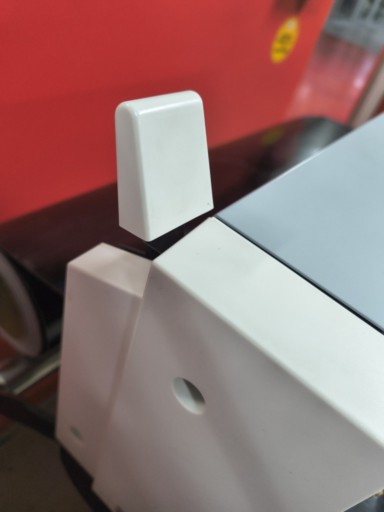
1. Load the vinyl roll , we used a full roll since there were no scraps available.
2. Secure the roll using the clampers. Pull the handle to lock the material , if not secured, it may shift and cause cutting errors.
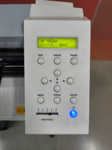
Machine control panel , pen force and origins were already configured for this exercise.
Machine fully loaded and ready to receive the cut file.
Importing Files into Cut Studio
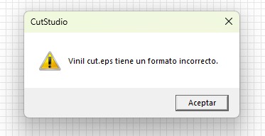
The recommended formats for Cut Studio are EPS (auto-outlines the cut path) or JPEG (requires manual outline extraction). I had issues with EPS exported from Affinity, so I used JPEG instead.
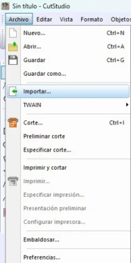
1. Importing the file into Cut Studio , File → Import.
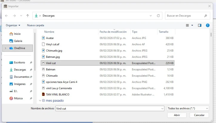
2. File selection dialog in Cut Studio.
3. The EPS format warning from Cut Studio when importing Affinity-exported files , even after changing export settings, the result was the same.
4. Importing as JPEG worked correctly. The image appears on the Cut Studio workspace.
Creating the Cut Outline
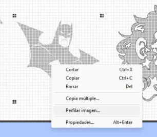
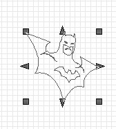
For JPEG files, select the image, right-click and choose "Perfilar imagen" (outline image). This opens a window where you can choose the final result , image + outline or just the outline. Then adjust the size using the size and form window.
1. Right-click the image → Outline image. The outline extraction window opens.
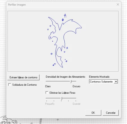
2. Preview of the extracted outline , you can choose to keep the image, the outline, or both.
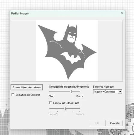
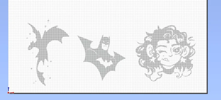
3. Adjusting the size using the size and form window. I used the total material area and repeated my designs at a smaller scale.
4. Final layout,all designs placed and ready for the cut.
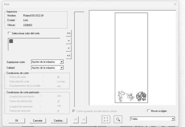
5. Go to File → Cut. A preview window shows the pattern and workspace. If everything is correct, press OK.
Cutting Process
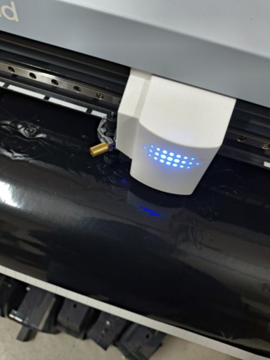
Pen force and origins were already configured. After loading the roll, the machine was ready and the file was sent to cut. Once finished, the piece was removed using a cutter.
The vinyl cutter in action, following the cut paths.
Video of the cutting process.
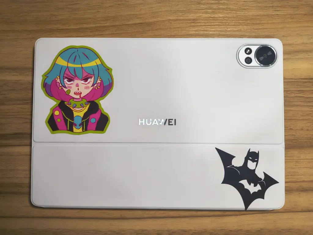
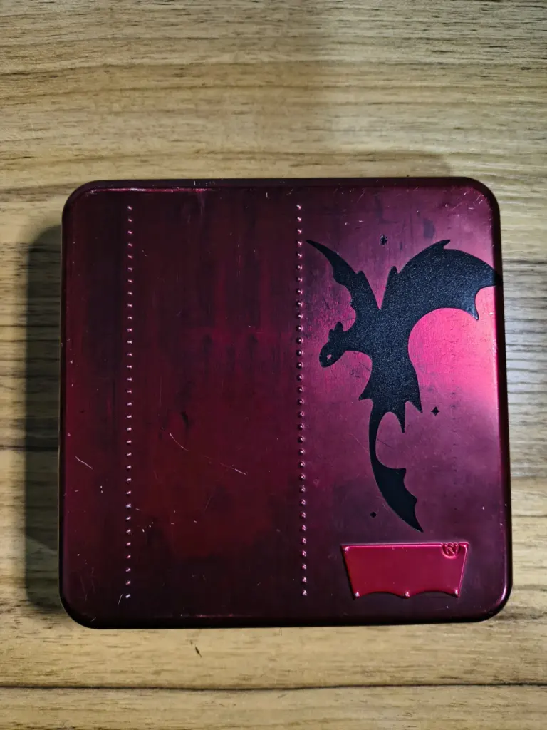
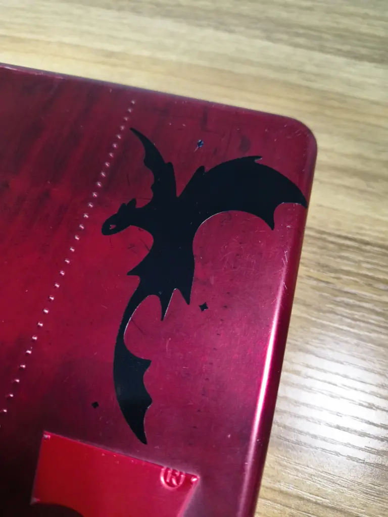
Weeding, Transfer & Final Application
After cutting, the excess vinyl must be removed (weeding). Then transfer paper is applied and the design is placed on the final surface.
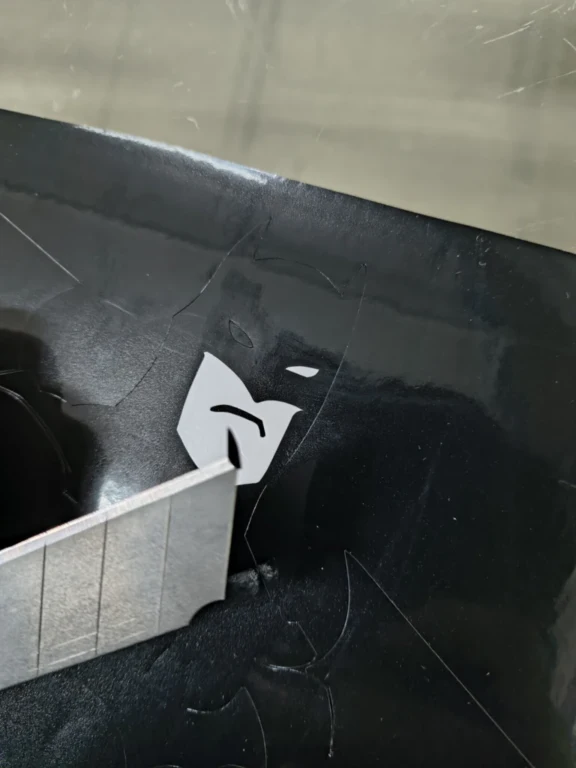
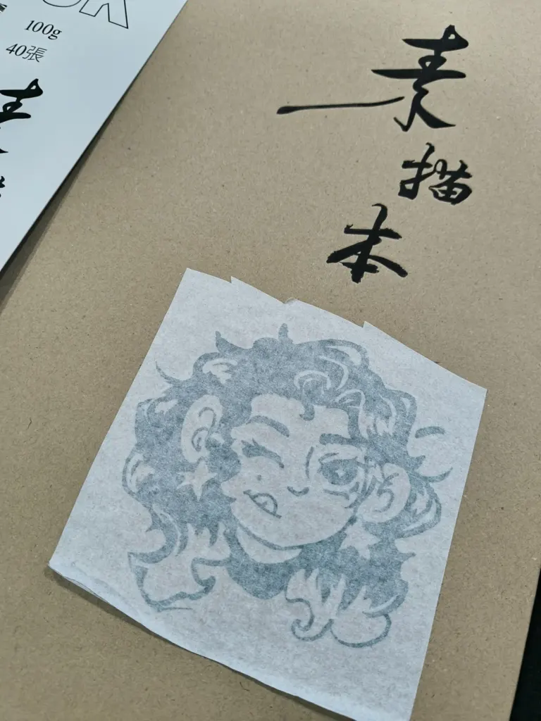
Weeding, removing excess vinyl using the tip of a cutter. Weeding tweezers or hooks work better for detailed designs.
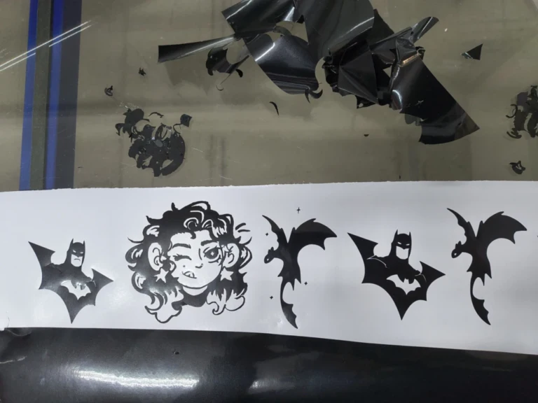
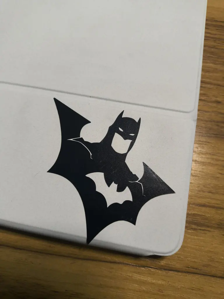
All designs weeded and ready for transfer paper.
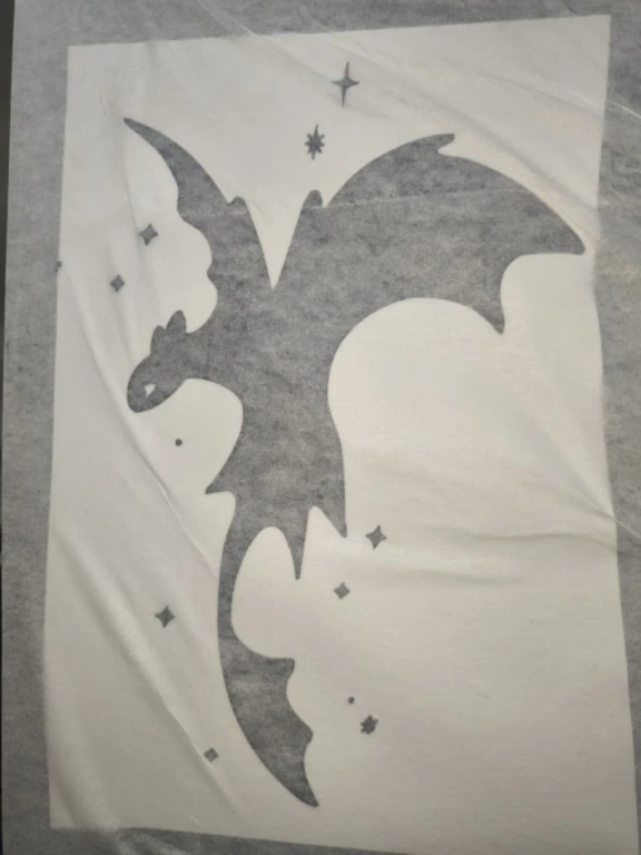
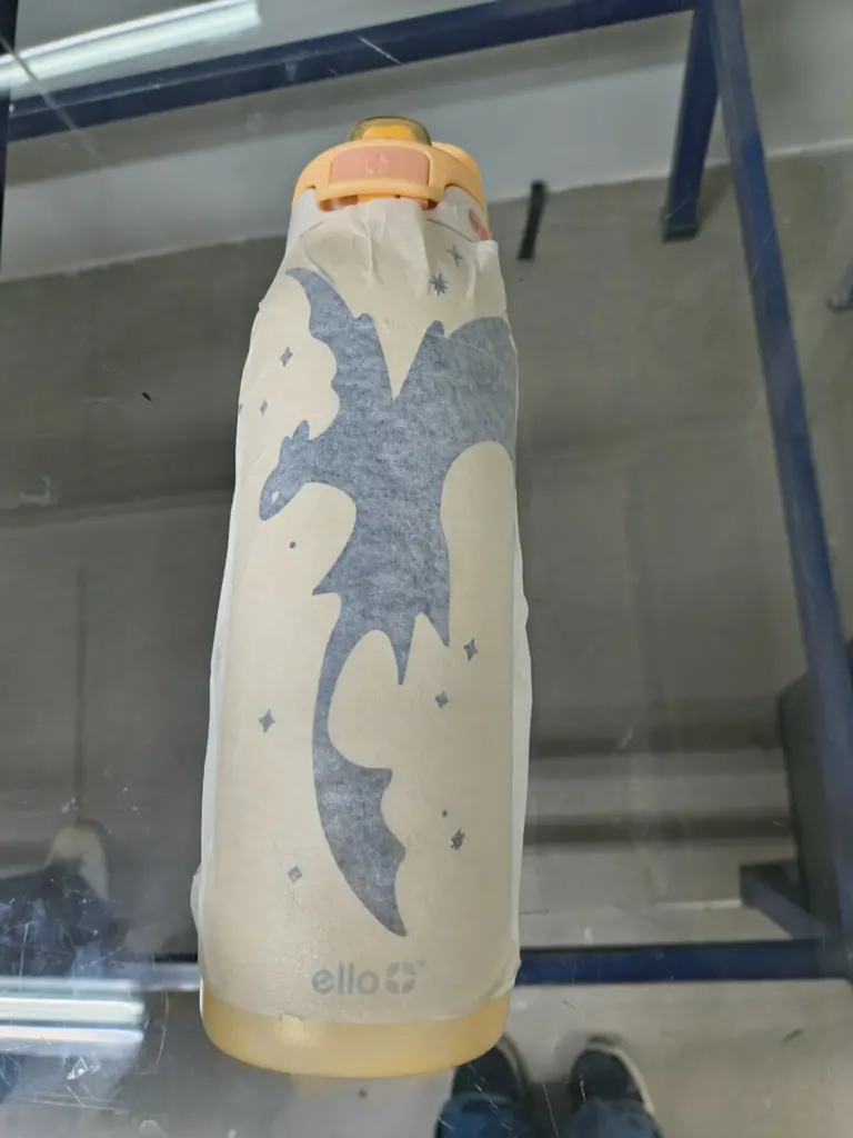
Transfer paper application , it works similarly to masking tape. Press with a card while rolling the paper evenly to avoid wrinkles.
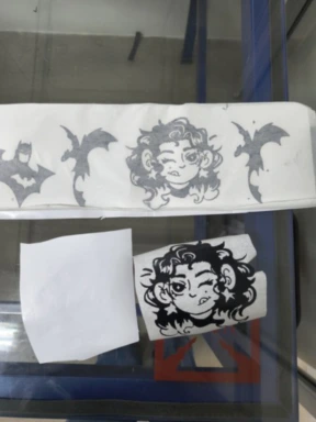
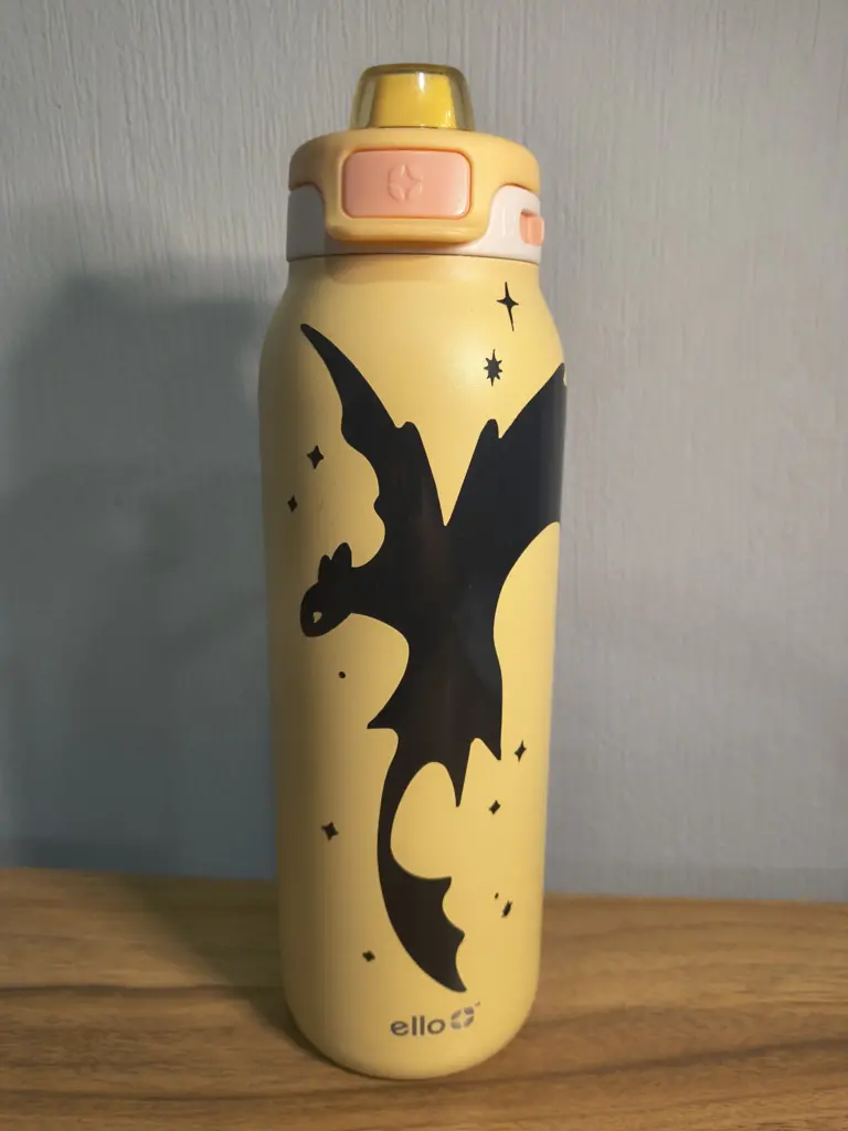
Final application , clean the surface, remove dust or grease, place the design, press with a card, and peel the transfer paper.
Learning Outcomes
This week strengthened my understanding of the relationship between digital precision and physical
material behavior.
Kerf is measurable, not hypothetical:
Before this week, I only considered "small tolerances" without actually measuring kerf.
Learning how to calculate it precisely changed my approach to joint design and assembly accuracy.
Laser parameters directly affect quality:
If parameters are not calibrated correctly, the machine may not cut through the material or may
burn it excessively. Testing speed and power combinations is essential for clean results.
Lab safety training is essential:
The laser cutter requires strict safety protocols. I learned about ventilation systems, fire risks,
material restrictions, and the importance of never leaving the machine unattended.
Understanding which materials are safe to cut and which release toxic fumes is critical.
Material behavior matters:
Warped material, thickness variations, and incorrect focus can compromise the final piece.
Not all errors come from the design , some may come from setup conditions.
2D design for fabrication:
I also learned that 2D design can make 3D objects , for example the flex hinge pattern, where
distances and design directly affect bending angles and results.
Vinyl cutting as a complementary process:
The vinyl cutter follows a similar CNC logic to laser cutting.
It can be used to customize and finish projects, adding an extra layer of detail.
I will apply this knowledge in future projects that require press-fit systems or modular assemblies.
Measuring kerf instead of guessing tolerances will now be part of my workflow for laser cutting.