
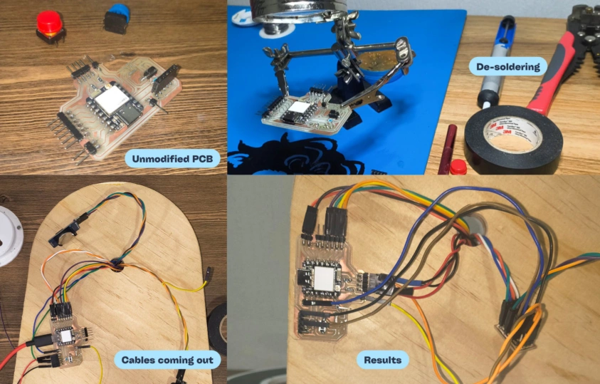
Can the gear and carousel move one compartment reliably with 512 steps?
No. In the final calibration, one compartment needed around 1030 steps to align correctly and dispense reliably.
✦ María José Ballesteros Andraka ✦
This project originates from a previous version I made in high school for my grandfather, who takes the same medications every day. However sometimes he forgets to take them, and most of the time only my mother or his caregivers know exactly which pills he needs and whether he has already taken them.
Sometimes other family members and I help refill his medication, but we don't always know his exact routine. Even if the medicine is the same (it might vary depending on the doctor's future prescriptions), its appearance can vary between pharmacies, so it's hard to tell doses apart just by how they look.
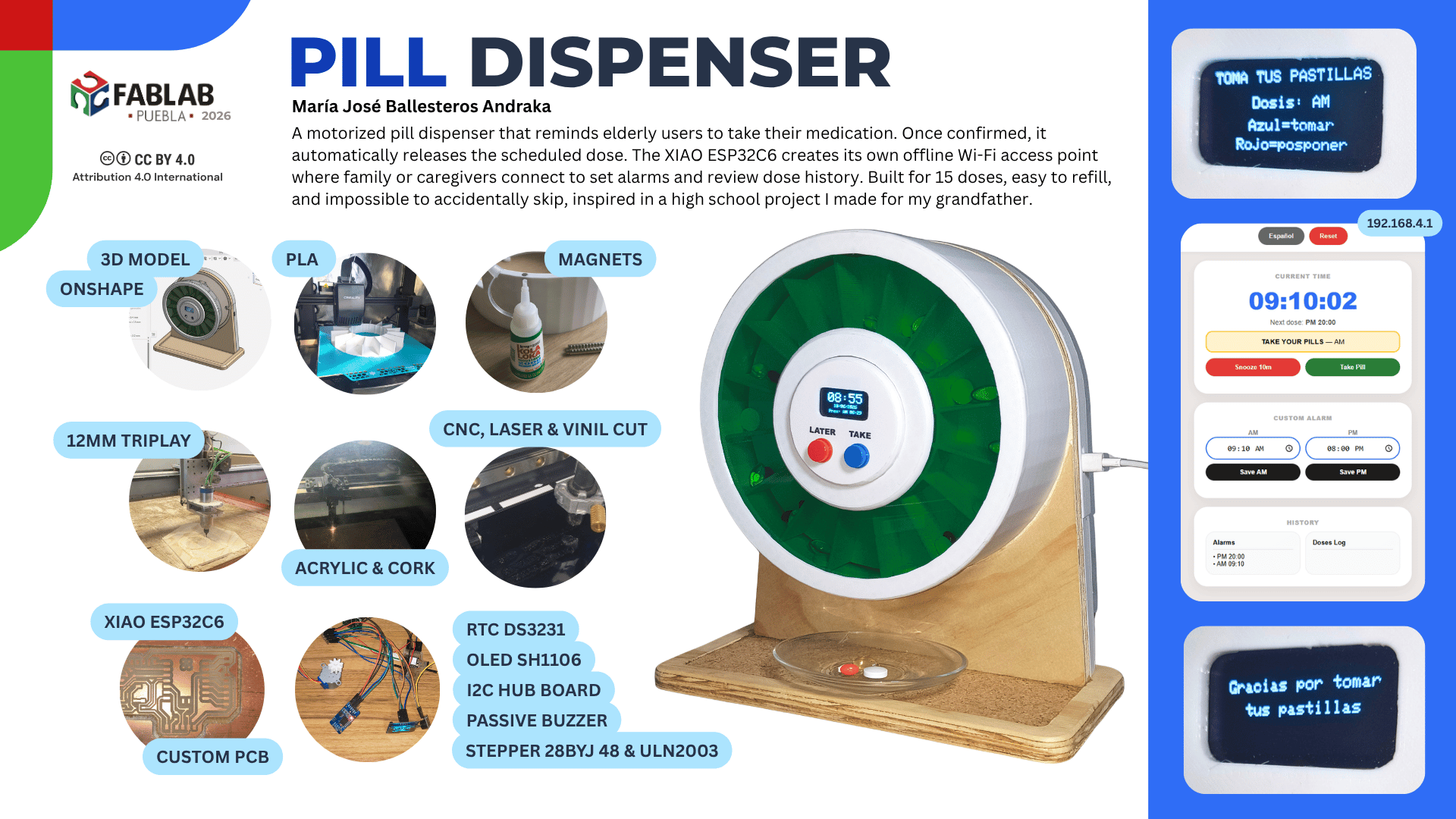
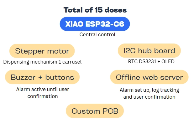
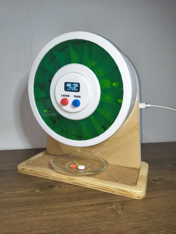
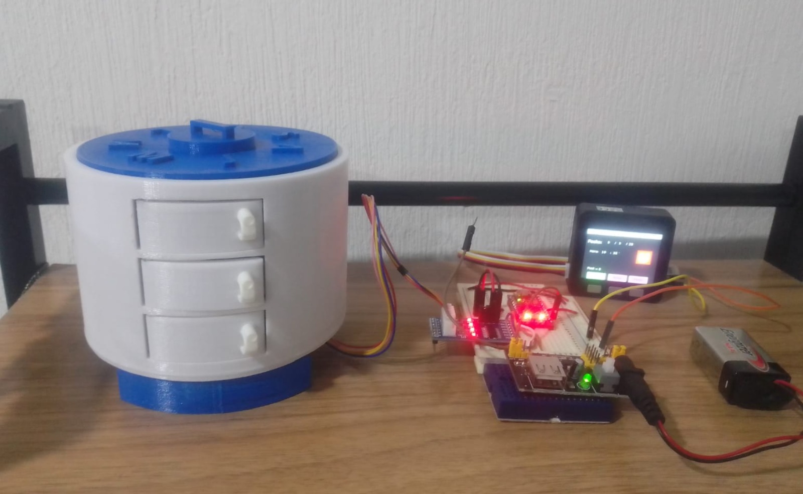
This is why I decided to make a smart pill dispenser for my final project. The concept changed through the weeks but at the end resulted in a motorized dispenser that can hold up to 15 single doses. The device doesn't dispense automatically on purpose to avoid dispensing without the user's knowledge. So when the RTC reaches a programmed alarm time, the buzzer keeps the reminder active until the user either confirms the dose or postpones it. After confirmation, a 28BYJ-48 stepper motor advances the carousel to release the scheduled medication. Dispensing occurs thanks to gravity when a compartment aligns with the opening.
The project is powered by a XIAO ESP32 that controls the mechanism, synchronizes the OLED display, reads the buttons, and hosts its own WiFi Access Point where family members or caregivers can connect to set the alarms and check dose logs. The enclosure is made of 3D printed PLA parts, a laser cut acrylic cover, and CNC routed plywood.
At this stage I was still exploring different ideas. I wanted something meaningful, functional, and connected either to a real problem or to a personal interest.
Before choosing the final project I compared three other directions. Each one had a different focus: mobility, sustainability, or health care.
In high school, I designed a first prototype for a week of medication with three pill schedules per day. It worked as a concept, but it was not very useful in practice.
The first idea was to make a 31-day dispenser so the family or caregivers could fill it once a month and not worry about refilling it every week. It was divided in four sections (one for each week) and each section had enough space for the pills.
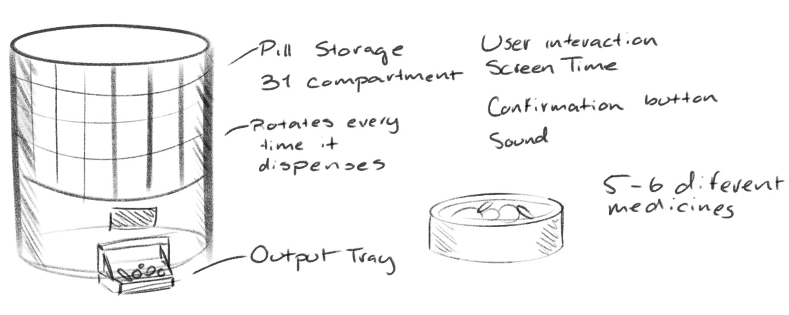
One challenge of this concept is that I wanted to cover different scenarios and user needs, like separate AM and PM dosing. Meaning that there should be at least 62 compartments, which would make the device bigger and more complex.
During week 02 I explored the sketch shape in two different 3D modeling software programs: Inventor and Onshape. While Inventor allowed me to render the result, I'm more familiar with Onshape as I found it both easier and faster.
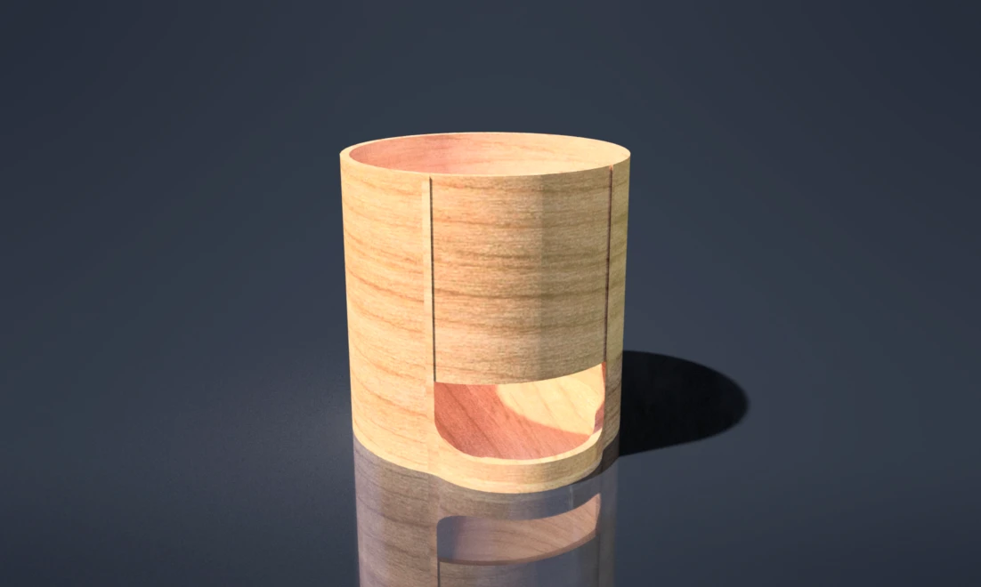
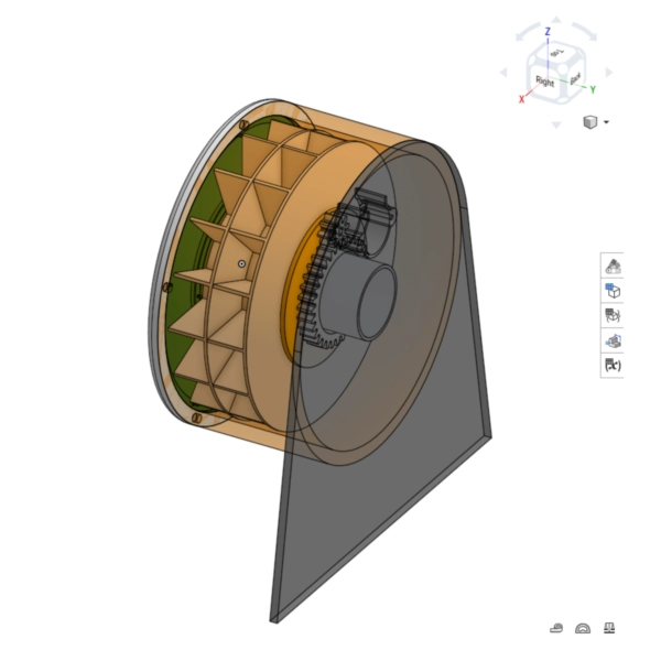
The first model was designed to have horizontal carousels that would be stacked above each other. However I later changed it to a vertical design, because the first version would require a more complex dispensing mechanism, while the vertical one could rely just on gravity to drop the pills.
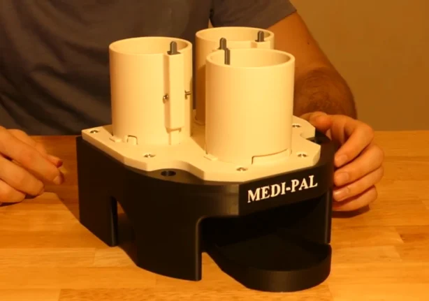
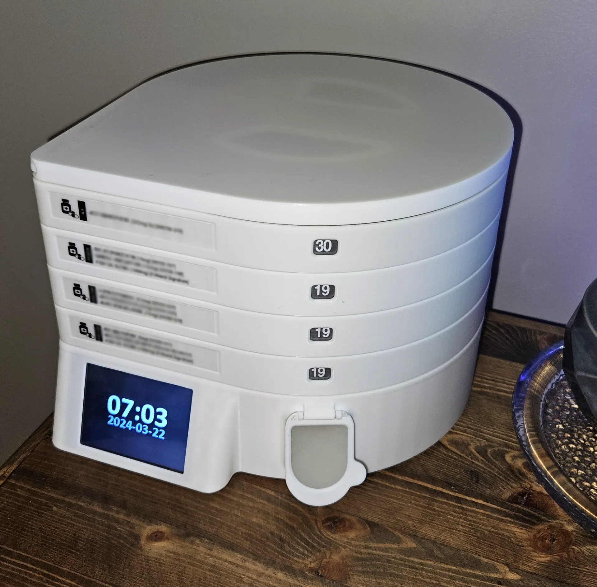
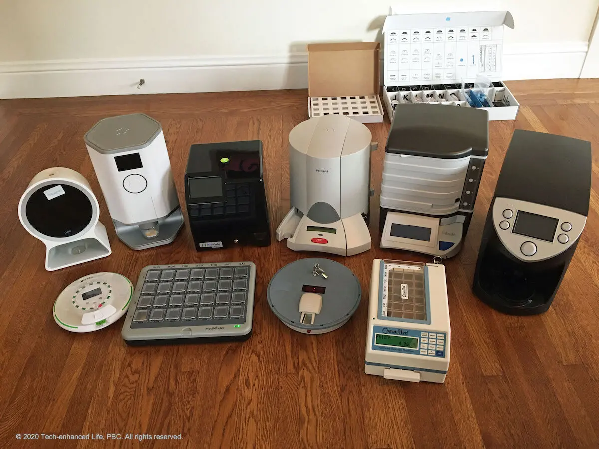
While figuring out how the device would work, I investigated analog cases and existing products in the market. Particularly, I liked the analysis made by "Tech-enhanced life" where they compared different devices and their approaches to pill dispensing and refilling.
I also liked the system developed by "Michael Sangiorgio" that consists of rotating cylinders for each pill type that rotate and dispense just one pill. Lastly the modular pill dispenser by "Shaztech" was a great reference of system integration and mechanism design.
However later on I discovered a manual pill dispenser from the brand "Zoksi" that dispenses the pills when the user presses a button and the pills fall by gravity, rescuing the idea of vertical carousels.
After exploring the first concept and looking for inspiration, I made a second round of sketches to explore different shapes. I wanted to keep the idea of a monthly dispenser easy to use. So I ended up with a vertical design that relies on gravity for pill dispensing with two carousels.
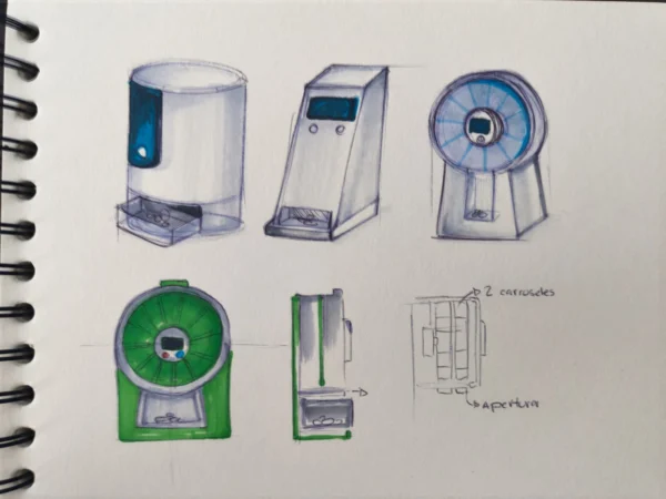
Later on while modeling, the idea was reduced to a single vertical carousel. However in the future I would like to make a monthly version with multiple doses.
The first schedule I did only covered the early planning stages. However, in reality, the project was defined progressively through the Fab Academy assignments, and started taking shape around Week 11 when the local WiFi interface became part of the system. Even when I made a schedule I had some setbacks and changes in the project scope, so at the end some things happened in a different order than planned.
| Week | Dates | Project contribution | Status |
|---|---|---|---|
| Week 01 and 02 | Jan 21 to Feb 3, 2026 | Explored possible directions and started the website. Then modeled the first CAD version of the dispenser | Completed |
| Week 04 | Feb 11 to Feb 17, 2026 | Introduction to embedded programming, did an alarm exercise in wokwi (servo motor, stepper, rtc, lcd, led , buzzer and buttons) | Completed |
| Week 06, 08 and 10 | Feb 25 to Mar 31, 2026 | Introducction to electronics design and production. In week 6 I made my first PCB, on week 08 I produced a modular one that was improved on week 10 for the Outputs exercise taking in consideration the project needs. | Completed |
| Week 09 | Mar 18 to Mar 24, 2026 | Worked with real components and learned about the RTC DS3231 and I2C communication. | Completed |
| Week 10 | Mar 25 to Mar 31, 2026 | Integrated outputs such as buzzer and servo motor. | Completed |
| Week 11 | Apr 1 to Apr 7, 2026 | Defined the project more clearly, added and OLED connected to the RTC, created an access point and a web interface for alarm configuration. | Completed |
| Week 14 | Apr 22 to Apr 28, 2026 | Explored and improved the interface logic for configuring alarms, checking status, and making the dispenser usable by caregivers. | Completed |
| Week 15 | Apr 29 to May 5, 2026 | Redifined the project system integration, started doing the final CAD design. | Completed |
| Week 16 | May 6 to May 12, 2026 | Continued physical production, 3D printing and corrections. | Completed |
| Week 17 | May 13 to May 19, 2026 | Defined the project applications and implications, that include bill of materials, future improvements, and questions required for final evaluation. | Completed |
| Week 18 | May 20 to May 26, 2026 | Defined how the project could be shared. Assembly and integration of all components. | Completed |
| Final preparation | May 27 to Jun 10, 2026 | Finished the working prototype, code corrections and the final video/slide for presentation. | Ready |
| Presentation | Jun 11, 2026 | Fab Academy final project presentation. | Presented |
| Local corrections | Jun 11 to Jun 24, 2026 | Clarified documentation, added evidence, and adjusted content with local evaluator feedback. | Review |
| Global corrections | Jun 24 to Jul 1, 2026 | Final page polish and corrections for global evaluation. | Review |
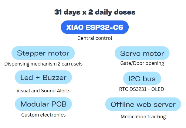
The first system diagram was designed for a more complex version of the dispenser with multiple carousels for 31 days of medication. The main components include an RTC, OLED, buzzer, stepper motor, and a servo that would move a door/gate to release the pills.
However for the final version, the system was simplified to a single carousel with a stepper motor and a gravity-based dispensing mechanism, eliminating the need for a servo. Here the doses per day vary depending on the user: it can work for one dose every 15 days or two doses per day for a week, depending on the user's needs.
When I started modeling the final concept of the dispenser, I wanted to keep the idea of a monthly dispenser even if it was just one dose (two doses monthly would require 62 pill sections). That is why I made two carousels with 16 divisions (15 doses, as one section is the opening).
However, I realized that the 31-day approach would make the device bigger and I couldn't visualize where to put the components, such as the servo motor controlling the sliding gate to prevent the pills from both carousels from falling at the same time. This resulted in the following version:
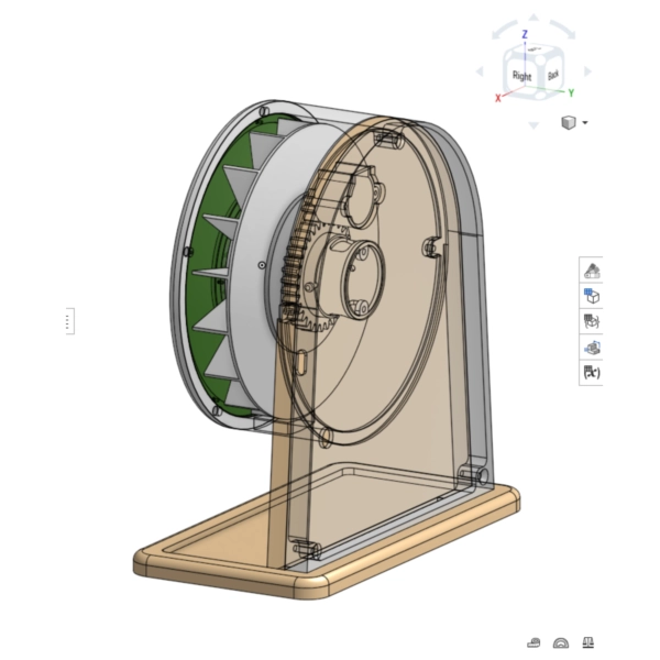
I used Onshape for the 3D modeling. First I defined the global measures to make the design parametric, then I created the sketch for each part and extruded them. All of the parts were modeled together to make sure they fit and the assembly process was clear. As I was finishing the model, I 3D printed some parts to test the mechanism and make sure the tolerances were correct.
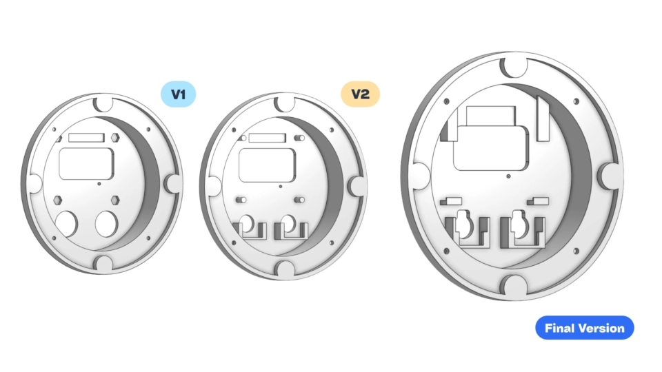
Some of the pieces required adjustments after testing, so I went back to the model to make the necessary changes and then printed the final version of each part. One example of this is the center piece where the OLED and buttons are, the first version used nuts to secure the OLED, however I didn't have the heat seat inserts so they moved, so I redesigned it to have a snap fit to secure the elements.
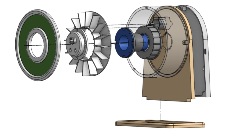
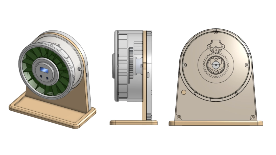
In total, the CAD model consisted of 14 pieces. Here I already considered which pieces would be 3D printed, which ones would be laser cut (green acrylic), and which ones would be CNC routed (plywood). I also made sure to design the pieces in a way that they could be easily assembled and disassembled.
To download the 3D models of the dispenser, click on the image below. The files are in STL format and can be used for 3D printing. The files are organized with the part number, name, and the material used to fabricate them.
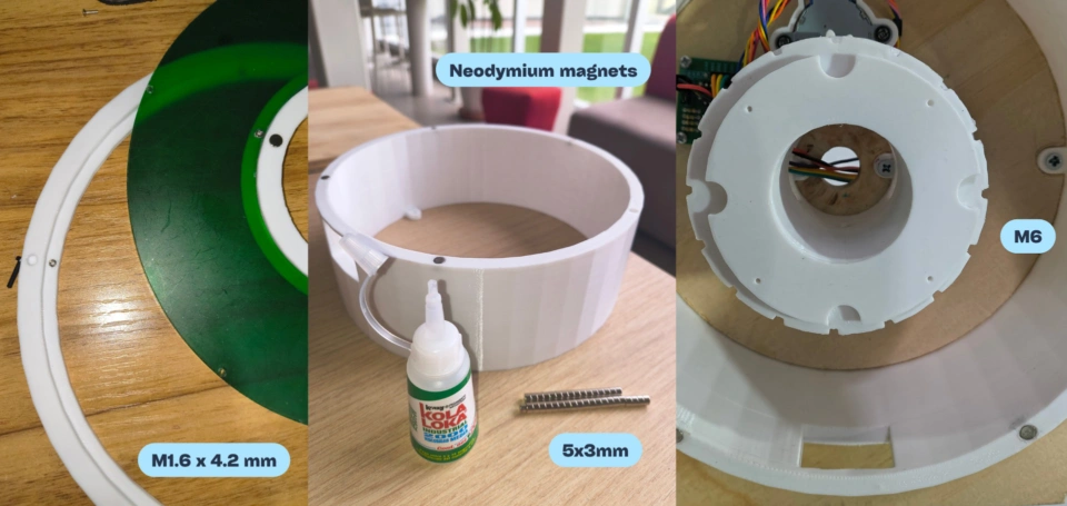
Please note that the tolerances may require adjustments for your specific 3D printer or material. Normally I use a 0.2 mm tolerance, however the magnets didn't fit so I ended up using 0.4 mm tolerance and it worked just fine. The magnets used were 5 x 3 mm. I also used specific screw sizes: M1.6 screws for the very small acrylic and OLED center piece details, and different M6 screw lengths for the parts attached to the wooden base. To know all the materials used, check the BOM table at the end.
To print the parts I used Creality Print Slicer and the Ender 3 V3 SE printer. I separated the parts in different print jobs to optimize the printing time and material usage. I also used supports for some parts that had overhangs, and I made sure to orient the parts in a way that minimized the need for supports.
Aproximately 0.7 kg of PLA is needed to print all the parts, and the total printing time is around 35 hours, this time is for the final prototype without counting the filament I used for testing and reprinting some parts.
| Step | Item | Parameters |
|---|---|---|
| Temperature | Hotend | 210 °C |
| Temperature | Bed | 60 °C |
| Speed | First layer | 30 mm/s |
| Speed | Outer wall | 60 mm/s |
| Speed | Inner wall | 90 mm/s |
| Speed | Infill | 180 mm/s |
| Speed | Top surface and supports | 50 mm/s |
| Layers and walls | Layer height | 0.16 mm |
| Layers and walls | Walls | 2 |
| Layers and walls | Infill | 10% |
| Layers and walls | Infill pattern | Gyroid |
| Cooling | Fan | 0% first layer, 100% after |
| Supports | Z distance | 0.2 mm top and bottom |
| Supports | Interface | 2 layers, 0.5 mm spacing |
| Supports | Object clearance | 0.35 mm XY, 0.2 mm first layer gap |
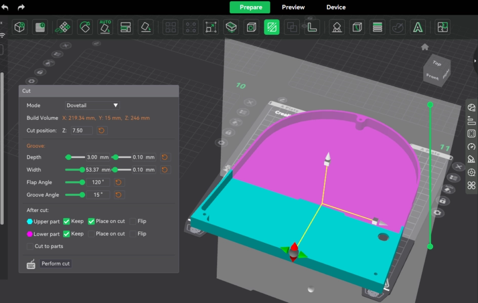
The only piece that didn't fit in the bed was the electronic enclosure, so I had to print it in two parts. On a bigger printer it could be printed in one piece. In the future I would like to make a version that could be printed in one piece on a smaller printer, or design a version that could be printed in two parts and assembled with screws or snap fits.
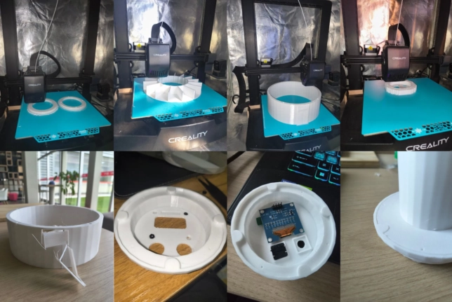
These are some photos of the 3D printed parts of the dispenser. After the printing job was done I waited about 10 minutes for the parts to cool down to removed them from the bed and prevent warping. Then I removed the supports with diagonal cutting pliers and cleaned the parts with a cutter knife.
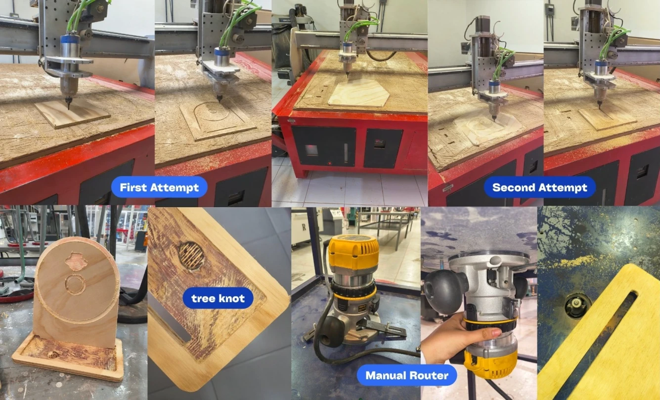
To route the plywood for the base, I downloaded the DXF files from Onshape. Then I opened them in VCarve to create the toolpaths (cutting and pocketing) for the CNC machine. At first I used the parameters I had used on Week 07, however I had to adjust the feed rate and spindle speed to get a better finish on the plywood, as the circles looked more like ellipses.
At the end I made minor changes to the design, however because I already had the parts cut, I had to make those changes with a Dremel and drill. The changes include a 20 mm hole for the cables to pass through. Here are the updated DXF files.
For the new toolpaths I used 10,000 RPM spindle speed and 900 mm/min plunge rate. Then the contour was cut at 2,500 mm/min, with 4 mm per pass, and 3 passes. The pocket was cut slower, at 1,500 mm/min, with 3 mm depth in one pass. The slower pocket speed helped improve precision on the curved geometry.
After CNC routing, I sanded the plywood with 220-grit sandpaper to remove any rough edges. I also used the manual router with a 1/8" roundover bit in the base.
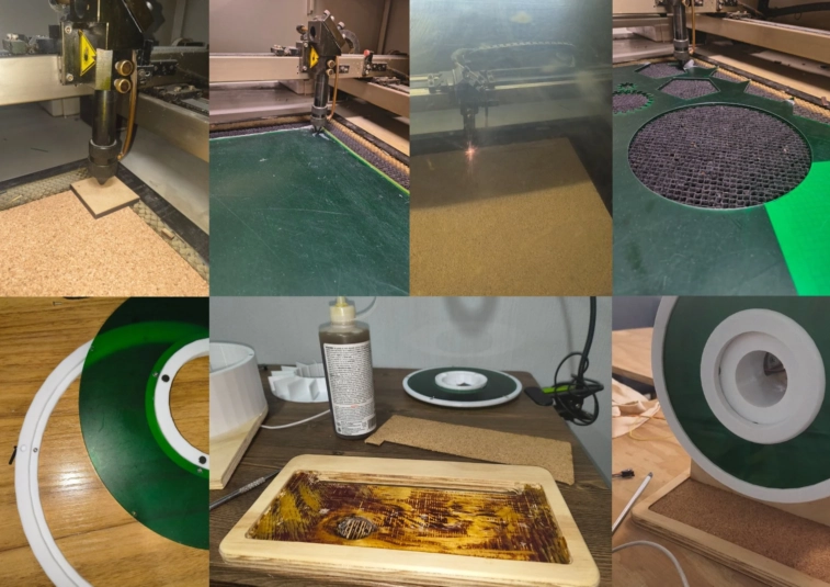
When the router made the pockets, a tree knot in the plywood was exposed, so I decided to laser cut a piece of cork to cover it. I also laser cut the acrylic for the dispenser cover. Here are the DXF files. The parameters used were:
| Material | Max power | Min power | Speed |
|---|---|---|---|
| Cork | 35% | 25% | 30 mm/s |
| Acrylic | 70% | 60% | 25 mm/s |
The cork was used to cover the exposed plywood knot, while the acrylic piece became the removable transparent cover for refilling the dispenser.
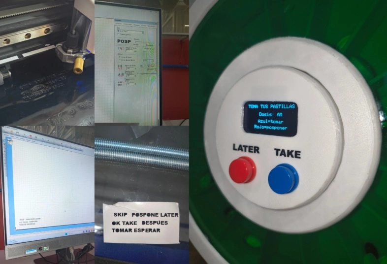
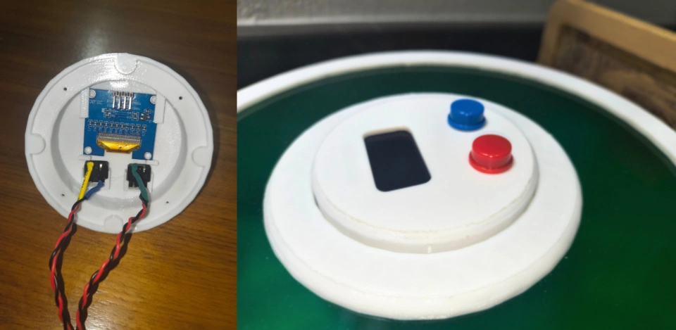
I added vinyl labels to the buttons because, even though the OLED display explains what each button does, I thought it was better to have a clear visual reference directly on the enclosure. At first I considered making the labels in Spanish, but I chose English because the words were shorter, simpler, and clearer. This allowed me to keep a readable text size, if the letters were smaller they would have been harder to read and also more difficult to weed from the vinyl.
I followed the same vinyl cutting process from Week 03. For the final labels, I added the text directly in the cutting program using the VersaSTUDIO GS2-24 from Roland and the CutStudio software. I used Arial Black with a height of 3 mm, then cut, weeded, and transferred the labels onto the prototype.
The electronic part of the project changed a lot through the Fab Academy weeks. My first approach was a Wokwi simulation to test an alarm logic, then I learned the basics about PCB design (I built 3 different ones, the first to learn, the second with more intention and the third one for testing/final project). With the board ready, I learned about the RTC and I2C communication, then I integrated some outputs (buzzer and stepper motor) and finally I created a local web interface to configure the alarms and check the status of the dispenser.
My first version of the project was a Wokwi alarm exercise. Here I simulated an alarm that when triggered, would activate a buzzer (that played the Imperial March song), both a servo and a stepper motor. While displaying the time (of the RTC) on an LCD. To configure the alarm, I used 3 buttons. This exercise introduced me to the basics of programming, and how to use the Wokwi simulator to test my code and electronics before moving into real components.
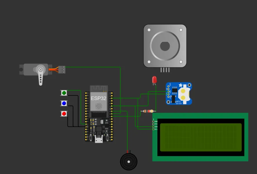
This was the final result of this exercise. Please note that I used ChatGPT as a support tool during the coding process. It helped me choose suitable ESP32 GPIO pins, generate the alarm melody frequencies, and debug errors when the code did not behave as expected. I used its suggestions to better understand the logic and then adapt the code to my project.
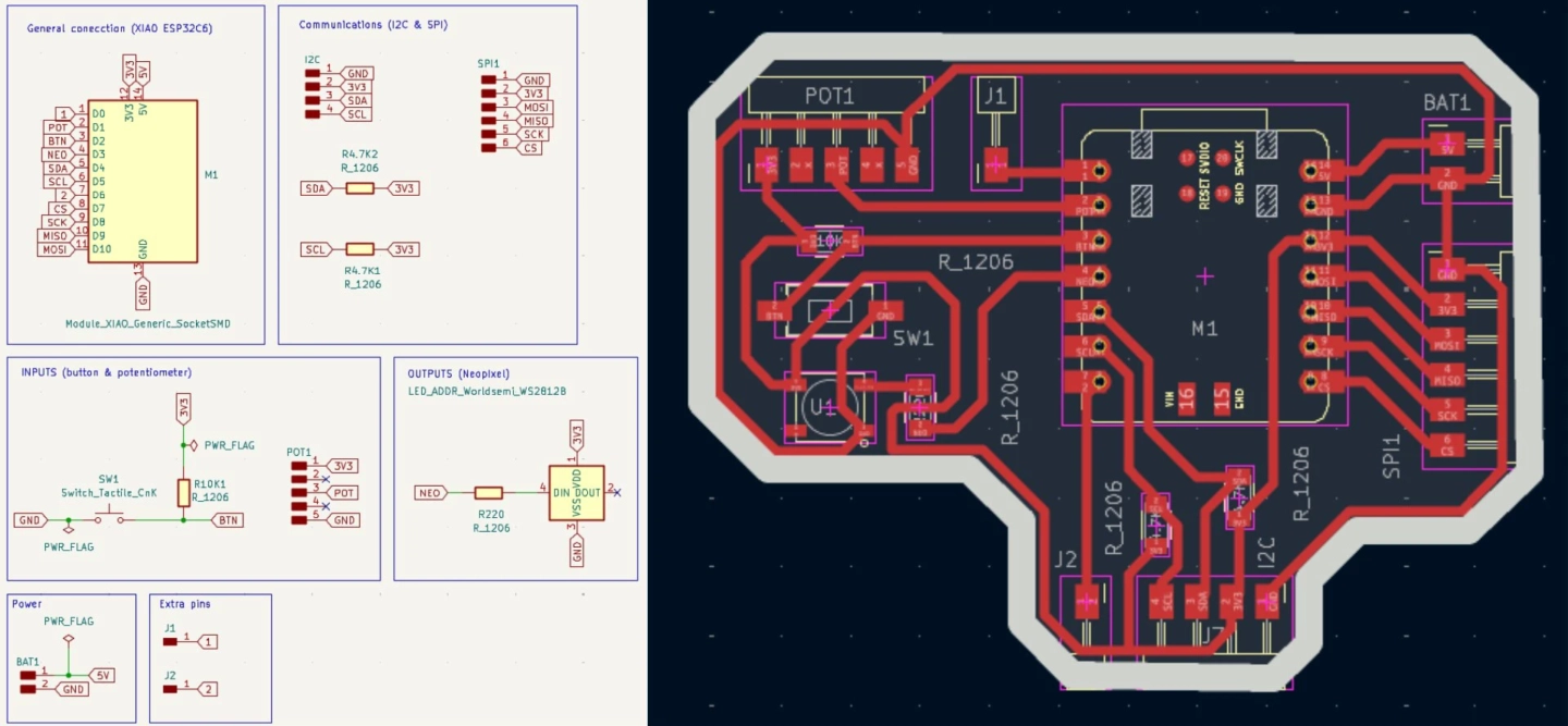
On week 06 I learned how to build a schematic from components in KiCad. This first board taught me how to organize signals before moving into physical routing. There are several improvements that could be made to this board, specially space and routing, but it was a good first experience to understand the workflow of PCB design.
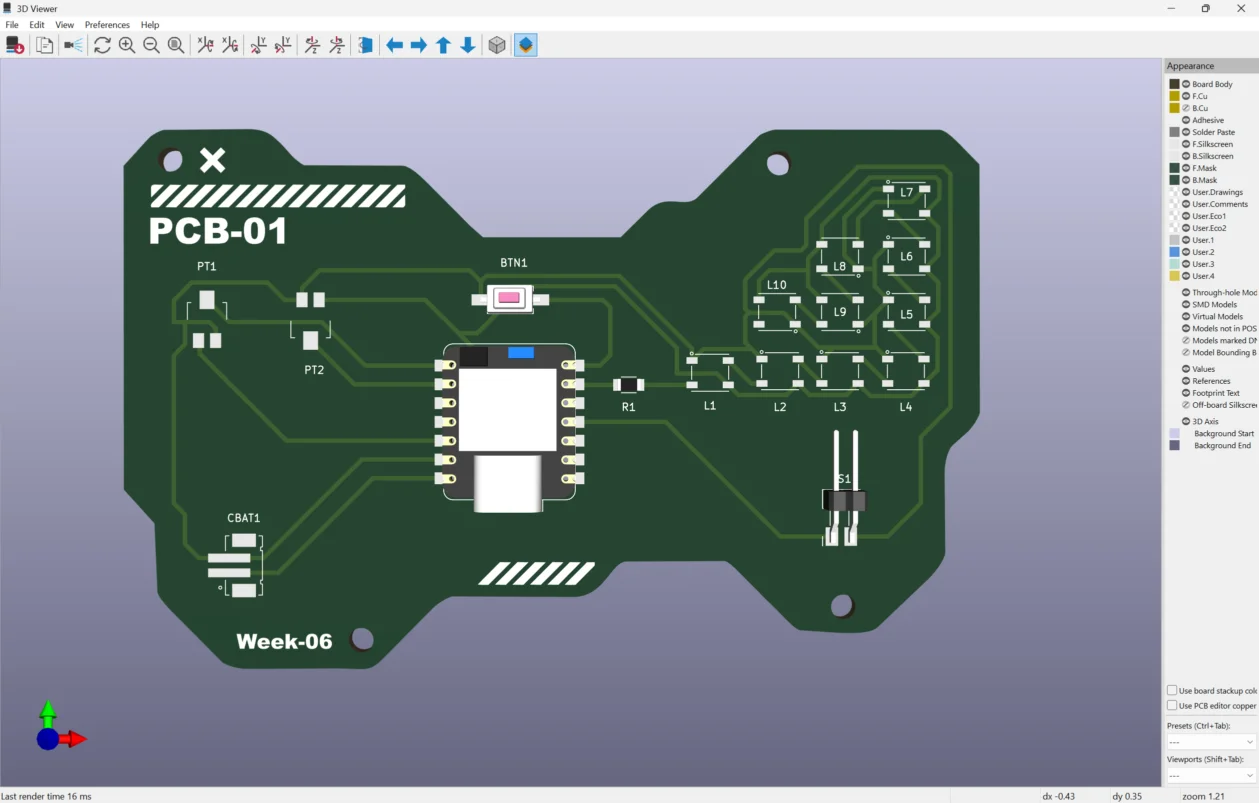
During week 08 I fabricated and soldered my first board. For this I designed a new PCB for testing, which is why I included three NeoPixels and a button. I also experimented with pin headers dedicated to two potentiometers. Overall this week gave me the practical workflow for Gerbers, milling, cleaning traces, placing components, soldering, and debugging fabrication mistakes.
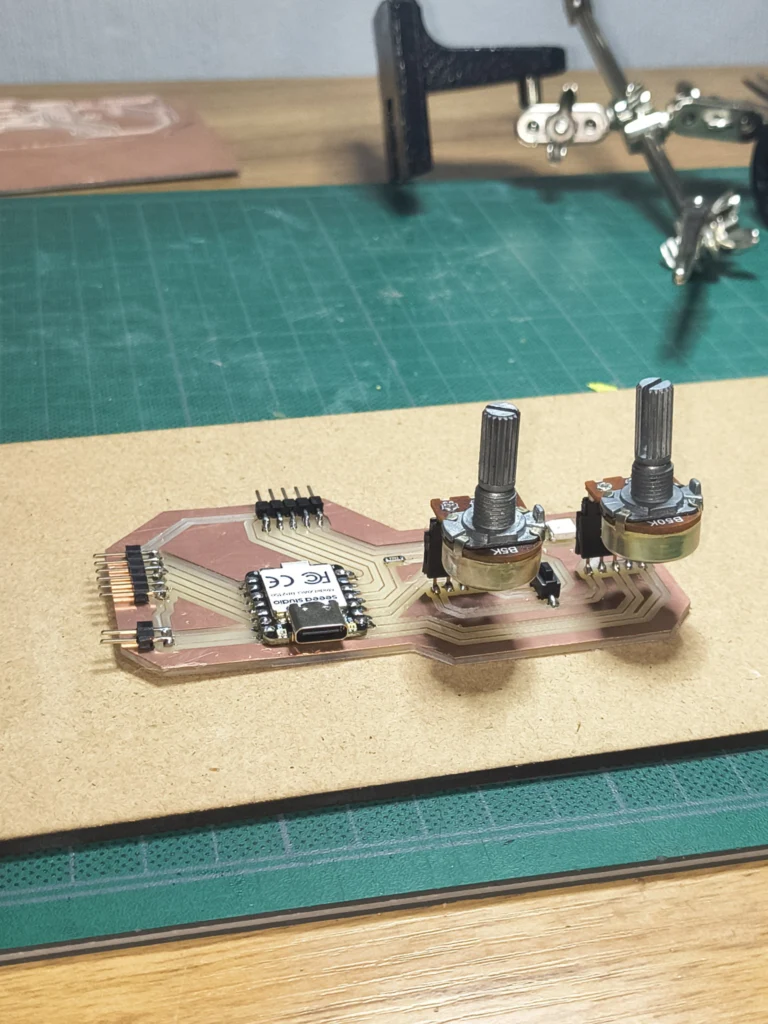
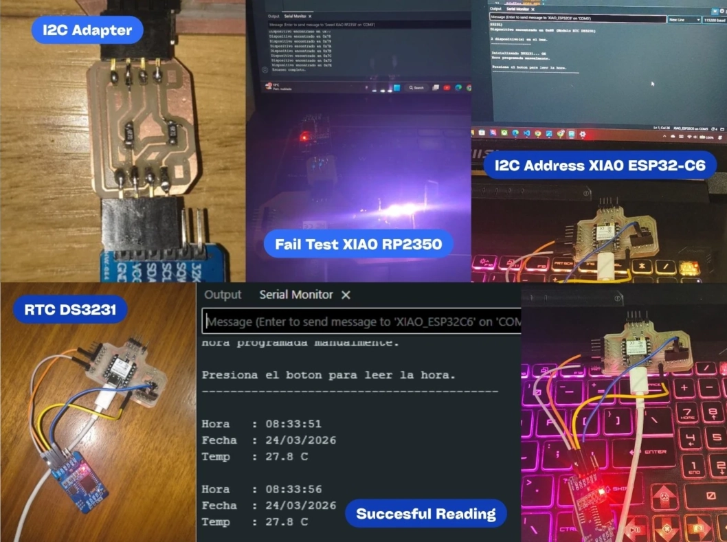
During week 09 I tried to do I2C communication with the board made on week 08 that used a XIAO RP2350. But I wasn't successful, so I repeated the whole PCB during week 10 with a XIAO ESP32-C6 designed to be adaptable for future assignments like Networking but also for the final project.
I repeated the PCB because I couldn't find the root of the problem. The serial monitor showed multiple addresses for the I2C bus, and I couldn't determine whether it was the code, a physical connection, or the PCB soldering. However some of my classmates also encountered some problems while working with the RP2350.
At first, I designed an I2C adapter because my PCB didn't include the pull-up resistors needed for reliable communication. The first tests failed and showed inconsistent addresses. After redesigning the PCB, the RTC worked correctly without the adapter. I also discovered that, on my XIAO ESP32-C6 setup, the I2C bus worked on D0 and D1 instead of the default pins (D4 and D5).
Thanks to the Outputs group assignment I learned about the power consumption of several components including a servo, a passive buzzer and an OLED display.
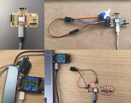
The programmed result was an alert sound followed by a controlled mechanical movement. When the button was pressed, the buzzer played the alarm melody and the servo moved from 0° to 90° before returning to its original position. This test helped me simulate the basic interaction of the dispenser.
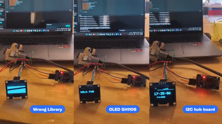
For Networking & Communication I made an I2C hub board where both the OLED and RTC would be connected. While programming I encountered the problem that the display didn't show the time, just some noise. This was because I was using the wrong OLED library. When I changed it to the correct library for the SH1106, it showed the message from the code (Hello Fab!). Afterwards, it was programmed to display the time set by the RTC.
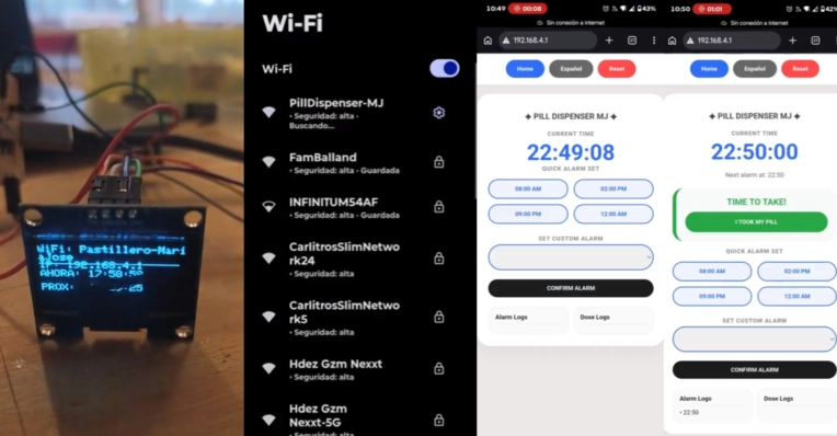
After the RTC and OLED were working, I added the web server. The XIAO ESP32-C6 creates its own WiFi Access Point, PillDispenser-MJ, so a phone or computer can connect directly without internet. Then the browser opens the local interface at 192.168.4.1.
The interface lets the user set an alarm, confirm that the dose was taken, switch language, reset the system, and view recent alarm/dose logs. On startup, the OLED shows the network name and IP address for a short connection window, then returns to the clock display.
In Week 14 I explored a different interface approach using Qt Designer and Python. Instead of only using the ESP32 web page, I designed a desktop interface where a caregiver could select the port, set an alarm time, choose active days, and send commands to the XIAO ESP32-C6 through Serial communication.
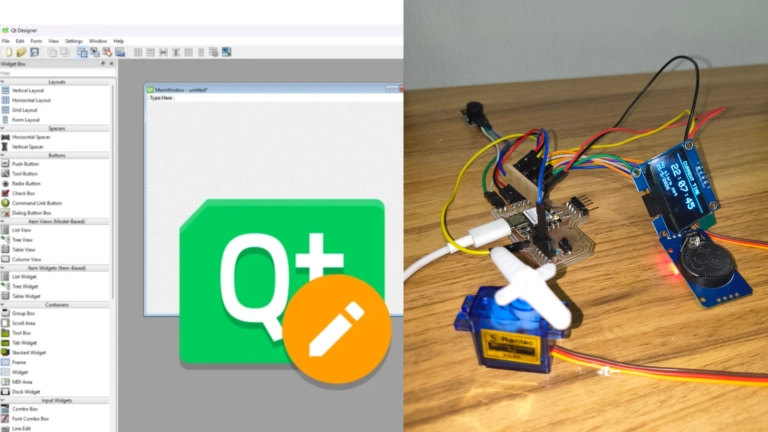
The Python app and the firmware exchanged simple text messages. Python sent commands like SET_ALARM,HH:MM,DDDDDDD and PILL_TAKEN, while the XIAO responded with messages such as ALARM_TRIGGERED and PILL_CONFIRMED. This helped me test alarm configuration, confirmation, and status feedback before integrating everything into the final dispenser. However for me this approach was more complicated and the ESP32 needed to be connected to the computer.
The complete Wokwi sketch is documented in Week 04. It includes the RTC, LCD, buttons, buzzer melody, LED, servo, and stepper logic used in the first simulated alarm version.
//Include is used to call libraries with either #include or "name"
//They allow us to use pre-written functions
#include // it allow us to communicate with the screen and time module
#include // to control the LCD screen
#include // To control the real time module (in this case DS1307)
#include // to control the servo
//Configuration
LiquidCrystal_I2C lcd(0x27, 20, 4); //(Address LCD, columns of the screen, rows on screen)
RTC_DS1307 rtc; //no need of parenthesis the I2C address is fixed internally
Servo ServoCross; // Creates a servo object (I name it cross because I changed the horn to be a cross)
//The pin of each component, I asked ChatGPT which connections were better for each one
//The const int (constat integer) is to define a value that cant change later on
const int pinServo = 18; // Pin type Output PWM capable (Pulse width modulation)
const int pinBuzzer = 19; //Output (PWD)
const int pinLED = 5; //Output
//Inputs (when we press the button the ESP32 reads the signal either LOW or HIGH)
const int btnConf = 27; //Changes if we are introducing the hours (H) or minutes (M) or if its on standby
const int btnUp = 14; // The numbers go up
const int btnDown = 12; // The numbers go down
//Control pins for the bipolar stepper motor
const int stepPin = 32; // Controls the steps by reading the pulses HIGH and LOW (each pulse is one step)
const int dirPin = 33; // Controls direction (HIGH is clockwise while LOW is the opposite)
// Star Wars Imperial Song for the alarm
int melodia[] = { // Int for whole numbers without decimals can be positive or negative
440, 440, 440, //Number of Hertz; I asked ChatGPT for the Hz equivalent of the notes similar to the imperial march song
349, 523, 440,
349, 523, 440,
659, 659, 659,
698, 523, 415, 349
};
int duraciones[] = {
75, 75, 75, // reduced duration for faster melody
50, 25, 100,
50, 25, 125,
75, 75, 75,
50, 40, 75, 125 // The number of durations are the same as the number of notes we have
};
const int totalNotas = 16; //Total of notes
// Melody variables, without them we wouldn't know the next note or the program would read the same note
int notaActual = 0; // The note that is currently playing
unsigned long tiempoNota = 0; // The time the note started, unsigned long is use for positive whole numbers
// Clock and alarm variables
int alarmaHora = 0; //Hour
int alarmaMinuto = 0; //Minute
bool editandoAlarma = false; //Bool means true or false, true if edits the alarm
bool editandoHora = true; // True if we are editing the hour, false if it is the minute
bool sonando = false; // true when the alarm activates
bool showThatsAll = false; // true to display "that's all for now" after stopping
unsigned long debounceTiempo = 0; //Prevents button bouncing (false/multiple triggering)
// Servo variables
int posServo = 0; //Position of the servo (angle from 0 to 180 degrees)
unsigned long tiempoServo = 0; //Timing of its movement
//Stepper variables
int pasosStepper = 0; // Counts how many steps it moves
bool dirStepper = true; //Direction of rotation
//Main difference between stepper (open loop) and servo (closed loop)
//function to reset the stepper
void resetStepper() {
pasosStepper = 0;
dirStepper = true;
}
//Set up function (runs once at the beginning, help us define the previous variables when the program starts)
void setup() {
Serial.begin(115200); // INICIA COMUNICACIÓN REMOTA SIMPLE
//pin mode help us define if the pins are inputs or outputs
pinMode(pinBuzzer, OUTPUT);
pinMode(pinLED, OUTPUT);
pinMode(stepPin, OUTPUT);
pinMode(dirPin, OUTPUT);
pinMode(btnConf, INPUT_PULLUP); //with the pull up the button pins have internal resistors
pinMode(btnUp, INPUT_PULLUP); //This way we wont need physical resistors
pinMode(btnDown, INPUT_PULLUP);
ServoCross.attach(pinServo); //attach the pin (in this case 18) to control a servo
ServoCross.write(0); // so it starts at 0 degrees
lcd.init(); //Initializes the LCD screen
lcd.backlight(); //Turn on LCD
rtc.begin(); //start the Rtc module
}
//Runs repeatedly forever
void loop() {
DateTime now = rtc.now(); //Current real time
manejarBotones(); // A function that check the buttons status
pantallaPrincipal(now); // the function that shows the hour
verificarAlarma(now);// to check if the alarm must sound
}
//Buttons
void manejarBotones() { //each if in here is a different task, independent from eachother
//When we use the buttons the program need to check several things at the same time
if (millis() - debounceTiempo < 30) return; // faster button change
// Edit or change mode of edition (editing alarm)
if (digitalRead(btnConf) == LOW) { //Conf button is the green one, when pressed is LOW
editandoAlarma = !editandoAlarma; //Changes between the alarm conf or standby
if (editandoAlarma) {
editandoHora = !editandoHora; //changes between changing the hour or the minutes in the alarm conf
}
debounceTiempo = millis();
}
if (editandoAlarma) { //Here we include the actions of the other buttons activated by editing the alarm
//Add numbers
if (digitalRead(btnUp) == LOW) { //button up is the blue one, if pressed is on low
if (editandoHora) {
alarmaHora = (alarmaHora + 1) % 24; //Adds one number and if we pass the 24 (hrs) resets to 0
} else {
alarmaMinuto = (alarmaMinuto + 1) % 60; //Same but for minutes
}
debounceTiempo = millis(); //Prevents bouncing
}
//Subtract numbers
if (digitalRead(btnDown) == LOW) { //red button
if (editandoHora) {
alarmaHora--;
if (alarmaHora < 0) alarmaHora = 23; //same but subtract one number at the time
} else {
alarmaMinuto--;
if (alarmaMinuto < 0) alarmaMinuto = 59;
}
debounceTiempo = millis();
}
}
}
// LCD Screen
void pantallaPrincipal(DateTime t) { //parameter that prints the rtc current time
lcd.setCursor(0, 0); //the starting point of the cursor
lcd.print("HORA: "); // Writes the word time on the lcd
imprimirDosDigitos(t.hour()); lcd.print(":"); //prints 2 digits of the time (hours)
imprimirDosDigitos(t.minute()); lcd.print(":"); //same but for minutes
imprimirDosDigitos(t.second()); //prints the seconds (real time)
lcd.setCursor(0, 1); // starts at the first column second row
lcd.print("ALARMA: "); //prints the word alarm
imprimirDosDigitos(alarmaHora);
lcd.print(":");//the word alarm is followed by the established one
imprimirDosDigitos(alarmaMinuto);
if (editandoAlarma) {
lcd.print(editandoHora ? " " : " "); // what it shows if we are editing the alarm
} else {
lcd.print(" "); //clear the extra part if not editing
}
lcd.setCursor(0, 3); //third row for alarm messages
if (sonando) {
lcd.print(" !Take your pills!"); // show alarm message
showThatsAll = true; // flag to show "that's all" after stop
} else if (showThatsAll) {
lcd.print(" That's all for now"); // show message after alarm stops
showThatsAll = false; // reset flag
} else {
lcd.print(" "); //clear row 3
}
}
// Alarm
void verificarAlarma(DateTime now) { //checks if the current times (DateTimeNow) matches the alarm
if (now.hour() == alarmaHora &&
now.minute() == alarmaMinuto &&
now.second() == 0) { //the exact second to start the alarm
//If the alarm is active (true)
sonando = true;
notaActual = 0; //it will start playing the melody on the first note
tiempoNota = millis(); // record the start time of the note
tone(pinBuzzer, melodia[0] / 4, duraciones[0] - 15); // starts the buzzer, divides the number to make the sound deeper
// remote communication
Serial.print("Alarma activada a las ");
Serial.print(alarmaHora);
Serial.print(":");
Serial.println(alarmaMinuto);
}
if (sonando) { //if the alarm is active
ejecutarAlarmaImperial(); //runs the melody we did before
if (digitalRead(btnConf) == LOW || //if any of the buttons is pressed the alarm goes off
digitalRead(btnUp) == LOW || // the two lines mean or, so if the blue button is pressed OR the green one it will stop
digitalRead(btnDown) == LOW) { // with out the two line we would lead to press the three buttons at the same time
detenerAlarma();
}
}
}
// Alarm song and led
void ejecutarAlarmaImperial() {
if (millis() - tiempoNota >= duraciones[notaActual]) {
notaActual++;
if (notaActual >= totalNotas) {
notaActual = 0;
}
tone(pinBuzzer, melodia[notaActual] / 2, duraciones[notaActual] - 25);
digitalWrite(pinLED, !digitalRead(pinLED)); //So the led follow the melody
tiempoNota = millis();
}
if (millis() - tiempoServo >= 100) { //moves the servo every 100ms
posServo += 20; // faster movement
if (posServo >= 180) posServo = 0;
ServoCross.write(posServo);
tiempoServo = millis();
}
digitalWrite(dirPin, dirStepper); //Moves the stepper step by step, changes direction after 100 steps
digitalWrite(stepPin, HIGH);
delayMicroseconds(400);
digitalWrite(stepPin, LOW);
delayMicroseconds(400);
pasosStepper++;
if (pasosStepper >= 100) {
dirStepper = !dirStepper;
pasosStepper = 0;
}
}
// Stop the alarm
void detenerAlarma() {
sonando = false; //stops the buzzer
noTone(pinBuzzer);
digitalWrite(pinLED, LOW); //turn off the led
ServoCross.write(0); //resets the servo
notaActual = 0; //resents the melody
resetStepper(); //resets the stepper
//Remote communication
Serial.println("Alarma detenida, gracias por tomar tu medicamento!");
}
//Format
void imprimirDosDigitos(int numero) {
if (numero < 10) lcd.print('0'); // makes numbers smaller than 10, two digit numbers by adding a cero at the start
lcd.print(numero);
}
This is the alarm-checking part of the Wokwi code. It compares the RTC time with the programmed alarm, starts the melody, and keeps the alarm behavior running.
void verificarAlarma(DateTime now) {
if (now.hour() == alarmaHora &&
now.minute() == alarmaMinuto &&
now.second() == 0) {
sonando = true;
notaActual = 0;
tone(pinBuzzer, melodia[0] / 4, duraciones[0] - 15);
Serial.println("Alarma activada");
}
if (sonando) {
ejecutarAlarmaImperial();
}
}
This is the complete Week 09 Arduino file for the DS3231 RTC and I2C test. It includes the I2C scan, manual time setup, button reading, and Serial Monitor output.
/*Test RTC DS3231 con un ESP32-C6
SDA (D0), SCL (D1) | Botón D2 (INPUT_PULLUP)
Instalar libreria "RTClib" de Adafruit para el sensor RTC 3231 */
#include <Wire.h>
#include <RTClib.h>
//Pines
#define SDA_PIN D0
#define SCL_PIN D1
#define BTN_PIN D2
/* Configuraración para ajuste manual de hora
1. Poner SET_HORA_MANUAL en true la primera vez para grabar la hora, y subirlo.
2. Cambiarlo a false y volver a subir el sketch. */
#define SET_HORA_MANUAL true
#define HORA_H 8
#define HORA_M 33
#define HORA_S 0
#define HORA_DIA 24
#define HORA_MES 3
#define HORA_ANO 2026
RTC_DS3231 rtc;
bool ultimoEstadoBtn = HIGH;
unsigned long ultimoTiempoBtn = 0;
const unsigned long DEBOUNCE_MS = 200;
//Escaneo I2C
void escanearI2C() {
Serial.println();
Serial.println(" Escaneo I2C ");
byte encontrados = 0;
for (byte addr = 1; addr < 127; addr++) {
Wire.beginTransmission(addr);
byte error = Wire.endTransmission();
if (error == 0) {
Serial.print("Dispositivo encontrado en 0x");
if (addr < 16) Serial.print("0");
Serial.print(addr, HEX);
if (addr == 0x57) Serial.print(" (EEPROM del DS3231)");
if (addr == 0x68) Serial.print(" (Modulo RTC DS3231)");
Serial.println();
encontrados++;
}
}
Serial.println();
if (encontrados == 0) {
Serial.println("Ningun dispositivo encontrado. Verifica SDA en D0, SCL en D1, 3V3, GND.");
} else {
Serial.print(encontrados);
Serial.println(" dispositivo(s) en el bus.");
}
Serial.println("-------------------");
}
// Mostrar hora
void mostrarHora() {
if (!rtc.begin()) {
Serial.println("ERROR: no se pudo comunicar con el DS3231.");
return;
}
DateTime ahora = rtc.now();
float tempC = rtc.getTemperature();
Serial.println();
Serial.print("Hora : ");
if (ahora.hour() < 10) Serial.print("0");
Serial.print(ahora.hour());
Serial.print(":");
if (ahora.minute() < 10) Serial.print("0");
Serial.print(ahora.minute());
Serial.print(":");
if (ahora.second() < 10) Serial.print("0");
Serial.println(ahora.second());
Serial.print("Fecha : ");
if (ahora.day() < 10) Serial.print("0");
Serial.print(ahora.day());
Serial.print("/");
if (ahora.month() < 10) Serial.print("0");
Serial.print(ahora.month());
Serial.print("/");
Serial.println(ahora.year());
Serial.print("Temp : ");
Serial.print(tempC, 1);
Serial.println(" C");
}
// SETUP
void setup() {
Serial.begin(115200);
delay(1500);
Wire.begin(SDA_PIN, SCL_PIN);
pinMode(BTN_PIN, INPUT_PULLUP);
Serial.println();
Serial.println("Test RTC DS3231 - ESP32-C6");
Serial.println("SDA: D0 SCL: D1 Boton: D2");
escanearI2C();
Serial.println();
Serial.print("Inicializando DS3231... ");
if (!rtc.begin()) {
Serial.println("FALLO. Revisa las conexiones.");
while (1) delay(1000);
}
Serial.println("OK");
// Programar hora manualmente si SET_HORA_MANUAL = true
if (SET_HORA_MANUAL) {
rtc.adjust(DateTime(HORA_ANO, HORA_MES, HORA_DIA, HORA_H, HORA_M, HORA_S));
Serial.println("Hora programada manualmente.");
}
// Si nunca tuvo hora, usar la del compilador como respaldo
else if (rtc.lostPower()) {
rtc.adjust(DateTime(F(__DATE__), F(__TIME__)));
Serial.println("Hora ajustada con la del compilador (RTC sin bateria previa).");
}
Serial.println();
Serial.println("Presiona el boton para leer la hora.");
Serial.println("------------------------------------------");
}
// LOOP
void loop() {
bool estadoBtn = digitalRead(BTN_PIN);
if (estadoBtn == LOW && ultimoEstadoBtn == HIGH) {
unsigned long ahora = millis();
if (ahora - ultimoTiempoBtn > DEBOUNCE_MS) {
ultimoTiempoBtn = ahora;
mostrarHora();
}
}
ultimoEstadoBtn = estadoBtn;
delay(10);
}
This test confirmed the DS3231 RTC on the I2C bus. The important result was finding the correct I2C pins on the XIAO ESP32-C6: SDA on D0 and SCL on D1.
#include <Wire.h>
#include <RTClib.h>
#define SDA_PIN 0
#define SCL_PIN 1
RTC_DS3231 rtc;
void setup() {
Serial.begin(115200);
Wire.begin(SDA_PIN, SCL_PIN);
rtc.begin();
}
After the RTC was detected, the code read the current hour, date, and temperature and printed the values in the Serial Monitor.
void printTime() {
DateTime ahora = rtc.now();
Serial.print(ahora.hour());
Serial.print(":");
Serial.print(ahora.minute());
Serial.print(":");
Serial.println(ahora.second());
Serial.print("Temp: ");
Serial.println(rtc.getTemperature());
}
This is the full Week 10 output test code. It uses a button to toggle the alarm state, move the servo, and play a different buzzer tone depending on the state.
/* Week 10 Outputs
Buzzer + servo exercise for the pill dispenser */
#include <ESP32Servo.h>
#define PIN_SERVO D10
#define PIN_BUZZER D9
#define PIN_BOTON D2
Servo servo;
bool alarmaActiva = false;
void setup() {
servo.attach(PIN_SERVO);
servo.write(0);
pinMode(PIN_BUZZER, OUTPUT);
pinMode(PIN_BOTON, INPUT_PULLUP);
}
void loop() {
if (digitalRead(PIN_BOTON) == LOW) {
delay(50);
if (digitalRead(PIN_BOTON) == LOW) {
alarmaActiva = !alarmaActiva;
if (alarmaActiva) {
servo.write(90);
tone(PIN_BUZZER, 784, 500);
} else {
servo.write(0);
tone(PIN_BUZZER, 523, 200);
}
delay(500);
}
}
}
This output test used a button to trigger the buzzer and move the servo from 0 degrees to 90 degrees, simulating a first dispensing motion.
#include <ESP32Servo.h>
Servo servo;
const int PIN_SERVO = D10;
const int PIN_BUZZER = D9;
const int PIN_BOTON = D2;
bool alarmaActiva = false;
void triggerAlarm() {
alarmaActiva = !alarmaActiva;
if (alarmaActiva) {
servo.write(90);
tone(PIN_BUZZER, 784, 500);
} else {
servo.write(0);
tone(PIN_BUZZER, 523, 200);
}
}
Week 11 has several code files. The complete final web server file is inside Codes.zip, together with the I2C address test, OLED hello test, and RTC + OLED test.
#include <WiFi.h>
#include <WebServer.h>
#include <Wire.h>
#include <RTClib.h>
#include <Adafruit_GFX.h>
#include <Adafruit_SH110X.h>
#define I2C_SDA 0
#define I2C_SCL 1
Adafruit_SH1106G display = Adafruit_SH1106G(128, 64, &Wire, -1);
RTC_DS3231 rtc;
WebServer server(80);
bool isEnglish = true;
DateTime proximaAlarma;
bool pastillaPendiente = false;
unsigned long startTime = 0;
struct LogEntry {
char hora[9];
bool activo = false;
};
LogEntry logAlarmas[3];
LogEntry logDosis[3];
int idxA = 0, idxD = 0;
void agregarLogAlarma(String h) {
strncpy(logAlarmas[idxA].hora, h.c_str(), 8);
logAlarmas[idxA].activo = true;
idxA = (idxA + 1) % 3;
}
void agregarLogDosis(String h) {
strncpy(logDosis[idxD].hora, h.c_str(), 8);
logDosis[idxD].activo = true;
idxD = (idxD + 1) % 3;
}
// Función para obtener el nombre del mes abreviado y traducido
String getMesAbreviado(int mes) {
if (isEnglish) {
String mesesEN[] = {"", "Jan", "Feb", "Mar", "Apr", "May", "Jun", "Jul", "Aug", "Sep", "Oct", "Nov", "Dec"};
return mesesEN[mes];
} else {
String mesesES[] = {"", "Ene", "Feb", "Mar", "Abr", "May", "Jun", "Jul", "Ago", "Sep", "Oct", "Nov", "Dic"};
return mesesES[mes];
}
}
void handleRoot() {
String s = "<html><head><meta charset='UTF-8'><meta name='viewport' content='width=device-width, initial-scale=1.0'>";
s += "<style>";
s += "body { font-family:'Inter', sans-serif; background-color:#ede8e6; color:#1c1c1c; text-align:center; margin:0; padding-bottom:50px; }";
s += ".navbar { background:white; padding:15px; display:flex; justify-content:center; gap:10px; box-shadow:0 2px 10px rgba(0,0,0,0.05); }";
s += ".btn-slot { background:#2f6df6; color:white; border:none; padding:12px 25px; border-radius:50px; text-decoration:none; font-weight:700; cursor:pointer; font-size:13px; display:inline-block; }";
s += ".container { max-width:400px; margin:20px auto; background:white; padding:25px; border-radius:30px; box-shadow:0 10px 30px rgba(0,0,0,0.06); }";
s += ".status-card { background:#f8f9fa; border-radius:25px; padding:20px; margin:15px 0; border-left:8px solid #28a745; text-align:center; }";
s += ".section-title { font-size: 0.8rem; font-weight: 800; color: #888; text-transform: uppercase; letter-spacing: 1px; margin-bottom: 5px; display: block; }";
s += ".quick-grid { display:grid; grid-template-columns: 1fr 1fr; gap:12px; margin:15px 0; }";
s += ".btn-quick { background:#f0f4ff; color:#2f6df6; border:2px solid #2f6df6; padding:12px; border-radius:50px; font-weight:700; text-decoration:none; font-size:13px; }";
s += "input[type='time'] { padding:15px; border-radius:50px; border:2px solid #2f6df6; width:100%; margin-bottom:10px; text-align:center; font-size:1.1rem; box-sizing:border-box; }";
s += ".log-section { display:grid; grid-template-columns: 1fr 1fr; gap:10px; margin-top:20px; text-align:left; }";
s += ".log-box { background:#fafafa; padding:15px; border-radius:20px; border:1px solid #eee; font-size:0.85em; }";
s += "</style>";
s += "<script>let typing=false; setInterval(()=>{if(!typing)location.reload();}, 1000);</script></head><body>";
s += "<div class='navbar'>";
s += "<a href='/' class='btn-slot'>Home</a>";
s += "<a href='/toggleLang' class='btn-slot' style='background:#666;'>" + String(isEnglish ? "Español" : "English") + "</a>";
s += "<a href='/reset' class='btn-slot' style='background:#ff4b4b;'>Reset</a>";
s += "</div>";
s += "<div class='container'>";
s += "<h1 style='font-size:1.1rem; margin-bottom:20px; color:#444;'>" + String(isEnglish ? "✦ PILL DISPENSER MJ ✦" : "✦ DISPENSADOR MJ ✦") + "</h1>";
DateTime now = rtc.now();
char timeStr[12];
sprintf(timeStr, "%02d:%02d:%02d", now.hour(), now.minute(), now.second());
s += "<span class='section-title'>" + String(isEnglish ? "CURRENT TIME" : "HORA ACTUAL") + "</span>";
s += "<h2 style='color:#2f6df6; font-size:3rem; margin:0;'>" + String(timeStr) + "</h2>";
if (proximaAlarma.unixtime() > 0) {
s += "<p style='font-size:0.9rem; color:#666; margin-bottom:20px;'>" + String(isEnglish ? "Next alarm: " : "Próxima: ");
// CAMBIO AQUÍ: Ahora muestra Día y Mes abreviado
s += String(proximaAlarma.day()) + " " + getMesAbreviado(proximaAlarma.month()) + " - " + String(proximaAlarma.hour()) + ":" + (proximaAlarma.minute()<10?"0":"") + String(proximaAlarma.minute()) + "</p>";
}
if(pastillaPendiente) {
s += "<div class='status-card'>";
s += "<b style='color:#28a745; font-size:1.2rem;'>" + String(isEnglish ? "TIME TO TAKE!" : "¡HORA DE TOMAR!") + "</b><br>";
s += "<a href='/tomada' class='btn-slot' style='background:#28a745; display:block; margin-top:10px; padding:15px;'>" + String(isEnglish?"I TOOK MY PILL":"CONFIRMAR TOMA") + "</a>";
s += "</div>";
}
s += "<span class='section-title'>" + String(isEnglish ? "QUICK ALARM SET" : "CONFIGURACIÓN RÁPIDA") + "</span>";
s += "<div class='quick-grid'>";
s += "<a href='/setAlarm?atime=08:00' class='btn-quick'>08:00 AM</a>";
s += "<a href='/setAlarm?atime=14:00' class='btn-quick'>02:00 PM</a>";
s += "<a href='/setAlarm?atime=21:00' class='btn-quick'>09:00 PM</a>";
s += "<a href='/setAlarm?atime=00:00' class='btn-quick'>12:00 AM</a>";
s += "</div>";
s += "<div style='margin-top:25px;'>";
s += "<span class='section-title'>" + String(isEnglish ? "SET CUSTOM ALARM" : "HORA PERSONALIZADA") + "</span>";
s += "<form action='/setAlarm'><input type='time' name='atime' onfocus='typing=true' onblur='typing=false' required>";
s += "<button type='submit' class='btn-slot' style='width:100%; background:#1c1c1c; margin-top:10px;'>" + String(isEnglish?"CONFIRM ALARM":"FIJAR ALARMA") + "</button></form>";
s += "</div>";
s += "<div class='log-section'>";
s += "<div class='log-box'><b>" + String(isEnglish?"Alarm Logs":"Historial Alarmas") + "</b><br><hr style='border:0; border-top:1px solid #ddd;'>";
for(int i=0; i<3; i++) { int idx=(idxA-1-i+3)%3; if(logAlarmas[idx].activo) s += "• " + String(logAlarmas[idx].hora) + "<br>"; }
s += "</div>";
s += "<div class='log-box'><b>" + String(isEnglish?"Dose Logs":"Dosis Tomadas") + "</b><br><hr style='border:0; border-top:1px solid #ddd;'>";
for(int i=0; i<3; i++) { int idx=(idxD-1-i+3)%3; if(logDosis[idx].activo) s += "• " + String(logDosis[idx].hora) + "<br>"; }
s += "</div></div>";
s += "</div></body></html>";
server.send(200, "text/html", s);
}
void handleSetAlarm() {
String t = server.arg("atime");
if (t != "") {
int h = t.substring(0,2).toInt();
int m = t.substring(3,5).toInt();
DateTime now = rtc.now();
proximaAlarma = DateTime(now.year(), now.month(), now.day(), h, m, 0);
if (proximaAlarma.unixtime() <= now.unixtime()) {
proximaAlarma = proximaAlarma + TimeSpan(1, 0, 0, 0);
}
pastillaPendiente = false;
agregarLogAlarma(t);
}
server.sendHeader("Location", "/");
server.send(303);
}
void handleTomada() {
pastillaPendiente = false;
DateTime now = rtc.now();
char buf[10]; sprintf(buf, "%02d:%02d", now.hour(), now.minute());
agregarLogDosis(String(buf));
proximaAlarma = now + TimeSpan(0, 8, 0, 0);
server.sendHeader("Location", "/");
server.send(303);
}
void handleToggleLang() { isEnglish = !isEnglish; server.sendHeader("Location", "/"); server.send(303); }
void handleReset() {
pastillaPendiente = false;
proximaAlarma = DateTime((uint32_t)0);
for(int i=0; i<3; i++) { logAlarmas[i].activo = false; logDosis[i].activo = false; }
server.sendHeader("Location", "/");
server.send(303);
}
void setup() {
Wire.begin(I2C_SDA, I2C_SCL);
display.begin(0x3C, true);
display.setRotation(2);
rtc.begin();
rtc.adjust(DateTime(F(__DATE__), F(__TIME__)));
WiFi.softAP("PillDispenser-MJ", "fabacademy");
server.on("/", handleRoot);
server.on("/tomada", handleTomada);
server.on("/toggleLang", handleToggleLang);
server.on("/setAlarm", handleSetAlarm);
server.on("/reset", handleReset);
server.begin();
startTime = millis();
}
void loop() {
server.handleClient();
DateTime now = rtc.now();
if (proximaAlarma.unixtime() > 0 && now.unixtime() >= proximaAlarma.unixtime() && !pastillaPendiente) {
pastillaPendiente = true;
}
static unsigned long lastDisp = 0;
if (millis() - lastDisp >= 500) {
display.clearDisplay();
display.setTextColor(SH110X_WHITE);
if (millis() - startTime < 15000) {
display.setTextSize(1);
display.setCursor(0, 0);
display.print("✦ CONNECT TO WIFI ✦");
display.drawFastHLine(0, 10, 128, SH110X_WHITE);
display.setCursor(0, 22);
display.print("SSID: PillDispenser-MJ");
display.setCursor(0, 35);
display.print("IP: 192.168.4.1");
display.setCursor(0, 52);
display.print("Starting clock...");
}
else {
display.setTextSize(1);
display.setCursor(0,0);
display.print(isEnglish ? "PILL DISPENSER MJ" : "DISPENSADOR MJ");
display.drawFastHLine(0, 10, 128, SH110X_WHITE);
display.setCursor(0, 18);
if (pastillaPendiente) {
display.print("!!! ALARM !!!");
} else {
display.print(isEnglish ? "STATUS: OK" : "ESTADO: OK");
}
display.setTextSize(2);
display.setCursor(10, 38);
if(now.hour()<10) display.print('0'); display.print(now.hour()); display.print(':');
if(now.minute()<10) display.print('0'); display.print(now.minute()); display.print(':');
if(now.second()<10) display.print('0'); display.print(now.second());
}
display.display();
lastDisp = millis();
}
}
In Week 11 I connected the OLED and RTC through I2C. The code uses the SH1106 library, which fixed the display issue, and then prints the RTC time on the screen.
#include <Wire.h>
#include <RTClib.h>
#include <Adafruit_SH110X.h>
RTC_DS3231 rtc;
Adafruit_SH1106G display(128, 64, &Wire, -1);
void drawClock() {
DateTime now = rtc.now();
display.clearDisplay();
display.setCursor(0, 0);
display.print(now.hour());
display.print(":");
display.print(now.minute());
display.display();
}
The ESP32-C6 created its own WiFi access point and hosted a local page for alarm configuration, dose confirmation, language switching, reset, and logs.
#include <WiFi.h>
#include <WebServer.h>
#include <Wire.h>
#include <RTClib.h>
#include <Adafruit_SH110X.h>
#define I2C_SDA 0
#define I2C_SCL 1
WebServer server(80);
RTC_DS3231 rtc;
void setup() {
Wire.begin(I2C_SDA, I2C_SCL);
rtc.begin();
WiFi.softAP("PillDispenser-MJ", "fabacademy");
server.on("/", handleRoot);
server.on("/setAlarm", handleSetAlarm);
server.on("/tomada", handleTomada);
server.on("/toggleLang", handleToggleLang);
server.on("/reset", handleReset);
server.begin();
}
These functions received form actions from the web page. One saved a new alarm time and the other confirmed that the dose was taken.
void handleSetAlarm() {
String t = server.arg("atime");
if (t != "") {
int h = t.substring(0, 2).toInt();
int m = t.substring(3, 5).toInt();
DateTime now = rtc.now();
proximaAlarma = DateTime(now.year(), now.month(), now.day(), h, m, 0);
agregarLogAlarma(t);
}
server.sendHeader("Location", "/");
server.send(303);
}
void handleTomada() {
pastillaPendiente = false;
agregarLogDosis("taken");
server.sendHeader("Location", "/");
server.send(303);
}
This is the complete Arduino firmware for the XIAO ESP32-C6. It handles the RTC, OLED, buzzer, servo, button confirmation, and Serial messages used by the Python interface.
/*
Pill Dispenser MJ — XIAO ESP32-C6 Firmware
Week: Interface and Application Programming
Hardware:
- OLED SH1106 I2C: SDA=D0 (GPIO0), SCL=D1 (GPIO1)
- RTC DS3231 mismo bus I2C
- Servo D10
- Buzzer pasivo D9
- Botón D2 (confirmar pastilla tomada)
Protocolo Serial (115200 baud):
PC to XIAO ESP32-C6: "SET_ALARM,HH:MM,SMTWRFS\n" (días: 1=activo, posición = Dom,Lun,Mar,Mier,Jue,Vie,Sab)
PC to XIAO ESP32-C6: "PILL_TAKEN\n"
XIAO ESP32-C6 to PC: "TIME,HH:MM:SS\n" (cada segundo)
XIAO ESP32-C6 to PC: "ALARM_TRIGGERED\n" (cuando suena)
XIAO ESP32-C6 to PC: "PILL_CONFIRMED\n" (cuando se presiona botón o llega PILL_TAKEN)
*/
#include <Wire.h>
#include <RTClib.h>
#include <Adafruit_GFX.h>
#include <Adafruit_SH110X.h>
#include <ESP32Servo.h>
// Pines
#define PIN_SERVO D10
#define PIN_BUZZER D9
#define PIN_BOTON D2
// OLED SH1106
#define I2C_ADDR_OLED 0x3C
#define SCREEN_WIDTH 128
#define SCREEN_HEIGHT 64
Adafruit_SH1106G display(SCREEN_WIDTH, SCREEN_HEIGHT, &Wire, -1);
// RTC
RTC_DS3231 rtc;
// Servo
Servo servo;
// Estado de la alarma
struct Alarma {
int hora = -1;
int minuto = -1;
bool dias[7] = {false}; // [Dom, Lun, Mar, Mier, Jue, Vie, Sab]
bool activa = false;
} alarma;
bool alarmaDisparada = false; // está sonando ahora?
bool esperandoPastilla = false; // esperando confirmación?
unsigned long tiempoAlarma = 0; // cuándo empezó
unsigned long ultimaHora = 0; // para enviar TIME cada segundo
// Melodía de alarma
void tocarAlarma() {
// Tres pitidos ascendentes
tone(PIN_BUZZER, 523, 200); delay(250);
tone(PIN_BUZZER, 659, 200); delay(250);
tone(PIN_BUZZER, 784, 400); delay(500);
}
void detenerAlarma() {
noTone(PIN_BUZZER);
servo.write(0);
}
void activarDispensador() {
servo.write(90); // gira para dispensar
tocarAlarma();
alarmaDisparada = true;
esperandoPastilla = true;
tiempoAlarma = millis();
Serial.println("ALARM_TRIGGERED");
}
// Confirmar pastilla tomada
void confirmarPastilla() {
detenerAlarma();
alarmaDisparada = false;
esperandoPastilla = false;
tone(PIN_BUZZER, 1047, 200); // pitido de confirmación (Do alto)
delay(250);
Serial.println("PILL_CONFIRMED");
}
// Dibujar OLED ─
void actualizarOLED(DateTime& ahora) {
display.clearDisplay();
// Título
display.setTextSize(1);
display.setCursor(20, 0);
display.println("CURRENT TIME");
display.drawFastHLine(0, 10, 128, SH110X_WHITE);
// Hora grande
display.setTextSize(2);
display.setCursor(15, 20);
if (ahora.hour() < 10) display.print('0');
display.print(ahora.hour()); display.print(':');
if (ahora.minute() < 10) display.print('0');
display.print(ahora.minute()); display.print(':');
if (ahora.second() < 10) display.print('0');
display.print(ahora.second());
// Alarma configurada
display.setTextSize(1);
display.setCursor(0, 44);
if (alarma.hora >= 0) {
display.print("Alarm: ");
if (alarma.hora < 10) display.print('0');
display.print(alarma.hora); display.print(':');
if (alarma.minuto < 10) display.print('0');
display.print(alarma.minuto);
} else {
display.print("No alarm set");
}
// Estado
display.setCursor(0, 54);
if (esperandoPastilla) {
display.print(">> TAKE PILL! <<");
} else {
// Fecha
display.print(ahora.day()); display.print('/');
display.print(ahora.month()); display.print('/');
display.print(ahora.year());
}
display.display();
}
// Parsear comando SET_ALARM ─
// Formato: "SET_ALARM,08:30,1011010"
// días = Dom Lun Mar Mier Jue Vie Sab (7 chars, '1'=activo)
void parsearAlarma(String cmd) {
// Extraer hora
int c1 = cmd.indexOf(',');
int c2 = cmd.indexOf(',', c1 + 1);
if (c1 < 0 || c2 < 0) return;
String horaStr = cmd.substring(c1 + 1, c2); // "08:30"
String diasStr = cmd.substring(c2 + 1); // "1011010"
diasStr.trim();
int col = horaStr.indexOf(':');
if (col < 0) return;
alarma.hora = horaStr.substring(0, col).toInt();
alarma.minuto = horaStr.substring(col + 1).toInt();
for (int i = 0; i < 7 && i < (int)diasStr.length(); i++) {
alarma.dias[i] = (diasStr[i] == '1');
}
alarma.activa = true;
Serial.println("ALARM_SET_OK");
}
// Verificar si toca la alarma
// dayOfWeek(): 0=Dom, 1=Lun … 6=Sab (igual que el array)
void verificarAlarma(DateTime& ahora) {
if (!alarma.activa || alarmaDisparada) return;
if (ahora.hour() != alarma.hora || ahora.minute() != alarma.minuto) return;
if (ahora.second() != 0) return; // solo dispara al segundo 0
int dow = ahora.dayOfTheWeek(); // 0=Dom … 6=Sab
if (alarma.dias[dow]) {
activarDispensador();
}
}
// Leer Serial de la PC
void leerSerial() {
if (!Serial.available()) return;
String cmd = Serial.readStringUntil('\n');
cmd.trim();
if (cmd.startsWith("SET_ALARM")) {
parsearAlarma(cmd);
} else if (cmd == "PILL_TAKEN") {
if (esperandoPastilla) confirmarPastilla();
}
}
void setup() {
Serial.begin(115200);
// I2C
Wire.begin(0, 1); // SDA=GPIO0, SCL=GPIO1
Wire.setClock(100000);
// OLED
display.begin(I2C_ADDR_OLED, true);
display.clearDisplay();
display.setTextColor(SH110X_WHITE);
display.display();
// RTC
if (!rtc.begin()) {
display.setCursor(0, 0);
display.println("RTC ERROR");
display.display();
while (1);
}
if (rtc.lostPower()) {
rtc.adjust(DateTime(F(__DATE__), F(__TIME__)));
}
// Servo
servo.attach(PIN_SERVO);
servo.write(0);
// Buzzer y Botón
pinMode(PIN_BUZZER, OUTPUT);
pinMode(PIN_BOTON, INPUT_PULLUP);
Serial.println("READY");
}
void loop() {
leerSerial();
// Botón físico: confirmar pastilla
if (digitalRead(PIN_BOTON) == LOW) {
delay(50);
if (digitalRead(PIN_BOTON) == LOW && esperandoPastilla) {
confirmarPastilla();
delay(500);
}
}
// Actualizar OLED y verificar alarma cada segundo
if (millis() - ultimaHora >= 1000) {
ultimaHora = millis();
DateTime ahora = rtc.now();
actualizarOLED(ahora);
verificarAlarma(ahora);
// Enviar hora a la PC
char buf[20];
snprintf(buf, sizeof(buf), "TIME,%02d:%02d:%02d",
ahora.hour(), ahora.minute(), ahora.second());
Serial.println(buf);
}
// Si lleva más de 60 segundos sonando y nadie confirmó se apaga solo
if (alarmaDisparada && millis() - tiempoAlarma > 60000) {
confirmarPastilla();
}
// Repetir pitido cada 5s mientras espera confirmación
if (esperandoPastilla && millis() - tiempoAlarma > 5000) {
tiempoAlarma = millis();
tocarAlarma();
}
}
This is the complete Python backend for the desktop interface. It reads Serial data in a separate thread, sends alarm commands, and updates the Qt interface.
"""
backend.py — Pill Dispenser MJ
Estilo profesor Raf: backend es el punto de entrada, importa el frontend generado.
Corre con: python backend.py
"""
import sys
import serial
import serial.tools.list_ports
from PyQt6 import QtWidgets
from PyQt6.QtCore import QThread, pyqtSignal, QTimer
from frontend import Ui_MainWindow # generado con pyuic6
# Hilo lector de Serial
class SerialWorker(QThread):
linea_recibida = pyqtSignal(str)
def __init__(self, puerto: str, baudrate: int = 115200):
super().__init__()
self._puerto = puerto
self._baudrate = baudrate
self._serial = None
self._corriendo = True
def run(self):
try:
self._serial = serial.Serial(self._puerto, self._baudrate, timeout=1)
while self._corriendo:
if self._serial.in_waiting:
linea = self._serial.readline().decode("utf-8", errors="ignore").strip()
if linea:
self.linea_recibida.emit(linea)
except Exception as e:
self.linea_recibida.emit(f"ERROR,{e}")
def send(self, comando: str):
if self._serial and self._serial.is_open:
self._serial.write((comando + "\n").encode())
def detener(self):
self._corriendo = False
if self._serial and self._serial.is_open:
self._serial.close()
self.quit()
self.wait()
# Backend lógica principal
class Backend(QtWidgets.QMainWindow):
def __init__(self):
super().__init__()
# Cargar UI generada por pyuic6
self.ui = Ui_MainWindow()
self.ui.setupUi(self)
self._worker: SerialWorker | None = None
# Poblar puertos
self._actualizar_puertos()
self._timer_puertos = QTimer()
self._timer_puertos.timeout.connect(self._actualizar_puertos)
self._timer_puertos.start(3000)
# Conectar botones
self.ui.btn_conectar.clicked.connect(self._toggle_conexion)
self.ui.Set_Alarm.clicked.connect(self._enviar_alarma)
self.ui.btn_confirmar.clicked.connect(self._confirmar_pastilla)
# Estado inicial
self.ui.btn_confirmar.setEnabled(False)
# Puertos
def _actualizar_puertos(self):
puertos = [p.device for p in serial.tools.list_ports.comports()]
actual = self.ui.combo_puerto.currentText()
self.ui.combo_puerto.clear()
self.ui.combo_puerto.addItems(puertos)
idx = self.ui.combo_puerto.findText(actual)
if idx >= 0:
self.ui.combo_puerto.setCurrentIndex(idx)
# Conectar / Desconectar ESP32
def _toggle_conexion(self):
if self._worker:
self._worker.detener()
self._worker = None
self.ui.btn_conectar.setText("Connect")
self.ui.label_4.setText("Disconnected")
self.ui.btn_confirmar.setEnabled(False)
else:
puerto = self.ui.combo_puerto.currentText()
if not puerto:
QtWidgets.QMessageBox.warning(self, "No port", "Select a serial port first.")
return
self._worker = SerialWorker(puerto)
self._worker.linea_recibida.connect(self._procesarDato)
self._worker.start()
self.ui.btn_conectar.setText("Disconnect")
self.ui.label_4.setText(f"Connected to {puerto}")
self.ui.btn_confirmar.setEnabled(True)
# Procesar datos del ESP32
def _procesarDato(self, linea: str):
if linea.startswith("TIME,"):
self.ui.lbl_hora_rtc.setText(linea[5:])
elif linea == "ALARM_TRIGGERED":
self.ui.label_4.setText(" TAKE YOUR PILL!")
msg = QtWidgets.QMessageBox(self)
msg.setWindowTitle("Pill Reminder")
msg.setText("Time to take your pill!\nPress 'Pill Taken' when done.")
msg.setIcon(QtWidgets.QMessageBox.Icon.Information) # PyQt6: usar .Icon.
msg.show()
elif linea == "PILL_CONFIRMED":
self.ui.label_4.setText(" Pill taken!")
QTimer.singleShot(5000, lambda: self.ui.label_4.setText("Connected"))
elif linea.startswith("ERROR,"):
self.ui.label_4.setText(linea)
# Enviar alarma
def _enviar_alarma(self):
if not self._worker:
QtWidgets.QMessageBox.information(self, "Not connected",
"Connect to the ESP32 first.")
return
hora = self.ui.time_alarma.time().toString("HH:mm")
dias = [
self.ui.cb_dom.isChecked(),
self.ui.cb_lun.isChecked(),
self.ui.cb_mar.isChecked(),
self.ui.cb_mier.isChecked(),
self.ui.cb_jue.isChecked(),
self.ui.cb_vie.isChecked(),
self.ui.cb_sab.isChecked(),
]
bits = "".join("1" if d else "0" for d in dias)
self._worker.send(f"SET_ALARM,{hora},{bits}")
QtWidgets.QMessageBox.information(self, "Alarm sent",
f"Alarm set for {hora}.")
# Confirmar pastilla
def _confirmar_pastilla(self):
if self._worker:
self._worker.send("PILL_TAKEN")
# Cerrar limpiamente
def closeEvent(self, event):
if self._worker:
self._worker.detener()
event.accept()
if __name__ == "__main__":
app = QtWidgets.QApplication(sys.argv)
win = Backend()
win.show()
sys.exit(app.exec())
For the Qt/Python interface, I tested a text protocol between the computer and the XIAO ESP32-C6. This defined the messages used to set alarms and confirm pills.
# Python to XIAO ESP32-C6
SET_ALARM,08:30,1011010
PILL_TAKEN
# XIAO ESP32-C6 to Python
READY
ALARM_SET_OK
ALARM_TRIGGERED
PILL_CONFIRMED
The Python app used a separate thread to keep reading Serial messages without freezing the interface.
class SerialWorker(QThread):
dataReceived = pyqtSignal(str)
def run(self):
self._serial = serial.Serial(self._puerto, 115200, timeout=1)
while self._running:
if self._serial.in_waiting:
line = self._serial.readline().decode().strip()
self.dataReceived.emit(line)
def send(self, command):
self._serial.write((command + "\n").encode())
The interface reacted to the messages from the board by showing the alarm dialog or updating the status after the user confirmed the pill.
def processData(self, line):
if line.startswith("TIME,"):
self.timeLabel.setText(line.replace("TIME,", ""))
elif line == "ALARM_TRIGGERED":
self.showAlarmDialog()
elif line == "PILL_CONFIRMED":
self.statusLabel.setText("Dose confirmed")
After the weekly assignments, I continued working on the final prototype through a separate integration workflow. This part focused on testing the stepper motor, repairing and adapting the hardware, organizing the wiring, assembling the structure, and validating the complete dispenser behavior.
For this test, I connected the 28BYJ-48 stepper motor to the ULN2003 driver so the carousel could turn little by little in a controlled way. Instead of making the program stop and wait between movements, I used millis() to keep track of time. This let the motor move while the dispenser continued doing other things at the same time, like checking the clock and buttons, updating the OLED screen, and turning on the buzzer.
This test was useful for debugging because I could directly control the number of steps, see where it stopped, and adjust the value through trial and error. Even if the movement is simple, counting the steps helped me understand how much rotation was actually needed to align one compartment with the dispensing opening.
//PRUEBA STEPPER MANUAL
// El motor avanza un paso cada 2ms pero el resto del código sigue corriendo, esto permite tener el OLED, RTC y buzzer funcionando al mismo tiempo.
// Pines del driver ULN2003
#define IN1 D7
#define IN2 D8
#define IN3 D9
#define IN4 D10
#define BOTON D2
// Secuencia de 8 pasos para motor 28BYJ-48 en modo half-step
// Cada fila es el estado de los 4 pines IN1,IN2,IN3,IN4
// El half-step da más suavidad y precisión que el full-step
int pasos[8][4] = {
{1,0,0,0}, // paso 1
{1,1,0,0}, // paso 2
{0,1,0,0}, // paso 3
{0,1,1,0}, // paso 4
{0,0,1,0}, // paso 5
{0,0,1,1}, // paso 6
{0,0,0,1}, // paso 7
{1,0,0,1} // paso 8
};
// Apaga las bobinas del motor para que no consuma corriente ni se caliente
void apagarMotor() {
digitalWrite(IN1, LOW);
digitalWrite(IN2, LOW);
digitalWrite(IN3, LOW);
digitalWrite(IN4, LOW);
}
// Activa los pines según la fila "p" de la tabla de pasos
void moverPaso(int p) {
digitalWrite(IN1, pasos[p][0]);
digitalWrite(IN2, pasos[p][1]);
digitalWrite(IN3, pasos[p][2]);
digitalWrite(IN4, pasos[p][3]);
}
bool moviendose = false; // true cuando el motor está en movimiento
int pasoActual = 0; // qué fila de la tabla toca ahora
int pasosRestantes = 0; // cuántos pasos faltan para terminar
unsigned long ultimoPaso = 0;// momento del último paso en ms
#define VELOCIDAD 2 // ms entre cada paso bajar = más rápido, subir = más lento
void setup() {
pinMode(IN1, OUTPUT);
pinMode(IN2, OUTPUT);
pinMode(IN3, OUTPUT);
pinMode(IN4, OUTPUT);
pinMode(BOTON, INPUT_PULLUP); // INPUT_PULLUP = reposo en HIGH, presionado en LOW
apagarMotor();
}
void loop() {
// Detectar botón
// Solo arranca si el motor no está ya moviéndose
if (digitalRead(BOTON) == LOW && !moviendose) {
delay(50); // antirrebote: espera 50ms y vuelve a leer
if (digitalRead(BOTON) == LOW) {
moviendose = true;
pasosRestantes = 1024; // 512 pasos = aprox media vuelta en 28BYJ-48
pasoActual = 0;
}
}
// Mover motor un paso a la vez sin bloquear
// En lugar de un for() con delay(), avanza UN solo paso
// cada vez que pasen VELOCIDAD milisegundos
// Así el loop() sigue corriendo y puede atender otras cosas
if (moviendose && millis() - ultimoPaso >= VELOCIDAD) {
ultimoPaso = millis();
moverPaso(pasoActual % 8); // % 8 para que el índice cicle 0-1-2-3-4-5-6-7-0-1...
pasoActual++;
pasosRestantes--;
if (pasosRestantes == 0) { // cuando termina
moviendose = false;
apagarMotor(); // apaga bobinas para no calentar
}
}
}
After the manual test, I tried the AccelStepper library. This library makes the motor easier to control because it manages the movement timing and smooth speed changes. By using motor.run(), the motor can keep moving while the rest of the dispenser keeps working, just like in the first test.
I also had to be careful with the pin order: IN1, IN3, IN2, IN4. If the pins are connected in a different order, the motor may vibrate or move incorrectly instead of turning smoothly. One thing I liked about the ULN2003 driver was that its has leds (A,B,C,D) that help when troubleshoting.
At first sight, the manual version and the library version didn't look very different as both could move the motor without freezing the rest of the system. However in furture testing it mattered. Personally, I decided to continue with the manual approach because it was easier to debug based on the exact number of steps (changing pasosRestantes)
/* PRUEBA STEPPER CON LIBRERÍA ACCEL */
#include <AccelStepper.h>
#define IN1 D7
#define IN2 D8
#define IN3 D9
#define IN4 D10
#define BOTON D2
AccelStepper motor(AccelStepper::HALF4WIRE, IN1, IN3, IN2, IN4);
bool moviendose = false;
void setup() {
pinMode(BOTON, INPUT_PULLUP);
motor.setMaxSpeed(1200);
motor.setAcceleration(800);
motor.disableOutputs();
}
void loop() {
if (digitalRead(BOTON) == LOW && !moviendose) {
delay(100);
if (digitalRead(BOTON) == LOW) {
motor.enableOutputs();
motor.move(512);
moviendose = true;
}
}
if (moviendose) {
motor.run();
if (motor.distanceToGo() == 0) {
moviendose = false;
motor.disableOutputs();
}
}
}
After experimenting with the stepper, I needed to make sure it could move the spur gears. So for the next test, I used the 3D printed 8 teeth gear on the stepper motor and a 32 teeth gear on the carousel. Both gears have module 2, so they fit together correctly. Then with help of some notebooks, I aligned the gears and uploaded the manual code. At first I tried with 512 steps as most tutorials suggest for the 28BYJ-48, but this only moved the carousel halfway through one compartment.
Here I also realized that the carrousel axis would need some support of some kind or close tolerances so the weight doesn't affect the movement. That is why later on I designed the piece #10 in the CAD design that is a complemetary piece for the axis (it can be ommited if the axis is redisigned)
After some research, and lots of trials/errors I understood that half-step mode requires double the steps, and that the actual count also depends on the gear ratio, so I applied iterative testing. At first I tested the steps needed per compartment with values like 1024, 1040, and 1048. Most of them had some gap distance that would accumulate over time.
Then I took a second approach that consisted in multipling the steps per compartment by the total number of compartments. Then, I searched for a value that completed a clean full rotation, afterward I divided that number by 16. That's how I finally landed on 1030 steps as the exact value to advance one compartment cleanly and consistently across all teh carrousel. To make sure the error would not accumulate, I ran the full-round mode 4 times, so even after more than one complete rotation, the carousel stayed aligned.
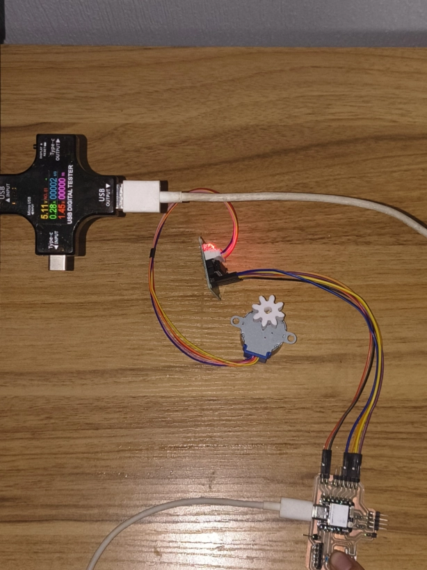
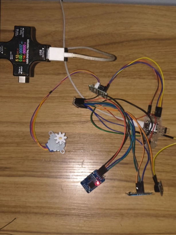
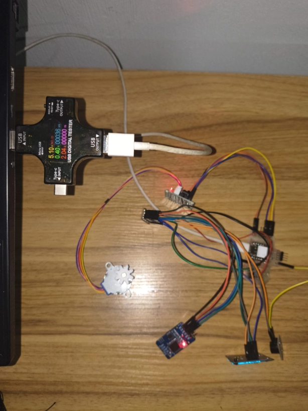
I measured the stepper motor alone to verify if the XIAO ESP32-C6 could power it safely through the ULN2003 driver. At peak movement it drew 0.28A, well within the USB-C power range (up to 1A)
With the complete system running (XIAO, OLED, RTC, stepper, and buzzer together) the current reached 0.39A with the motor moving. While at idle, the system consumes 0.02A, confirming that apagarMotor() works correctly and the device is safe for permanent wall power.
Even when I supposedly had the codes corrected and the mising step was just combining everything in the final assembly. Somethings didn't work as expected for example one button stopped working and the OLED didn't display the hour. Most of these problems were due to wiring confussion or slips, however its important to pay attention as we don't want to burn the components (I was scared that I almost burned the RTC). That is why I made a compilation of test codes to know if the components are functioning correctly.
/* PRUEBA PARA OLED INDIVIDUAL
//Si todo sale bien debería decir OK! La pantalla
#include <Wire.h>
#include <Adafruit_GFX.h>
#include <Adafruit_SH110X.h>
Adafruit_SH1106G display = Adafruit_SH1106G(128, 64, &Wire, -1);
void setup() {
Wire.begin(0, 1);
if (display.begin(0x3C, true)) {
display.clearDisplay();
display.setTextColor(SH110X_WHITE);
display.setTextSize(2);
display.setCursor(10, 20);
display.print("OK!");
display.display();
}
}
void loop() {} */
/*PRUEBA PARA RTC INDIVIDUAL
//Si todo sale bien debería aparecer OK! y después sincronizar la hora con la compu
#include <Wire.h>
#include <RTClib.h>
RTC_DS3231 rtc;
void setup() {
Serial.begin(115200);
Wire.begin(0, 1); // A mi me funciono sda en D0 y scl en D1
if (rtc.begin()) {
Serial.println("RTC encontrado OK");
// Esta función toma la hora de tu compu al momento de compilar
rtc.adjust(DateTime(F(__DATE__), F(__TIME__)));
Serial.println("Hora sincronizada con computadora");
} else {
Serial.println("RTC NO ENCONTRADO - revisa conexiones");
while (1); // Se detiene aqui
}
}
void loop() {
DateTime now = rtc.now();
Serial.print(now.day()); Serial.print("/");
Serial.print(now.month()); Serial.print("/");
Serial.print(now.year()); Serial.print(" ");
Serial.print(now.hour()); Serial.print(":");
if (now.minute() < 10) Serial.print("0");
Serial.print(now.minute()); Serial.print(":");
if (now.second() < 10) Serial.print("0");
Serial.println(now.second());
delay(5000); // Cada cuando aparece en el serial monitor esto es 5s
} */
//PRUEBA BOTONES ROJO Y AZUL
//Si todo sale bien debería aparecer que boton aprietas en el serial monitor
#define BTN_ROJO D4
#define BTN_AZUL D5
void setup() {
Serial.begin(115200);
pinMode(BTN_ROJO, INPUT_PULLUP);
pinMode(BTN_AZUL, INPUT_PULLUP);
Serial.println("Esperando botones...");
}
void loop() {
if (digitalRead(BTN_ROJO) == LOW) {
Serial.println("BOTON ROJO PRESIONADO");
delay(300); // antirrebote
}
if (digitalRead(BTN_AZUL) == LOW) {
Serial.println("BOTON AZUL PRESIONADO");
delay(200);
}
}
//OLED + Buttons
#include <Wire.h>
#include <Adafruit_GFX.h>
#include <Adafruit_SH110X.h>
Adafruit_SH1106G oled(128, 64, &Wire, -1);
void mostrar(const char* texto) {
oled.clearDisplay();
oled.setTextSize(3);
oled.setTextColor(SH110X_WHITE);
oled.setCursor(20, 20);
oled.print(texto);
oled.display();
}
void setup() {
Wire.begin(D0, D1);
oled.begin(0x3C, true);
pinMode(D4, INPUT_PULLUP); // boton azul
pinMode(D5, INPUT_PULLUP); // boton rojo
mostrar("...");
}
void loop() {
if (digitalRead(D4) == LOW) {
mostrar("AZUL");
while (digitalRead(D4) == LOW); // espera a que sueltes
}
if (digitalRead(D5) == LOW) {
mostrar("ROJO");
while (digitalRead(D5) == LOW); // espera a que sueltes
}
delay(20);
}
/* PRUEBA STEPPER MANUAL
//A continuación hay dos códigos, uno con control manual del stepper
// El motor avanza un paso cada 2ms pero el resto del código sigue corriendo, esto permite tener el OLED, RTC y buzzer funcionando al mismo tiempo.
// Pines del driver ULN2003
#define IN1 D7
#define IN2 D8
#define IN3 D9
#define IN4 D10
#define BOTON D2
// Secuencia de 8 pasos para motor 28BYJ-48 en modo half-step
// Cada fila es el estado de los 4 pines IN1,IN2,IN3,IN4
// El half-step da más suavidad y precisión que el full-step
int pasos[8][4] = {
{1,0,0,0}, // paso 1
{1,1,0,0}, // paso 2
{0,1,0,0}, // paso 3
{0,1,1,0}, // paso 4
{0,0,1,0}, // paso 5
{0,0,1,1}, // paso 6
{0,0,0,1}, // paso 7
{1,0,0,1} // paso 8
};
// Apaga las bobinas del motor para que no consuma corriente ni se caliente
void apagarMotor() {
digitalWrite(IN1, LOW);
digitalWrite(IN2, LOW);
digitalWrite(IN3, LOW);
digitalWrite(IN4, LOW);
}
// Activa los pines según la fila "p" de la tabla de pasos
void moverPaso(int p) {
digitalWrite(IN1, pasos[p][0]);
digitalWrite(IN2, pasos[p][1]);
digitalWrite(IN3, pasos[p][2]);
digitalWrite(IN4, pasos[p][3]);
}
bool moviendose = false; // true cuando el motor está en movimiento
int pasoActual = 0; // qué fila de la tabla toca ahora
int pasosRestantes = 0; // cuántos pasos faltan para terminar
unsigned long ultimoPaso = 0;// momento del último paso en ms
#define VELOCIDAD 2 // ms entre cada paso bajar = más rápido, subir = más lento
void setup() {
pinMode(IN1, OUTPUT);
pinMode(IN2, OUTPUT);
pinMode(IN3, OUTPUT);
pinMode(IN4, OUTPUT);
pinMode(BOTON, INPUT_PULLUP); // INPUT_PULLUP = reposo en HIGH, presionado en LOW
apagarMotor();
}
void loop() {
// Detectar botón
// Solo arranca si el motor no está ya moviéndose
if (digitalRead(BOTON) == LOW && !moviendose) {
delay(50); // antirrebote: espera 50ms y vuelve a leer
if (digitalRead(BOTON) == LOW) {
moviendose = true;
pasosRestantes = 1024; // 512 pasos = aprox media vuelta en 28BYJ-48
pasoActual = 0;
}
}
// Mover motor un paso a la vez sin bloquear
// En lugar de un for() con delay(), avanza UN solo paso
// cada vez que pasen VELOCIDAD milisegundos
// Así el loop() sigue corriendo y puede atender otras cosas
if (moviendose && millis() - ultimoPaso >= VELOCIDAD) {
ultimoPaso = millis();
moverPaso(pasoActual % 8); // % 8 para que el índice cicle 0-1-2-3-4-5-6-7-0-1...
pasoActual++;
pasosRestantes--;
if (pasosRestantes == 0) { // cuando termina
moviendose = false;
apagarMotor(); // apaga bobinas para no calentar
}
}
}*/
/* PRUEBA STEPPER CON LIBRERÍA ACCEL
#include <AccelStepper.h> // librería que maneja el motor con aceleración
#define IN1 D7
#define IN2 D8
#define IN3 D9
#define IN4 D10
#define BOTON D2
// HALF4WIRE = modo half-step con 4 pines
// El orden IN1,IN3,IN2,IN4 es importante — AccelStepper
// los intercala diferente al orden físico del ULN2003
AccelStepper motor(AccelStepper::HALF4WIRE, IN1, IN3, IN2, IN4);
bool moviendose = false; // true cuando el motor está en movimiento
void setup() {
pinMode(BOTON, INPUT_PULLUP);
motor.setMaxSpeed(1200); // velocidad máxima en pasos/segundo
motor.setAcceleration(800); // qué tan rápido acelera y desacelera
motor.disableOutputs(); // apaga los pines al inicio para no calentar
}
void loop() {
// ── Detectar botón ──────────────────────────────────
if (digitalRead(BOTON) == LOW && !moviendose) {
delay(100); // antirrebote
if (digitalRead(BOTON) == LOW) {
motor.enableOutputs(); // activa los pines del motor
motor.move(512); // programa un movimiento de 512 pasos
moviendose = true;
}
}
// ── Ejecutar movimiento ──────────────────────────────
// motor.run() avanza UN paso si es el momento correcto
// igual que el código manual pero la librería calcula
// automáticamente la aceleración y el timing
if (moviendose) {
motor.run();
if (motor.distanceToGo() == 0) { // distanceToGo() = pasos que faltan
moviendose = false;
motor.disableOutputs(); // apaga bobinas al terminar
}
}
}
/*PRUEBA SENSOR AVOID INDIVIDUAL
//Si todo sale bien al acercar un objeto detecta la banteja donde irian las pastillas
#define AVOID_PIN D3 // Pin del sensor Avoid IR
void setup() {
Serial.begin(115200);
pinMode(AVOID_PIN, INPUT);
}
void loop() {
// LOW = objeto detectado, HIGH = bandeja vacía
Serial.println(digitalRead(AVOID_PIN) == LOW ? "Bandeja detectada" : "Sin bandeja");
delay(200);
} */
/*PRUEBA FISICA TODOS LOS COMPONENTES EN SIMULTÁNEO
// A continuación está el código prueba o base del proyecto, sin complementarlo con el código de Networking (HTTP con ESP32).
//
#include <AccelStepper.h>
#include <Wire.h>
#include <Adafruit_GFX.h>
#include <Adafruit_SH110X.h>
#include <RTClib.h>
#include <WiFi.h>
#include <WebServer.h>
#define IN1 D7
#define IN2 D8
#define IN3 D9
#define IN4 D10
#define BOTON_AZU D5
#define BOTON_ROJ D4
#define BUZZER D6
#define I2C_SDA 0
#define I2C_SCL 1
Adafruit_SH1106G display = Adafruit_SH1106G(128, 64, &Wire, -1);
RTC_DS3231 rtc;
AccelStepper motor(AccelStepper::HALF4WIRE, IN1, IN3, IN2, IN4);
WebServer server(80);
#define NOMBRE "PillDispenser-MJ"
#define WIFI_PASS "fabacademy"
#define MX 6
#define MW 116
bool isEnglish = true;
int alarmaAMhora = -1, alarmaAMmin = -1;
int alarmaPMhora = -1, alarmaPMmin = -1;
bool alarmaActiva = false;
bool moviendose = false;
bool preguntaPosponer = false; // esperando confirmación del botón rojo
unsigned long pospuestaEn = 0;
bool pospuesto = false;
unsigned long ultimoBeep = 0;
int faseBeep = 0;
String dosis_activa = "";
struct Entrada { char texto[20]; bool activo = false; };
Entrada histAlarmas[5];
Entrada histDosis[5];
int idxA = 0, idxD = 0;
void agregarHistAlarma(String s) { strncpy(histAlarmas[idxA].texto,s.c_str(),19); histAlarmas[idxA].activo=true; idxA=(idxA+1)%5; }
void agregarHistDosis (String s) { strncpy(histDosis [idxD].texto,s.c_str(),19); histDosis [idxD].activo=true; idxD=(idxD+1)%5; }
String dosStr(int h, int m) {
if (h < 0) return "--:--";
char buf[6]; sprintf(buf,"%02d:%02d",h,m); return String(buf);
}
// Corrección del bug AM/PM: Calcula el tiempo más cercano en minutos reales
String proximaDosis(DateTime now) {
if (alarmaAMhora < 0 && alarmaPMhora < 0) return isEnglish ? "No alarms" : "Sin alarmas";
int ahoraEnMinutos = now.hour() * 60 + now.minute();
int amEnMinutos = (alarmaAMhora >= 0) ? (alarmaAMhora * 60 + alarmaAMmin) : -1;
int pmEnMinutos = (alarmaPMhora >= 0) ? (alarmaPMhora * 60 + alarmaPMmin) : -1;
int diffAM = -1, diffPM = -1;
if (amEnMinutos >= 0) {
diffAM = amEnMinutos - ahoraEnMinutos;
if (diffAM <= 0) diffAM += 1440; // Si ya pasó, será mañana
}
if (pmEnMinutos >= 0) {
diffPM = pmEnMinutos - ahoraEnMinutos;
if (diffPM <= 0) diffPM += 1440; // Si ya pasó, será mañana
}
// Decidir cuál está más cerca en el tiempo real
if (diffAM >= 0 && (diffPM < 0 || diffAM < diffPM)) {
return "AM " + dosStr(alarmaAMhora, alarmaAMmin);
} else {
return "PM " + dosStr(alarmaPMhora, alarmaPMmin);
}
}
// ── OLED helpers ──
void oledCentro(int y, int size, String txt) {
display.setTextSize(size);
int charW = size * 6;
int x = MX + (MW - (int)txt.length()*charW) / 2;
if (x < MX) x = MX;
display.setCursor(x, y);
display.print(txt);
}
void oledNormal(DateTime now) {
display.clearDisplay();
display.setTextColor(SH110X_WHITE);
char hora[6]; sprintf(hora,"%02d:%02d",now.hour(),now.minute());
oledCentro(14, 3, String(hora));
char fecha[11]; sprintf(fecha,"%02d/%02d/%04d",now.day(),now.month(),now.year());
oledCentro(40, 1, String(fecha));
String prox = (isEnglish ? "Next: " : "Prox: ") + proximaDosis(now);
oledCentro(52, 1, prox);
display.display();
}
void oledAlarma() {
display.clearDisplay();
display.setTextColor(SH110X_WHITE);
oledCentro(10, 1, isEnglish ? "TAKE YOUR PILLS" : "TOMA TUS PASTILLAS"); // Tamaño reducido de 2 a 1 para que no esté muy grande
oledCentro(26, 1, (isEnglish ? "Dose: " : "Dosis: ") + dosis_activa);
oledCentro(40, 1, isEnglish ? "Blue=take" : "Azul=tomar");
oledCentro(52, 1, isEnglish ? "Red=snooze" : "Rojo=posponer");
display.display();
}
void oledPosponer() {
display.clearDisplay();
display.setTextColor(SH110X_WHITE);
oledCentro(8, 1, isEnglish ? "Snooze 10 min?" : "Posponer 10min?");
oledCentro(26, 1, isEnglish ? "Short = YES" : "Corto = SI");
oledCentro(38, 1, isEnglish ? "Long = NO" : "Largo = NO");
display.display();
}
void oledMensaje(String l1, String l2, String l3="") {
display.clearDisplay();
display.setTextColor(SH110X_WHITE);
int y = l3=="" ? 20 : 10;
oledCentro(y, 1, l1);
oledCentro(y+14, 1, l2);
if (l3!="") oledCentro(y+28, 1, l3);
display.display();
}
// ── Enlaces de ejecución directa ──
void ejecutarToma() {
alarmaActiva=false; noTone(BUZZER); faseBeep=0; pospuesto=false; preguntaPosponer=false;
motor.enableOutputs(); motor.move(512); moviendose=true;
// Guardar en el historial que se tomó la dosis de forma específica
char buf[20]; sprintf(buf, "%s Taken", dosis_activa.c_str());
agregarHistDosis(String(buf));
oledMensaje(isEnglish?"Dispensing...":"Dispensando...","");
}
void ejecutarPosponer() {
pospuesto=true; pospuestaEn=millis();
alarmaActiva=false; preguntaPosponer=false; faseBeep=0; noTone(BUZZER);
// Guardar en el historial que se pospuso la dosis de forma específica
char buf[20]; sprintf(buf, "%s Snoozed", dosis_activa.c_str());
agregarHistDosis(String(buf));
}
// ── Buzzer ──
void sonarConfirmacion() {
tone(BUZZER, 2700, 80); delay(120);
tone(BUZZER, 2700, 150); delay(200);
}
void tickBeep() {
unsigned long t = millis();
if (t - ultimoBeep < 150) return;
ultimoBeep = t; faseBeep++;
if (faseBeep == 1) tone(BUZZER, 2700, 120);
else if (faseBeep == 2) noTone(BUZZER);
else if (faseBeep == 3) tone(BUZZER, 2700, 120);
else if (faseBeep == 4) noTone(BUZZER);
else if (faseBeep == 5) tone(BUZZER, 2700, 120);
else if (faseBeep >= 6) { noTone(BUZZER); faseBeep = 0; ultimoBeep = t + 400; }
}
// ── Web ──
void handleRoot() {
DateTime now = rtc.now();
char nowStr[9]; sprintf(nowStr,"%02d:%02d:%02d",now.hour(),now.minute(),now.second());
bool EN = isEnglish;
String s = "<!DOCTYPE html><html><head><meta charset='UTF-8'>";
s += "<meta name='viewport' content='width=device-width,initial-scale=1'>";
s += "<title>" + String(NOMBRE) + "</title><style>";
s += "body{font-family:'Inter',sans-serif;background:#ede8e6;margin:0;padding-bottom:40px;text-align:center;}";
s += ".navbar{background:#fff;padding:14px;display:flex;justify-content:center;gap:10px;box-shadow:0 2px 10px rgba(0,0,0,.05);}";
s += ".btn{background:#2f6df6;color:#fff;border:none;padding:11px 22px;border-radius:50px;text-decoration:none;font-weight:700;font-size:13px;display:inline-block;cursor:pointer;}";
s += ".btn.gray{background:#666;} .btn.red{background:#e53935;} .btn.green{background:#2e7d32;}";
s += ".container{max-width:400px;margin:18px auto;background:#fff;padding:24px;border-radius:28px;box-shadow:0 8px 24px rgba(0,0,0,.07);}";
s += ".lbl{font-size:.75rem;font-weight:800;color:#aaa;text-transform:uppercase;letter-spacing:1px;display:block;margin-bottom:6px;}";
s += ".clock{font-size:3rem;color:#2f6df6;font-weight:800;margin:4px 0;}";
s += ".prox{font-size:.9rem;color:#555;margin:4px 0 10px;}";
s += ".grid2{display:grid;grid-template-columns:1fr 1fr;gap:10px;margin:12px 0;}";
s += "input[type=time]{width:100%;padding:10px;border-radius:50px;border:2px solid #2f6df6;font-size:1rem;box-sizing:border-box;text-align:center;margin-bottom:8px;}";
s += "input[type=submit]{background:#1c1c1c;color:#fff;border:none;padding:10px;border-radius:50px;width:100%;font-size:.85rem;font-weight:700;cursor:pointer;}";
s += ".log-row{display:grid;grid-template-columns:1fr 1fr;gap:10px;margin-top:10px;text-align:left;}";
s += ".log-box{background:#fafafa;padding:14px;border-radius:18px;border:1px solid #eee;font-size:.83rem;}";
s += ".banner{background:#fff3cd;border:2px solid #ffc107;border-radius:14px;padding:12px;margin:10px 0;font-size:.9rem;}";
s += "</style><script>let t=false;setInterval(()=>{if(!t)location.reload();},1000);</script></head><body>";
// Navbar
s += "<div class='navbar'>";
s += "<a href='/' class='btn'>Home</a>";
s += "<a href='/toggleLang' class='btn gray'>" + String(EN?"Español":"English") + "</a>";
s += "<a href='/reset' class='btn red'>Reset</a>";
s += "</div>";
// Reloj
s += "<div class='container'>";
s += "<span class='lbl'>" + String(EN?"CURRENT TIME":"HORA ACTUAL") + "</span>";
s += "<div class='clock'>" + String(nowStr) + "</div>";
s += "<div class='prox'>" + String(EN?"Next dose: ":"Próxima dosis: ") + "<b>" + proximaDosis(now) + "</b></div>";
if (alarmaActiva) {
s += "<div class='banner'><b>" + String(EN?"TAKE YOUR PILLS":"TOMA TUS PASTILLAS") + "</b> — " + dosis_activa + "</div>"; // Emoji removido
// Botones invertidos: Primero Snooze (Rojo) y después Take (Verde)
s += "<div class='grid2'>";
s += "<a href='/webSnooze' class='btn red'>" + String(EN?"Snooze 10m":"Posponer 10m") + "</a>";
s += "<a href='/webTake' class='btn green'>" + String(EN?"Take Pill":"Tomar Pastilla") + "</a>";
s += "</div>";
}
s += "</div>";
// Alarmas personalizadas organizadas en 2 columnas con guardado independiente cada una
s += "<div class='container'>";
s += "<span class='lbl'>" + String(EN?"CUSTOM ALARM":"HORA PERSONALIZADA") + "</span>";
s += "<div class='grid2'>";
// Columna AM
s += "<div>";
s += "<form action='/setAlarmas' method='GET' onsubmit='t=false'>";
s += "<label style='font-size:.8rem;color:#888;font-weight:bold;'>AM</label>";
s += "<input type='time' name='am' value='" + (alarmaAMhora>=0?dosStr(alarmaAMhora,alarmaAMmin):"") + "' onfocus='t=true' onblur='t=false'>";
s += "<input type='submit' value='" + String(EN?"Save AM":"Guardar AM") + "'>";
s += "</form>";
s += "</div>";
// Columna PM
s += "<div>";
s += "<form action='/setAlarmas' method='GET' onsubmit='t=false'>";
s += "<label style='font-size:.8rem;color:#888;font-weight:bold;'>PM</label>";
s += "<input type='time' name='pm' value='" + (alarmaPMhora>=0?dosStr(alarmaPMhora,alarmaPMmin):"") + "' onfocus='t=true' onblur='t=false'>";
s += "<input type='submit' value='" + String(EN?"Save PM":"Guardar PM") + "'>";
s += "</form>";
s += "</div>";
s += "</div></div>";
// Historial
s += "<div class='container'><span class='lbl'>" + String(EN?"HISTORY":"HISTORIAL") + "</span>";
s += "<div class='log-row'>";
s += "<div class='log-box'><b>" + String(EN?"Alarms":"Alarmas") + "</b><br>";
for (int i=0;i<5;i++) { int idx=(idxA-1-i+5)%5; if(histAlarmas[idx].activo) s+="• "+String(histAlarmas[idx].texto)+"<br>"; }
s += "</div><div class='log-box'><b>" + String(EN?"Doses Log":"Registro Dosis") + "</b><br>";
for (int i=0;i<5;i++) { int idx=(idxD-1-i+5)%5; if(histDosis[idx].activo) s+="• "+String(histDosis[idx].texto)+"<br>"; }
s += "</div></div></div>";
s += "</body></html>";
server.send(200,"text/html",s);
}
// Guarda de forma totalmente aislada la alarma que se envió
void handleSetAlarmas() {
if (server.hasArg("am")) {
String am = server.arg("am");
if (am != "") { alarmaAMhora=am.substring(0,2).toInt(); alarmaAMmin=am.substring(3,5).toInt(); agregarHistAlarma("AM "+am); }
else { alarmaAMhora = -1; alarmaAMmin = -1; }
}
if (server.hasArg("pm")) {
String pm = server.arg("pm");
if (pm != "") { alarmaPMhora=pm.substring(0,2).toInt(); alarmaPMmin=pm.substring(3,5).toInt(); agregarHistAlarma("PM "+pm); }
else { alarmaPMhora = -1; alarmaPMmin = -1; }
}
server.sendHeader("Location","/"); server.send(303);
}
void handleToggleLang() { isEnglish=!isEnglish; server.sendHeader("Location","/"); server.send(303); }
void handleReset() {
alarmaAMhora=alarmaAMmin=alarmaPMhora=alarmaPMmin=-1;
alarmaActiva=pospuesto=preguntaPosponer=false;
faseBeep=0; noTone(BUZZER);
for(int i=0;i<5;i++){histAlarmas[i].activo=false;histDosis[i].activo=false;}
server.sendHeader("Location","/"); server.send(303);
}
void handleWebTake() { if(alarmaActiva){ ejecutarToma(); } server.sendHeader("Location","/"); server.send(303); }
void handleWebSnooze() { if(alarmaActiva){ ejecutarPosponer(); } server.sendHeader("Location","/"); server.send(303); }
void leerSerial() {
if (!Serial.available()) return;
String cmd=Serial.readStringUntil('\n'); cmd.trim(); cmd.toUpperCase();
if (cmd.length()<10||cmd.charAt(4)!=' '){Serial.println("[ERROR] ALAM hh:mm | ALPM hh:mm");return;}
String tipo=cmd.substring(0,4);
if (tipo!="ALAM"&&tipo!="ALPM"){Serial.println("[ERROR] Usa ALAM o ALPM");return;}
int sep=cmd.indexOf(':');
int hh=cmd.substring(5,sep).toInt(), mm=cmd.substring(sep+1).toInt();
if (hh<1||hh>12||mm<0||mm>59){Serial.println("[ERROR] hh:1-12 mm:00-59");return;}
if (tipo=="ALAM"){if(hh==12)hh=0;alarmaAMhora=hh;alarmaAMmin=mm;agregarHistAlarma("AM "+dosStr(hh,mm));Serial.print("[OK] AM: ");Serial.println(dosStr(hh,mm));}
else {if(hh!=12)hh+=12;alarmaPMhora=hh;alarmaPMmin=mm;agregarHistAlarma("PM "+dosStr(hh,mm));Serial.print("[OK] PM: ");Serial.println(dosStr(hh,mm));}
}
void chequearAlarmas(DateTime now) {
if (alarmaActiva||moviendose||pospuesto) return;
if (now.second()!=0) return;
if (alarmaAMhora>=0&&now.hour()==alarmaAMhora&&now.minute()==alarmaAMmin){alarmaActiva=true;dosis_activa="AM";faseBeep=0;}
if (alarmaPMhora>=0&&now.hour()==alarmaPMhora&&now.minute()==alarmaPMmin){alarmaActiva=true;dosis_activa="PM";faseBeep=0;}
}
void setup() {
Serial.begin(115200);
Wire.begin(I2C_SDA,I2C_SCL);
Wire.setClock(100000);
pinMode(BOTON_AZU,INPUT_PULLUP);
pinMode(BOTON_ROJ,INPUT_PULLUP);
pinMode(BUZZER,OUTPUT);
display.begin(0x3C,true);
display.setTextColor(SH110X_WHITE);
display.clearDisplay();
oledMensaje("Iniciando...","");
display.display();
if (!rtc.begin()) { oledMensaje("Error RTC",""); while(1); }
rtc.adjust(DateTime(F(__DATE__),F(__TIME__)));
motor.setMaxSpeed(1200); motor.setAcceleration(800); motor.disableOutputs();
WiFi.softAP(NOMBRE, WIFI_PASS);
server.on("/", handleRoot);
server.on("/setAlarmas", handleSetAlarmas);
server.on("/toggleLang", handleToggleLang);
server.on("/reset", handleReset);
server.on("/webTake", handleWebTake);
server.on("/webSnooze", handleWebSnooze);
server.begin();
Serial.print("IP: "); Serial.println(WiFi.softAPIP());
tone(BUZZER,1000,100); delay(150);
tone(BUZZER,1500,100); delay(150);
tone(BUZZER,2000,200); delay(300);
}
void loop() {
server.handleClient();
leerSerial();
DateTime now = rtc.now();
chequearAlarmas(now);
// ── Alarma activa ──
if (alarmaActiva && !moviendose) {
tickBeep();
if (preguntaPosponer) oledPosponer();
else oledAlarma();
if (!preguntaPosponer && digitalRead(BOTON_AZU)==LOW) {
delay(80);
if (digitalRead(BOTON_AZU)==LOW) {
ejecutarToma();
}
}
if (digitalRead(BOTON_ROJ)==LOW) {
delay(80);
if (digitalRead(BOTON_ROJ)==LOW) {
if (!preguntaPosponer) {
preguntaPosponer = true;
noTone(BUZZER);
} else {
unsigned long ini = millis();
while (digitalRead(BOTON_ROJ)==LOW) delay(10);
unsigned long dur = millis()-ini;
if (dur < 800) {
ejecutarPosponer();
Serial.println(isEnglish?"[SNOOZE] 10 min":"[POSPONER] 10 min");
} else {
preguntaPosponer=false;
}
}
}
}
return;
}
// ── Reactivar pospuesto ──
if (pospuesto && millis()-pospuestaEn>=600000UL) {
pospuesto=false; alarmaActiva=true; faseBeep=0;
}
// ── Motor ──
if (moviendose) {
motor.run();
if (motor.distanceToGo()==0) {
moviendose=false; motor.disableOutputs(); sonarConfirmacion();
oledMensaje(isEnglish?"Thanks for taking":"Gracias por tomar", isEnglish?"your pills":"tus pastillas");
delay(2500);
}
return;
}
static unsigned long lastDisp=0;
if (millis()-lastDisp>=500) { oledNormal(now); lastDisp=millis(); }
delay(40);
} */
When I ran the final code the buttons didn't responded, nor the OLED. So I first checked the buttons becuase the jumpers were soldered to the buttons its union was a bit fragile, so one of the legs snapped, while the other button loosened up while assembling. Also the driver for the stepper started blinking meaning there is either a thermal shutdown or shorcircuit. So I disconected everything, and ran individual test for each component.
These are the correct connections for all the components to work with the final code.
| Component | Signal pin | VCC | GND | Connection / note |
|---|---|---|---|---|
| XIAO ESP32-C6 | - | USB-C / 5V input | Common GND | Main controller. All modules must share GND with the XIAO. |
| OLED SH1106 | SDA = D0 / GPIO0, SCL = D1 / GPIO1 | 3V3 | GND | I2C display connected through the I2C hub board. |
| DS3231 RTC | SDA = D0 / GPIO0, SCL = D1 / GPIO1 | 3V3 | GND | Shares the same I2C hub board as the OLED. |
| Blue button / confirm function | D5 | - | GND | BOTON_AZU in the final code. Connect one side to D5 and the other to GND. The code uses INPUT_PULLUP. |
| Red button | D4 | - | GND | BOTON_ROJ. Connect one side to D4 and the other to GND. The code uses INPUT_PULLUP. |
| Passive buzzer | D6 | 3V3 | GND | BUZZER. Signal is controlled from D6 and the module is powered from 3V3. |
| ULN2003 IN1 | D7 | 5V from XIAO | GND shared with XIAO | Stepper driver input 1. |
| ULN2003 IN2 | D8 | 5V from XIAO | GND shared with XIAO | Stepper driver input 2. |
| ULN2003 IN3 | D9 | 5V from XIAO | GND shared with XIAO | Stepper driver input 3. |
| ULN2003 IN4 | D10 | 5V from XIAO | GND shared with XIAO | Stepper driver input 4. |
| 28BYJ-48 stepper motor | ULN2003 output connector | From ULN2003 | From ULN2003 | Connect the motor to the ULN2003 board. |
In the first test, the buttons weren't connected correctly. The board only detected one of them, and the response was inverted because I accidentally swapped the button pins. After fixing the wiring, each button worked as expected: when I pressed the button of each color, the OLED showed that color, and when nothing was pressed it showed three dots (...).
I tested a KY-032 Avoid IR sensor from an Arduino kit to see if it could confirm whether the pills fell after dispensing. However, the pill drop is easy to see, so another possible use would be detecting if the small tray was moved after the pills fell. For this prototype it felt redundant because the pills dispense only after confirmation, and during my grandfather's breakfast and dinner someone is usually nearby.
To integrate it, the cables would need to leave the enclosure and the sensor would have to be hidden at a very specific distance. In this test, when my hand got close to the sensor, the module detected the object and its onboard LED turned on.
/* PRUEBA SENSOR AVOID INDIVIDUAL
// Si todo sale bien, al acercar un objeto detecta la bandeja donde irian las pastillas.
// Note: on this sensor module, the onboard LED turns on when an object is detected.
#define AVOID_PIN D3 // Pin del sensor KY-032 Avoid IR
void setup() {
Serial.begin(115200);
pinMode(AVOID_PIN, INPUT);
}
void loop() {
// LOW = objeto detectado, HIGH = bandeja vacia
Serial.println(digitalRead(AVOID_PIN) == LOW ? "Bandeja detectada" : "Sin bandeja");
delay(200);
}
All these interacions helped me understand better the components and prepare for the final integration, that is a combination of previous weeks work and improvements. This is the final Arduino code used for the dispenser, including the alarms, OLED display, buttons, buzzer, stepper movement, and web interface.
Please note that it was developed with the assistance of Claude which helped me debug, structure, and iteratively improve the code through conversation. All design decisions and testing were carried out by me throughout the Fab Academy process. Some of thse decisions include hardware adjustments in the next tab.
One important detail I missed while designing the overall project and physical pieces, was the space for electronics, evethough I planned and designated measurements for the components. I forgot to visualize the jumpers heads. It may not sound a lot, but it affected the OLED display as teh pieces wouldn't fit propperly, so, I decided to change the direcction from the pin headers of the OLED.
The overal procces was applying flux, heating the soldering and remove the default pin headers. Then change them for 90-degree pin headers. This need to be done carefully to avoid damaging the component. At the end it help me a lot making this change, this ways the cables don't interfiere with the tolerances and fitting.
Another challenge was soldering the buttons directly to cables. The push buttons have 4 legs, but only 2 are used: the diagonal pins corresponding to GND and Signal. To do this, I peeled the wire ends, slid heat shrink tubingon before soldering (dont forget or you might have to desolder it/use insulation tape), then I covered the joint to protect it.
I also soldered both GND cables together into a single wire since both buttons share the same ground, reducing the cable count and freeing up a pin slot. Finally, I used a crimping tool to add Dupont connectors, converting the cables into jump wires for easier connection to the PCB. In the future, I would like to design a small breakout board for cleaner cable management.
When I first designed the PCB I soldered wrong the neopixel and while trying to re-solder. I damaged its route and endep up eliminating the neopixel. However, when I was deciding whether or not implement the IR sennsor, I realized that the GPIO dedicated to the dead neopixel could be used for anither componnt if a pin header was solder. I also change the female pin headers thought for potentiometers for 90-degree pin headers.
In the future I would like to improve the PCB design, to include a Lipo Bat (for emergency power backup), the servo sliding door and the IR sensor. So I might have to change the microcrontoller. But for this occation, the "modular" (at the end it was not modular but pretty adaptable for my needs) PCB worked just fine.
For the removable acrylic cover I used 5 x 3 mm neodymium magnets. The first holes were too tight, so I adjusted the 3D printed tolerance to 0.4 mm. I only used glue for the magnets, because over time they could loosen with repeated opening and closing. In the rest of the assembly I tried to avoid glue so the dispenser can be disassembled, repaired, or modified later. The other place where I used adhesive was the cork detail on the wooden base.
The small acrylic and OLED center details were assembled with M1.6 screws. They are very small, but they worked well for the compact parts where a larger screw would not fit. For everything attached to the wooden base I used M6 screws in different lengths. First I measured the center point where each screw needed to go, made a small pilot hole with a drill, and then used an electric screwdriver to fasten the pieces. Having the 3D printed hole slightly smaller than the screw helped the screw grip better and made the assembly feel tighter.
The OLED is held in the printed center piece with a snap fit. This worked for the final prototype and avoided adding extra glue around the screen, which makes the part easier to repair or redesign. The snap fit could still be improved so the insertion feels smoother and less forced.
In a future version I would like to test heat-set inserts again. My first idea was to use nuts or threaded inserts, but I did not have the correct heat-set inserts at the time, so the snap fit became the most practical solution for this prototype.
This video shows the first full body assembly, including the printed dispenser body, CNC routed wooden base, motor position, and the way the mechanical parts start fitting together. I also braided the cables by component so the wiring would be easier to route and identify. When possible, I tried to keep similar colors for the same type of connection: black and gray for GND, red and orange for VCC, and other colors for signal lines.
The final validation test shows the dispenser working as an integrated system: the interface, OLED, alarm, button confirmation, motor movement, carousel alignment, and pill release all working together.
No. In the final calibration, one compartment needed around 1030 steps to align correctly and dispense reliably.
Yes. The final mechanism lets the pills fall by gravity through the acrylic opening when the carousel aligns with the exit.
It works, but it could be improved. A stronger buzzer or a small amplifier could make the alarm louder and easier to hear.
Yes. The magnets hold the cover in place, but it can still be removed easily when the dispenser needs to be refilled.
Yes. The complete system worked from one USB-C charger during the final integration tests.
Yes. The XIAO can run the access point interface while controlling the alarm, OLED, buttons, and motor. A future improvement would be testing a WiFi web server or a combined version that can send Telegram messages to relatives if the dose is not taken.
Not for this version. Since the user confirms the dose manually, the sensor adds more complexity than value. It could be useful later in a more automated version.
Yes. The interaction is understandable, and I also added vinyl labels to make the buttons clearer for the user.
Magnets and snap fits could help make the ring modular, easier to remove, and easier to replace or adapt in future versions.
| Component | Purpose | Qty | Source | Cost MXN | Cost USD |
|---|---|---|---|---|---|
| XIAO ESP32-C6 | Main controller | 1 | Provided by Fab Lab Puebla / Uelectronics reference price | $137 | $7.61 |
| DS3231 RTC module | Real time clock | 1 | Amazon MX reference price | $95 | $5.28 |
| SH1106 OLED 128 x 64 | User display | 1 | Amazon MX reference price | $110 | $6.11 |
| 28BYJ-48 with ULN2003 | Carousel motor | 1 | Amazon MX reference price | $80 | $4.44 |
| Passive buzzer | Alarm sound | 1 | From a small Arduino starter kit | $15 | $0.83 |
| Tactile push buttons | Confirm and snooze | 2 | Purchased | $10 | $0.56 |
| FR1 copper board | PCB substrate | 1 sheet | Fab Lab Puebla | $60 | $3.33 |
| PLA filament | 3D printed parts | Approx. 0.7 kg | Fab Lab Puebla | $280 | $15.56 |
| 3 mm acrylic sheet | Laser cut cover | 1 piece | Already owned | $45 | $2.50 |
| 9 mm plywood | CNC routed base | 1 piece | Recycled material | $50 | $2.78 |
| Cork sheet | Laser cut cover for plywood detail | 1 small piece | Already owned | $15 | $0.83 |
| Adhesive vinyl | Button labels | 1 small piece | Fab Lab Puebla | $10 | $0.56 |
| Neodymium magnets 5 x 3 mm | Removable acrylic cover closure | 18 | Amazon MX reference price | $180 | $10.00 |
| M1.6 screws | Small acrylic and OLED center piece assembly | Assorted | Already owned | $35 | $1.94 |
| M6 screws | Fastening printed parts to the wooden base | Assorted lengths | Already owned | $45 | $2.50 |
| 90-degree male pin headers | PCB connections and modified OLED/header orientation | 10 pins | Fab Lab from the university | $25 | $1.39 |
| 240 Ω SMD resistor 1206 | PCB resistor used in the Week 10 board | 1 | Fab Lab from the university | $2 | $0.11 |
| Dupont jumper wires | Module wiring and final electronics integration | Assorted | Fab Lab from the university | $45 | $2.50 |
| Dupont housings and crimp terminals | Button and modular cable connections | Assorted | Fab Lab from the university | $40 | $2.22 |
| Heat shrink tubing | Button solder joint insulation | Assorted | Fab Lab from the university | $20 | $1.11 |
| Adhesive | Securing magnets and cork only | Small amount | Lab inventory | $20 | $1.11 |
| USB C 5 V charger | Power supply | 1 | Already owned | $0 | $0.00 |
| Total estimated | $1,319 MXN | $73.28 USD | |||
These are estimated replacement costs, even when some materials were provided, recycled, or already owned. USD values are approximate, calculated with an estimated exchange rate of 1 USD = 18 MXN. The 10 kΩ resistor from the Week 10 test board was not included because it was related to a test feature that was not used in the final project.
One of the biggest things I learned is that there is always something that can be improved. This project started years ago as a high school idea, and I honestly never imagined I would be able to revisit it at this level: with electronics, digital fabrication, programming, networking, documentation, and a working prototype.
I made many mistakes during the process, and the final system can still improve, but it represents a huge step forward for me. Before Fab Academy, I knew very little about programming and electronics, and even now I know there is still a lot to learn. However, this project showed me that learning doesn't happen only by getting things right. It also happens by asking questions, testing, failing, researching by myself, and learning from the people around me. It also changed the way I understand documentation. Sometimes small changes, tiny mistakes, or simple decisions feel unimportant in the moment, but later they can help us or someone else understand the process better, documenting became another way of learning (very tedious but worthy)
I also want to thank my professors and local evaluator from Fab Lab Puebla, my friends and my family that helped and supported one another throughout this journey, making the process a lot more enjoyable.
This documentation and project files are shared for learning, remixing, and non-commercial adaptation with attribution.