Week 12 Group Assignment - Machine Design and Building
This week's assignment was to design a machine that includes mechanism, actuation,
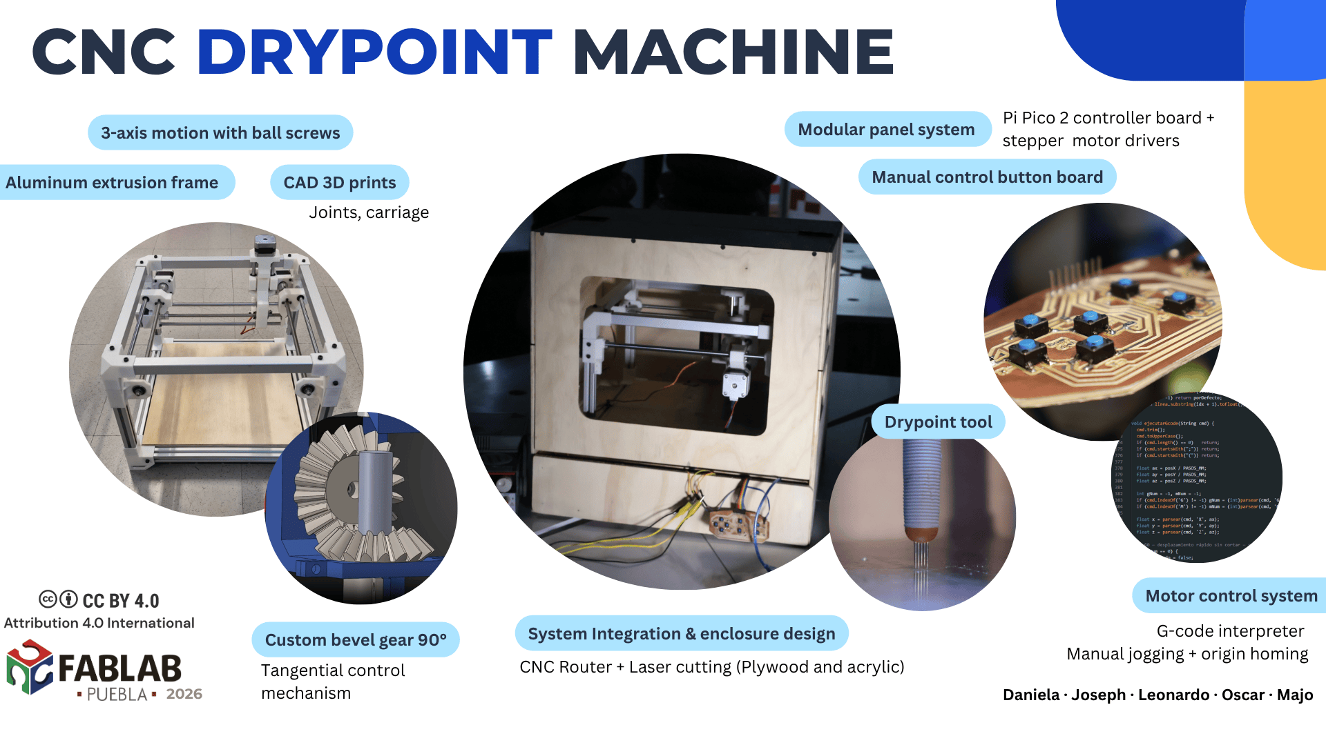
automation, function, and a user interface. The result was a engraving CNC machine for drypoint a technique used in printmaking where a pattern is reproduced into a metal plate with a hard-pointed tool.
Within the collaborative project, our primary focus for the mechanical system was the design and fabrication of a robust structure. Since metal engraving and scratching require considerable cutting force, we designed the motion transmission system using ball screws (lead screws) to ensure the necessary mechanical advantage and thrust. To achieve the required structural rigidity while maintaining the build's modularity, we constructed the main frame using aluminum extrusion profiles combined with custom 3D-printed joints and supports.
CNC Machine Mechanical Results
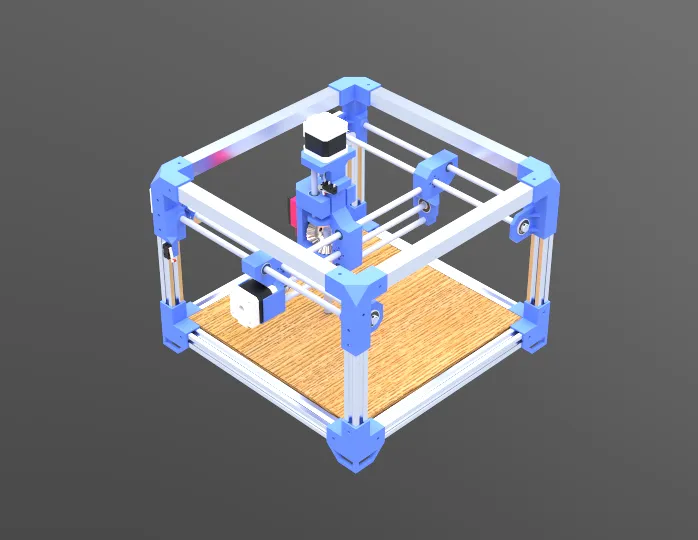
The final design consists of a 3-axis CNC machine, where the toolhead moves along the X, Y, and Z axes to perform precise engraving operations, while the workpiece is held in place by a custom fixture with metal clamps. The pieces were modeled in SolidWorks to create the assembly of the CNC machine.
The digital model helped us visualize the complete mechanism, define measurements, and confirm that all parts were properly aligned before fabrication.
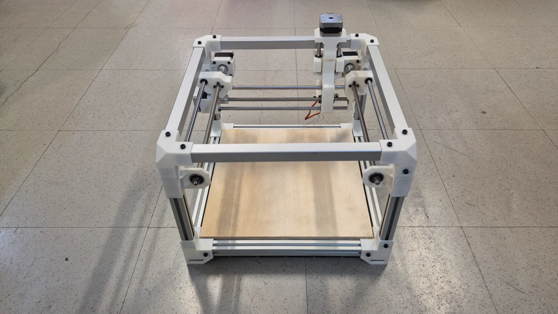
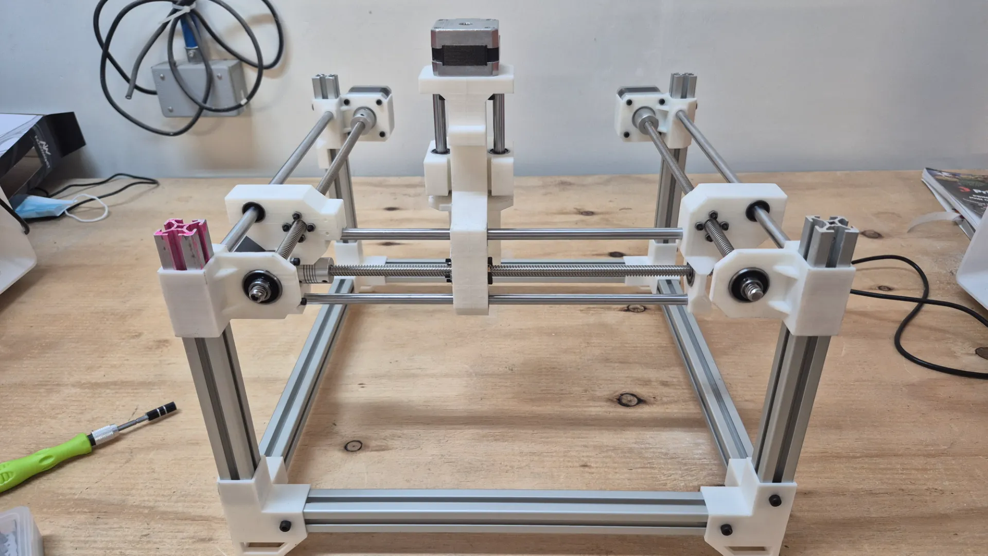
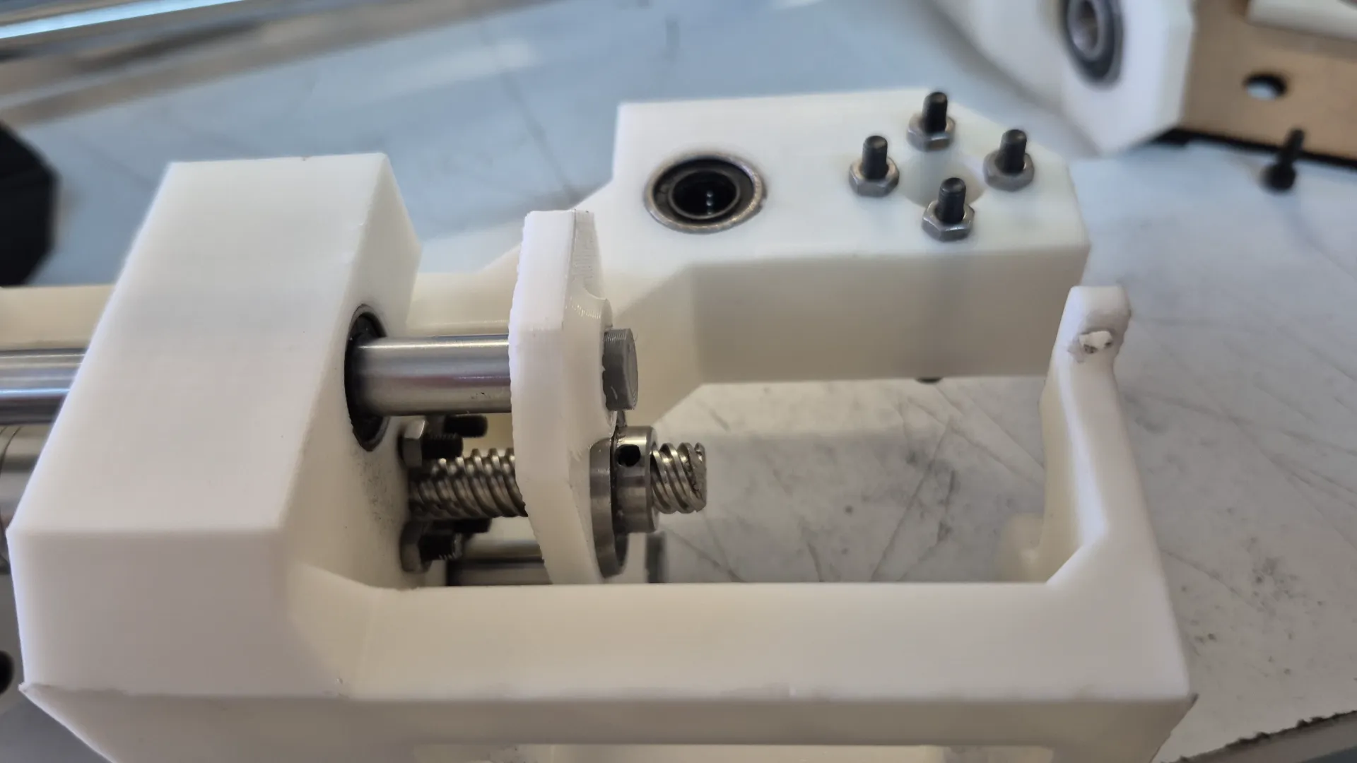
Here is a image of the physical assembly of the machine. Building the structure in real life allowed us to validate the fit of the components and verify that the mechanical system matched the planned design.
Bill of Materials
To keep the project organized and replicable, we compiled a comprehensive Bill of Materials that is divided into off-the-shelf purchased components and custom-fabricated parts produced in the lab.
Purchased Components (Off-the-shelf)
Qty
Component
Details
4
NEMA Stepper Motors
For X, Y, and Z axis movement
4
Flexible Couplers
Connects NEMA motor shafts to the lead screws
8
Aluminum Extrusion Profiles
Main structural frame. Cut lengths: 4x 300 mm and 4x 190 mm
4
Square Tubing
Additional structural support. Cut lengths: 4x 300 mm
6
Linear Guide Rods
Smooth steel rods. Cut lengths: 2x 305 mm, 1x 292 mm, 1x 260 mm, and 2x 87 mm
4
Lead Screws
Threaded rods for motion. Cut lengths: 2x 320 mm, 1x 272 mm, and 1x 75 mm
4
Brass Lead Screw Nuts
Couples the carriage to the lead screw
6
Linear Bearings
For smooth travel along the guide rods
4
Mounted Bearings with Set Screws
To securely hold the ends of the lead screws
32
M4 x 6mm Screws
Fasteners
20
M4 x 10mm Screws
Fasteners
12
M3 x 8mm Screws
Fasteners
8
M3 x 16mm Screws
Fasteners
16
M3 x 30mm Screws
Fasteners
#
Respective nuts for each screw
Fasteners
Fabricated Components
Qty
Component
Details
1 Set
Custom Joints, and Motor Mounts
3D Printed (PLA)
1 Set
X, Y, and Z Axis Carriages
3D Printed (PLA)
1
Machine Bed
Cut MDF & Plywood
4
Workholding Clamps
Fabricated Metal
CAD Design for custom pieces
The custom 3D-printed parts for the project include corner joints, motor mounts, tool carriage and a custom 90-degree bevel gear transmission. In the following carousel, we have arranged images of the main components designed and manufactured for the mechanical system.
Lower Union: Corner joint that connects three aluminum extrusion profiles at 90° angles. It features square slots that perfectly align with the extrusions to ensure structural squareness.Furthermore, it incorporates side mounting holes for screws that secure the profiles. Its reinforced base provides stable support for the entire structure and prevents slippage or vibration during engraving.
Higher Union: Top joint connecting the vertical uprights to the horizontal frame, mantaining the same female socket design and side screw holes for securely attaching the aluminum extrusions. It prevents structural twisting and buckling, keeping the machine perfectly square even when the tool applies strong lateral forces.
Y-axis Motor Mount: Component that securely mounts the Y-axis stepper motor and incorporates a cylindrical housing for anchoring the linear guide rod ensuring smooth and accurate axis movement.The integrated mounting tabs allow the entire assembly to be firmly bolted to the aluminum xtrusion frame, connecting the motion system directly to the machine's rigid structure.
X-axis Motor Mount: Bridge between the X and Y axes. It holds the X-axis stepper motor and features two aligned cylindrical holes for the dual linear guides that support the engraving carriage. We designed it to securely hold the X-axis stepper motor while simultaneously moving along the Y-axis drive system.
Car with Motor: For the vertical control of the machine, we designed this component to house the Z-axis stepper motor, which is directly responsible for raising and lowering the engraving tool. We incorporated parallel cylindrical channels to securely guide the vertical linear rods, ensuring precise and stable up-and-down motion. This design choice minimizes leverage and eliminates any play or deflection that could compromise the final.
Car with Tool: Z-axis carriage that firmly holds the engraving tool as it moves up and down. Since our scoring process required the tool to maintain a specific orientation relative to its path, we integrated a custom housing for a servo motor and a dual-gear drive system. This configuration allowed the machine to actively rotate the tool, keeping it perfectly aligned to the direction of movement at all times. Incorporating this mechanism was critical to achieving clean, precise scoring on the metal plates without lateral tool drag.
Gear: To complete the tangential control mechanism, we assembled a custom 90-degree bevel gear transmission. Using a module 2 gear set, the 20-tooth driving gear (servo) transfers motion to an 18-tooth driven pinion (tool), redirecting rotation at a right angle. This setup allows smooth and precise tool orientation, with a slight increase in speed and reduced torque at the output.
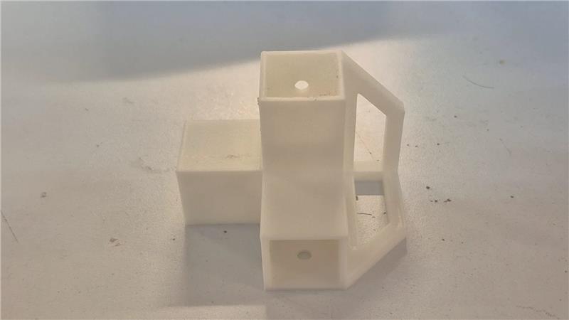
Prototyping and Tolerance Testing: Before spending time and materials printing all the structural components, we first 3D printed a single bottom corner to verify the physical fit with the aluminum extrusions. A tolerance of 0.2 mm was found to be necessary and was applied to all 3D models and subsequent prints.
Mechanical Assembly
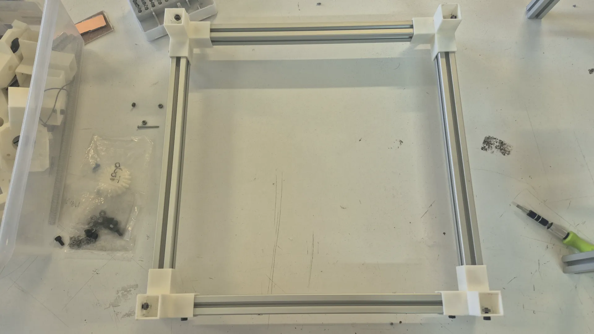
After all the pieces were measured, cutted and 3D printed, the team followed a bottom-up assembly sequence starting with the bottom base frame.
1. First, we carefully measured all the sides formed by the aluminum extrusions to ensure the frame was perfectly square before tightening the 3D printed joints with fasteners.
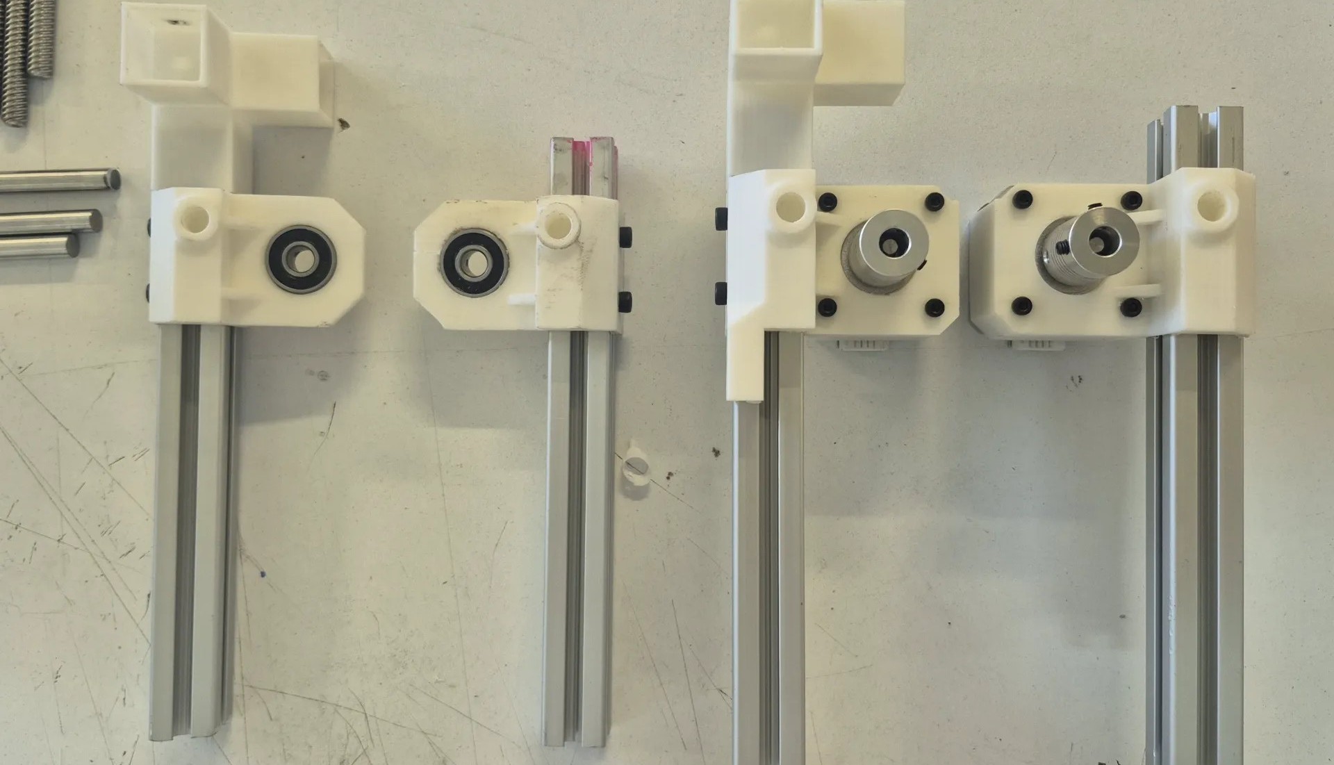
2. Then, we focused on assembling the vertical uprights along with their respective motor mount components.
3. At this stage, we also integrated the sliding carriages and the linear guide rods into the columns. Once these vertical sub-assemblies were ready, we securely fastened them to the bottom base frame.
4. Finally, we constructed the top square frame and bolted it to the columns, completely tying the structure together to achieve maximum rigidity.
During the assembly process, specifically when integrating the X-axis, we noticed that the carriage wobbled and lacked stability with only one support. We realized that adding a second parallel guide was essential to avoid this balance problem. Implementing this crucial modification ensured that the gantry had the rigid and perfectly linear movement necessary for engraving metal without any tool deflection.
As seen in the image, the initial carriage was supported by only a single guide rod and the drive screw. To resolve the wobbling issue, we updated the 3D model by adding a second parallel guide rod, positioning the screw symmetrically in the middle of the two supports.
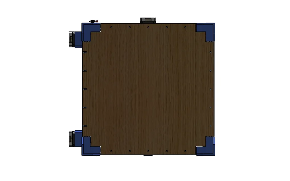
With this problem solved, we set about assembling the bed where the boards would be located. For this, we decided to use MDF and plywood, and we drilled holes to attach it to the profile structure.
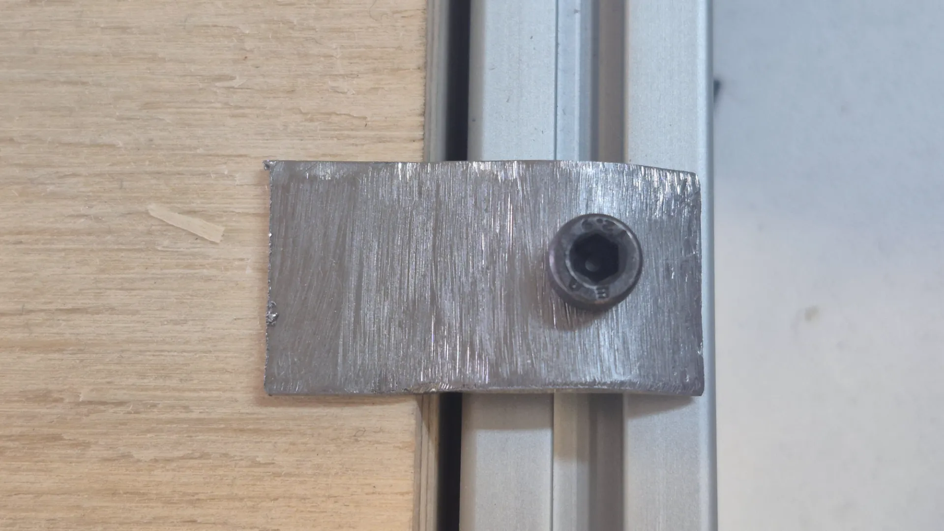
To secure the metal plates to the machine bed, we fabricated custom metal clamps. These clamps were designed to be adjusted using a screw system, providing firm, adjustable pressure that keeps the workpiece perfectly still. Implementing this clamping mechanism was crucial to prevent any movement or vibration during the high-force engraving process, thus ensuring a clean and precise finish on the metal surface.
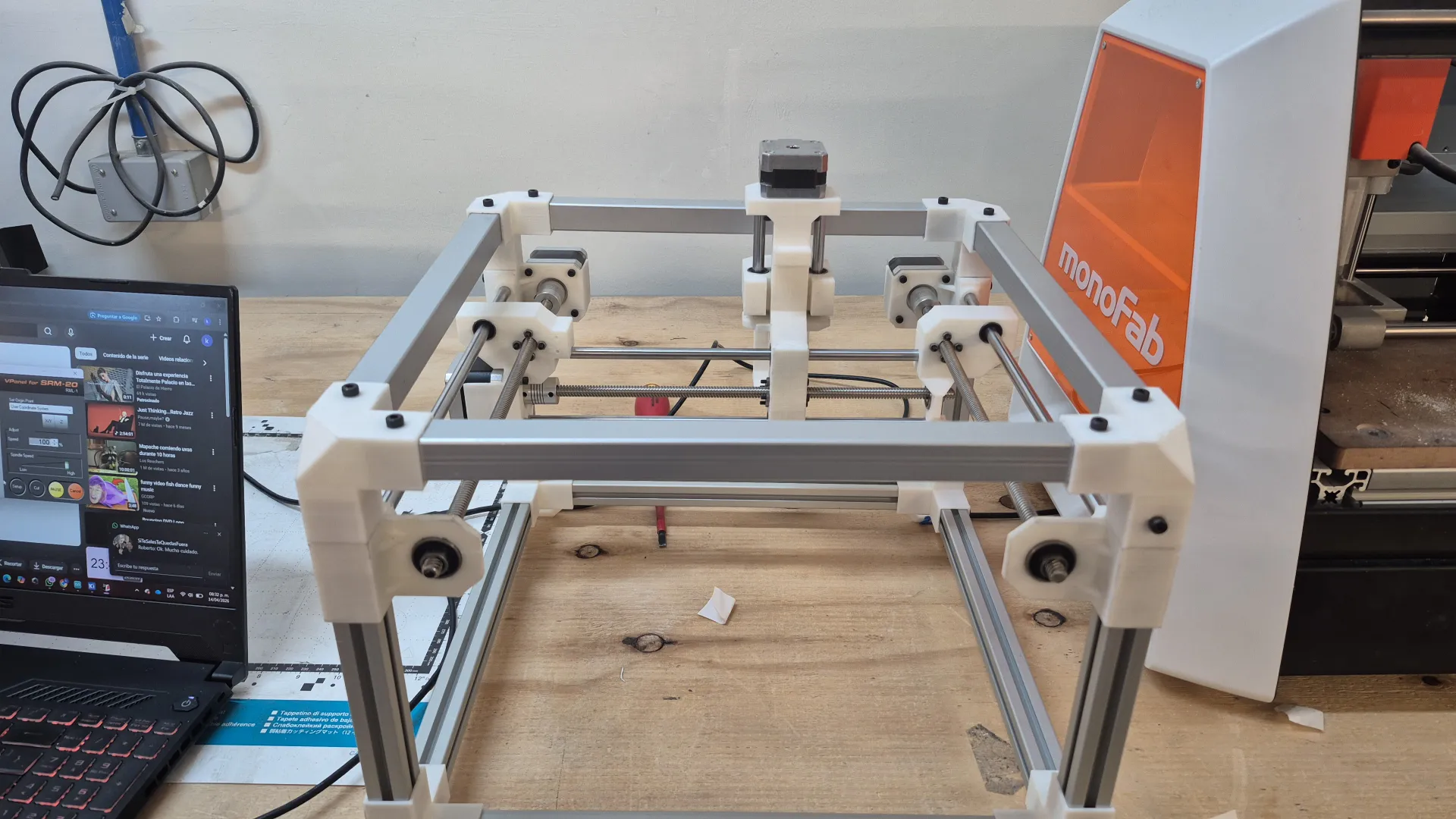
To wrap up the mechanical build, we performed a final pass over the entire structure, securely tightening all the fasteners to guarantee maximum rigidity. Below is the final result of the fully assembled CNC machine:
Enclosure Design
Design and fabrication of a custom CNC enclosure featuring a lift-up door, tool storage drawer, and acrylic windows for visibility.
Enclosure Design
From initial sketches to a fully rendered 3D model, the enclosure was designed to protect the CNC, provide tool storage, and allow clear visibility during operation.
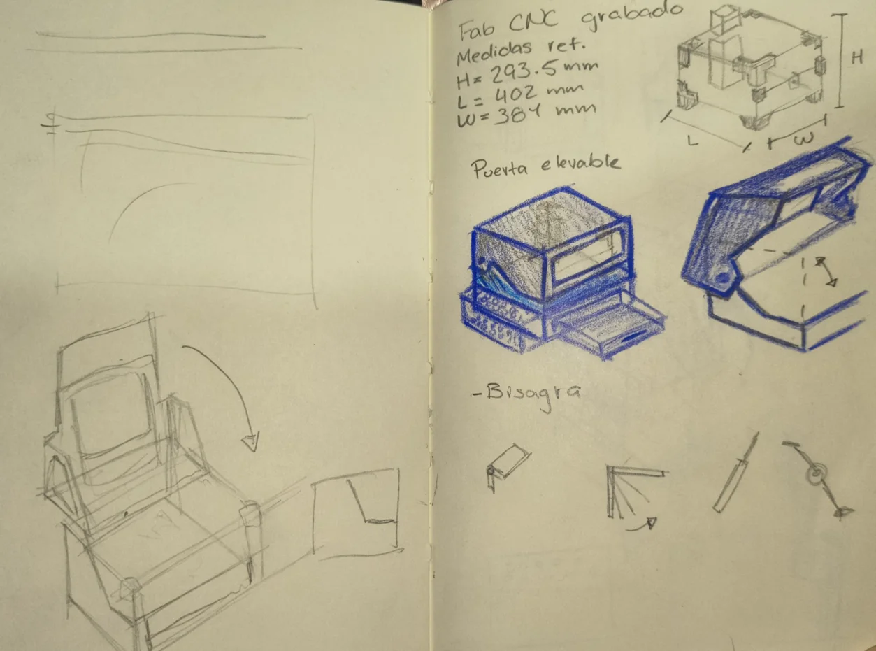
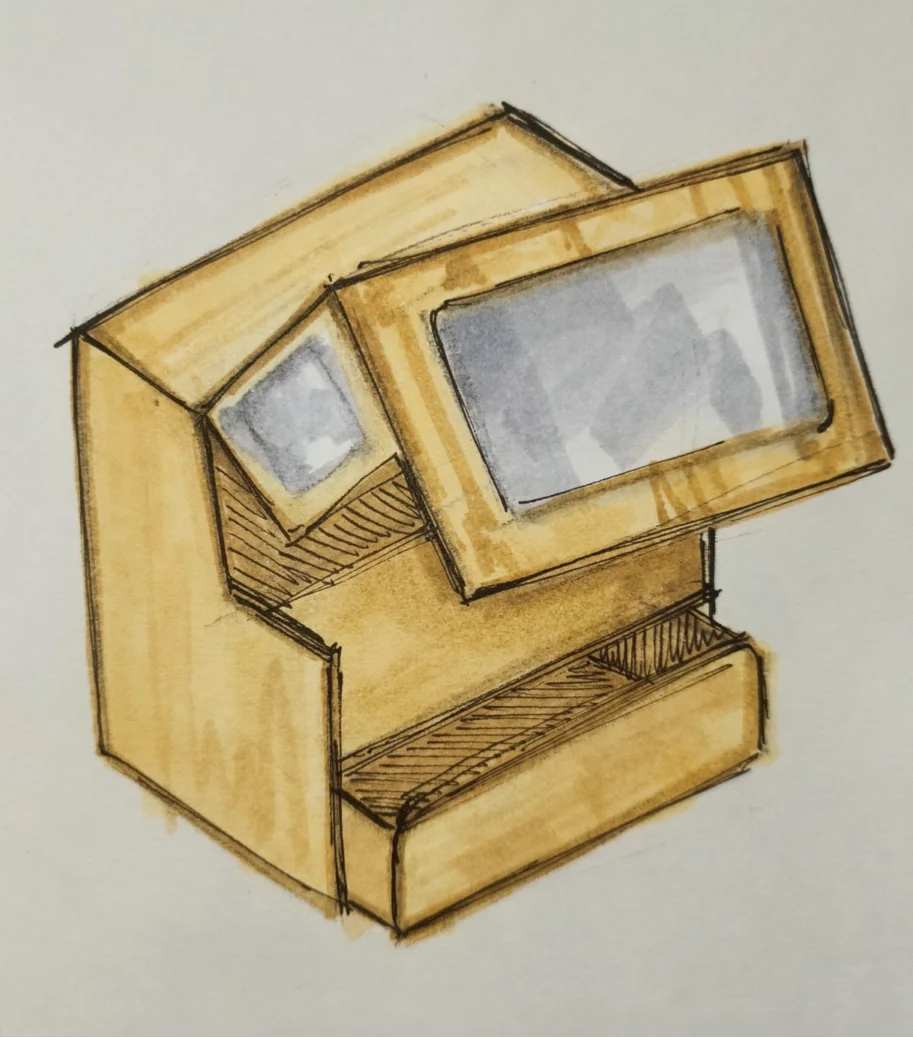
These are the early hand-drawn sketches were we explored the overall shape, proportions, and layout of the enclosure. Thinking about the functional requirements and user experience was key in shaping the initial concepts.
The final concept: a lift-up front door for easy CNC access, a bottom drawer for tool storage, and acrylic windows on the sides and top for visibility during operation.
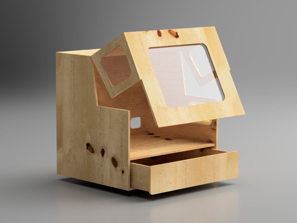
After the concept was finalized, a hybrid design was made in Fusion 360, allowing us to model composite parts and assembling at the same time, enabling precise joinery and accurate cut layouts.
The hybrid modeling workflow made it easy to iterate on part thicknesses and joint tolerances before any material was cut. We made a render to visualize the final design.
Fabrication & Assembly
The enclosure was fabricated using a combination of CNC routing, table saw cuts, and hand finishing, then assembled progressively from the base up.
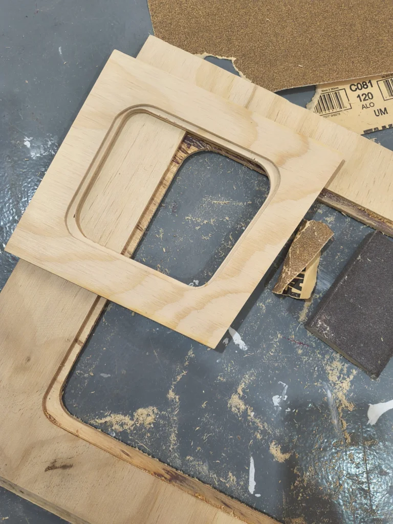
The Fusion 360 design was exported as DXF files and loaded into the CNC software. Parts with pocketing operationswere cut on the CNC router for precision.
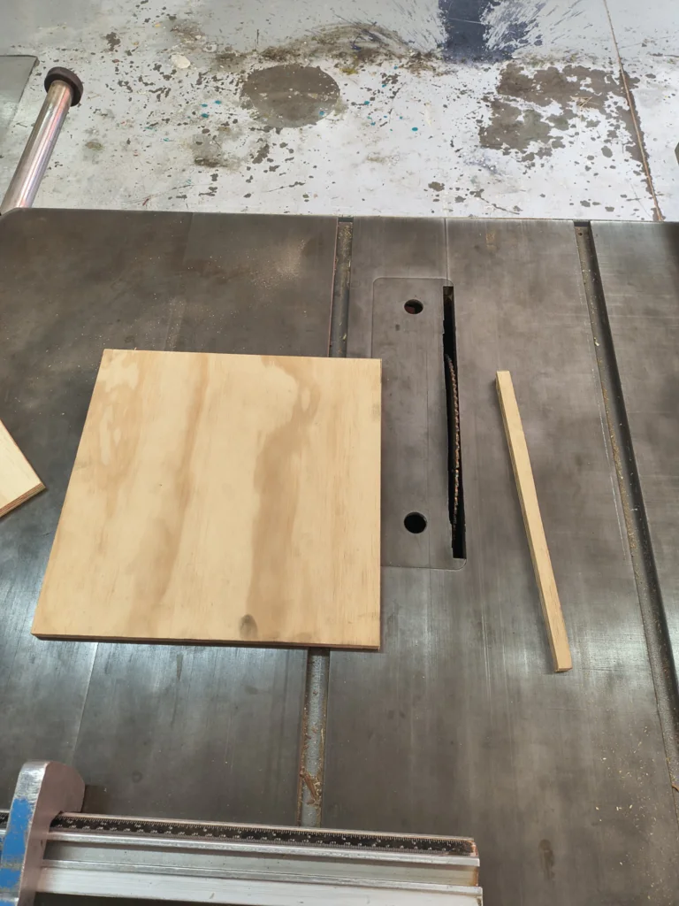
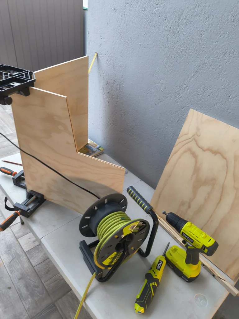
While straight panel cuts and rip cuts were made efficiently on the table saw, speeding up production for parts that did not require CNC pocketing
All panels were sanded with 120-grit sandpaper to remove machine marks, smooth the edges, and ensure a clean glue surface for assembly.
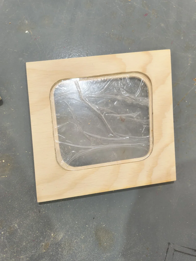
Then the acrylic sheets were laser cutted to size for the enclosure windows, allowing clear visibility into the CNC workspace.
After the acrylic panels were trimmed and test-fit they were glued with clear epoxic adhesive.
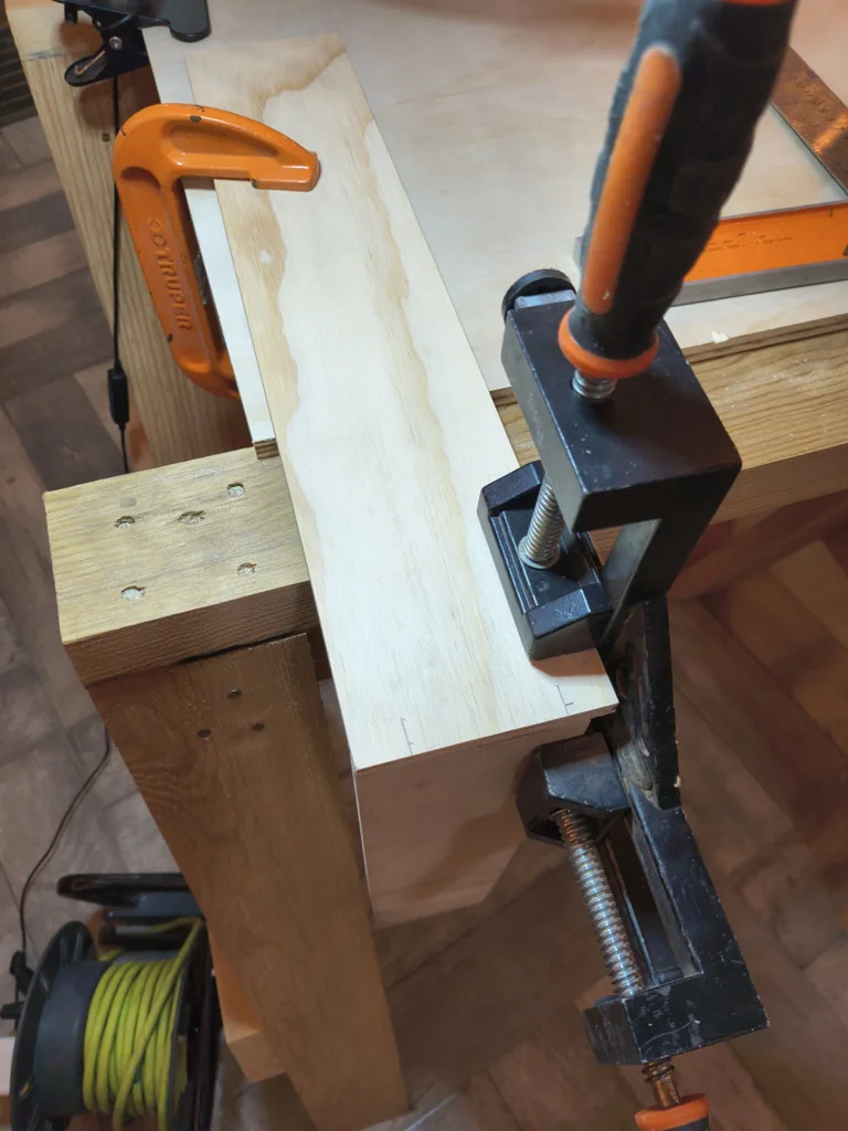
Then the base box was assembled first using corner clamps to hold panels square while the glue set, ensuring a solid and true foundation for the enclosure. It wasfastened with wood screws.
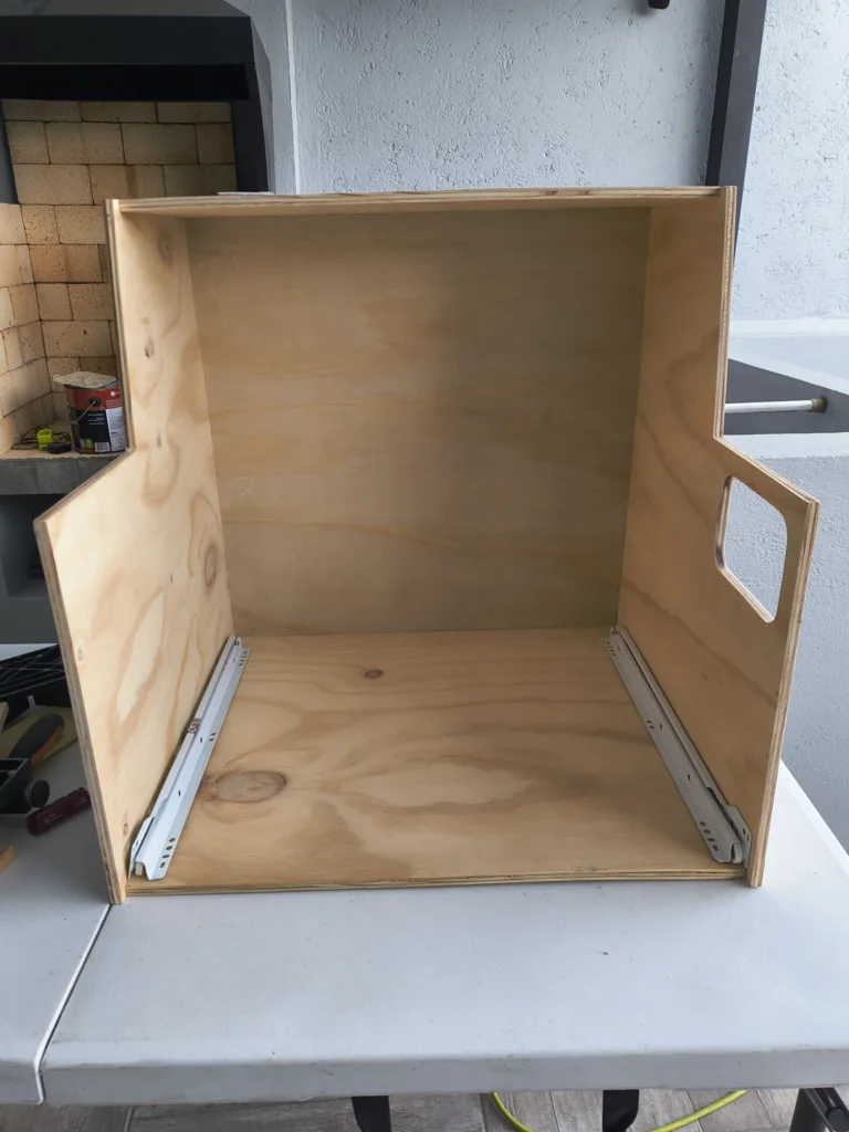
The tool storage drawer box was assembled separately, with the front, back, sides, and bottom glued and clamped together.
After the base part composites were complited, drawer slides (rails) were installed on the inside of the base cabinet and on the drawer box, ensuring smooth and aligned operation.
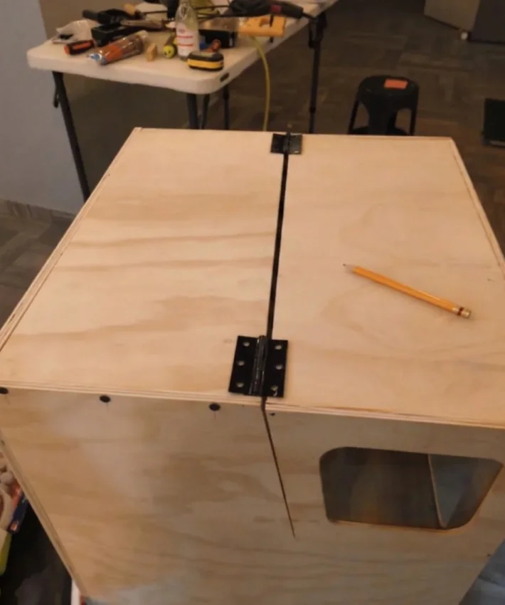
Then hinges were installed along the idth of the lift-up front door, providing even support and smooth operation across the door's span.
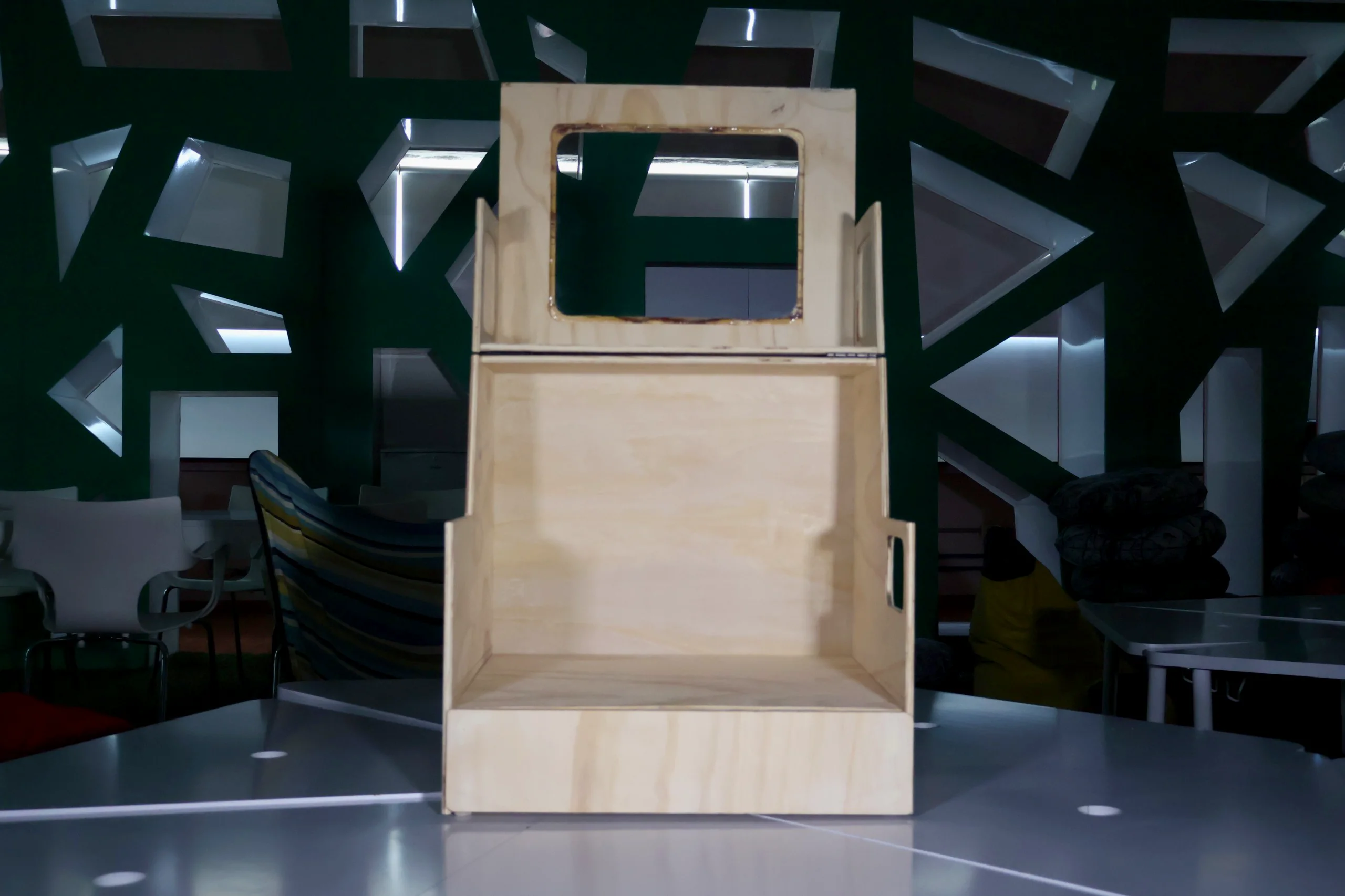
An internal mounting platform was built and installed inside the enclosure to seat the CNC machine at the correct height, with clearance below for cable routing.
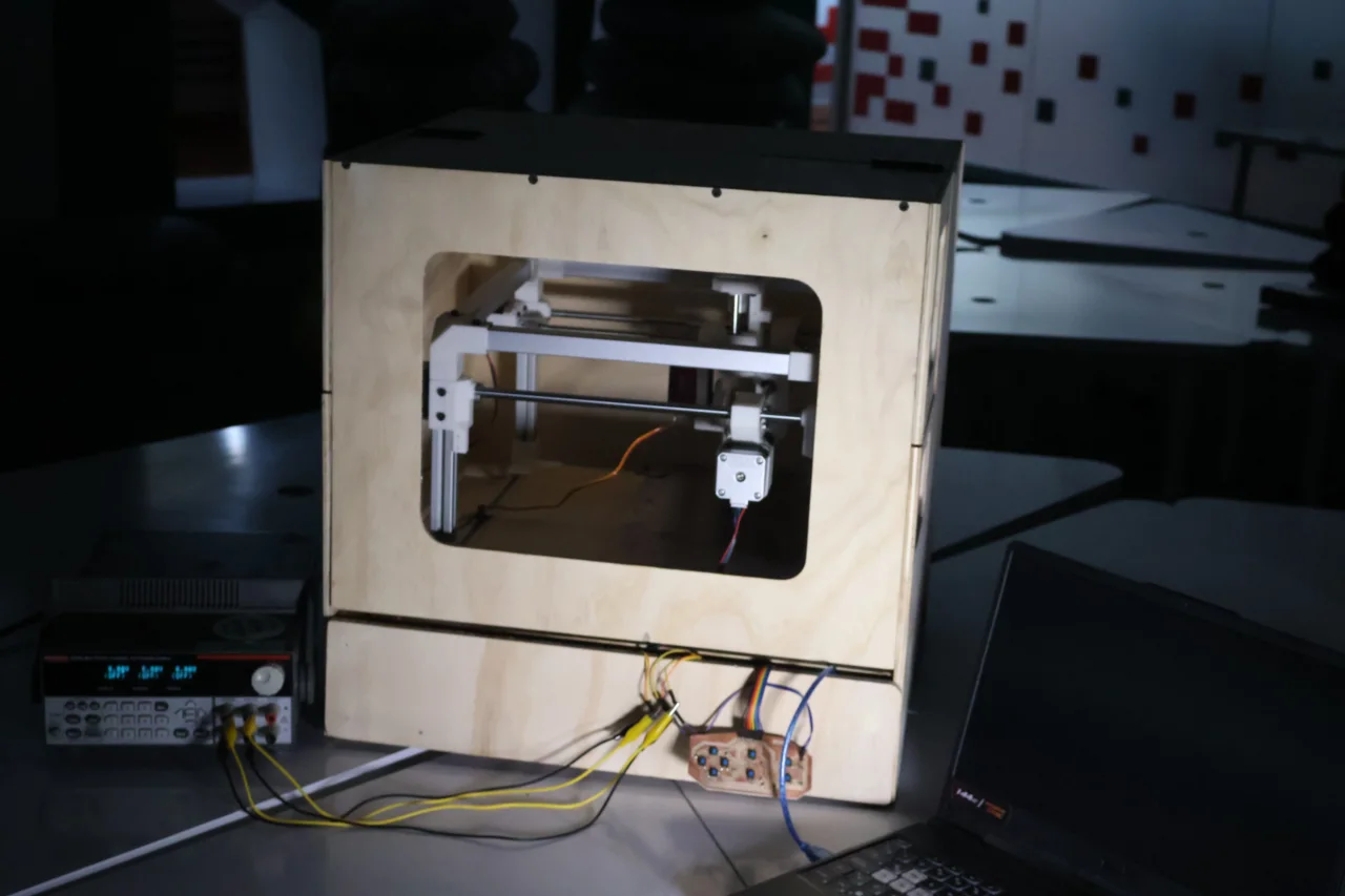
Here is the final result of the enclosure assembly with the CNC machine installed:
Electronics Design
To move the CNC machine, the team designed three custom PCBs that work together as a single electronics system. The first is the microcontroller board, which holds the Raspberry Pi Pico 2 is the brain of the machine. It receives G-code commands from the computer and translates them into electrical pulses that tell each motor when and where to move. It also steps down the 12 V power supply to 3.3 V to safely power the Pico. The second is the driver board, which holds four DRV8825 modules, one per motor. Since the Pico can't power the motors directly, each driver takes the Pico's low-power signal and converts it into the high-current output the NEMA 17 motors actually need. The third is the button board, a small PCB with directional buttons for each axis and two origin-setting buttons, letting the operator manually position the tool and set the starting point before engraving. The microcontroller and driver boards are modular and connect through jumper wires, which made it easy to test and troubleshoot each one independently before integrating the full system.
Electronics theory
Before jumping into the build, here is a brief explanation of the three key components that make the CNC engraver move.
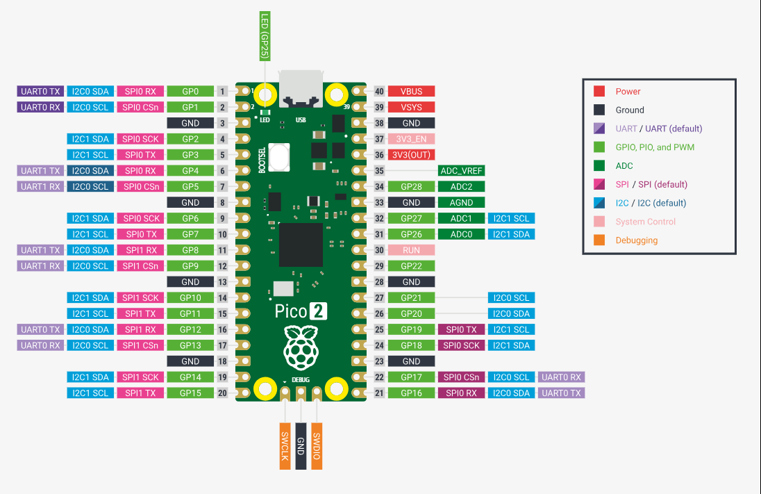
Raspberry Pi Pico 2: the brain
The Pico 2 is a small microcontroller board that reads the G-code instructions (coordinates and speeds) and
sends electrical pulses to each motor telling it exactly how far and in which direction
to move. We chose this board due to its multiple pins, as it allowed us to have all the components connected directly to the microcontroller. It works the same as a Xiao rp2040 or rp2350 the only difference is that this one is a development board and the other was the pure microcontroller which is why it had less pins. Also as we don't need wifi or Bluetooth functions we didn't use a microcontroller with those functions like the esp32.
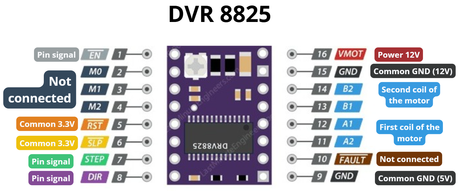
DRV8825: the motor driver
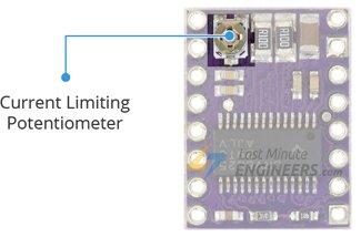
A stepper motor needs much more current than the Pico can safely supply. That is why a DRV8858 modul was used, as it allow us to control stepper motors separating voltages that receives from the microcontroller and the ones that power the motors. It also let us change the current gain with a small potentiometer (a small adjustable screw) which if you turn it clockwise it receives less amperage and if it is turned counterclockwise, it will receive more amperage.
Calculating the potentiometer voltage
Getting the potentiometer value right protects both the driver
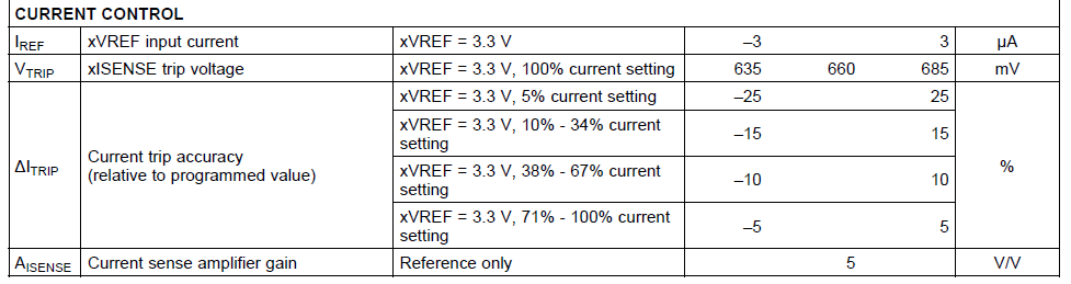
and the motor from burning out. The DRV8825 datasheet provides a formula to find the correct reference voltage
(VREF) for the potentiometer. According to the image, to safely use 100% of the motor's capacity, we should actually set the current to about 71% of the motor's total rated current. This is a common practice to prevent overheating and ensure reliable performance.
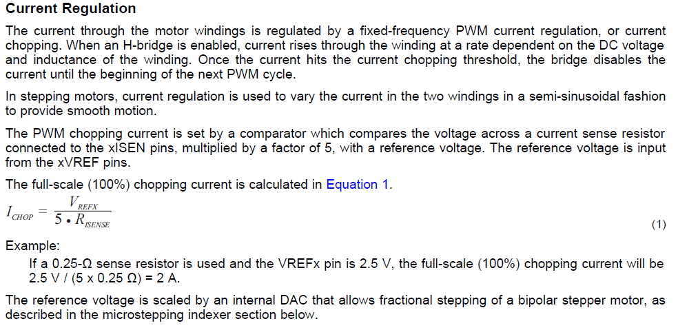
The formula used to calculate the potentiometer setting comes from the datasheet:
ICHOP = VREF / (5 · RSENSE)
ICHOP: The current limit supplied to the motor.
VREF: The reference voltage adjusted with the potentiometer.
RSENSE: A fixed resistor on the board used to measure current.
5: A constant defined by the internal design of the driver.
To find VREF, we first need to know how much current the motors actually demand.
RSENSE is the resistance built into the driver module, which is 0.1 Ω, and
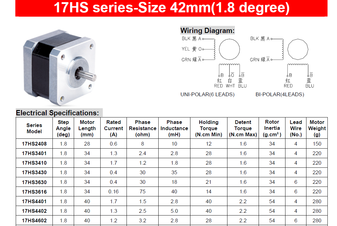
ICHOP is calculated by taking 71% of that rated current (both of which come
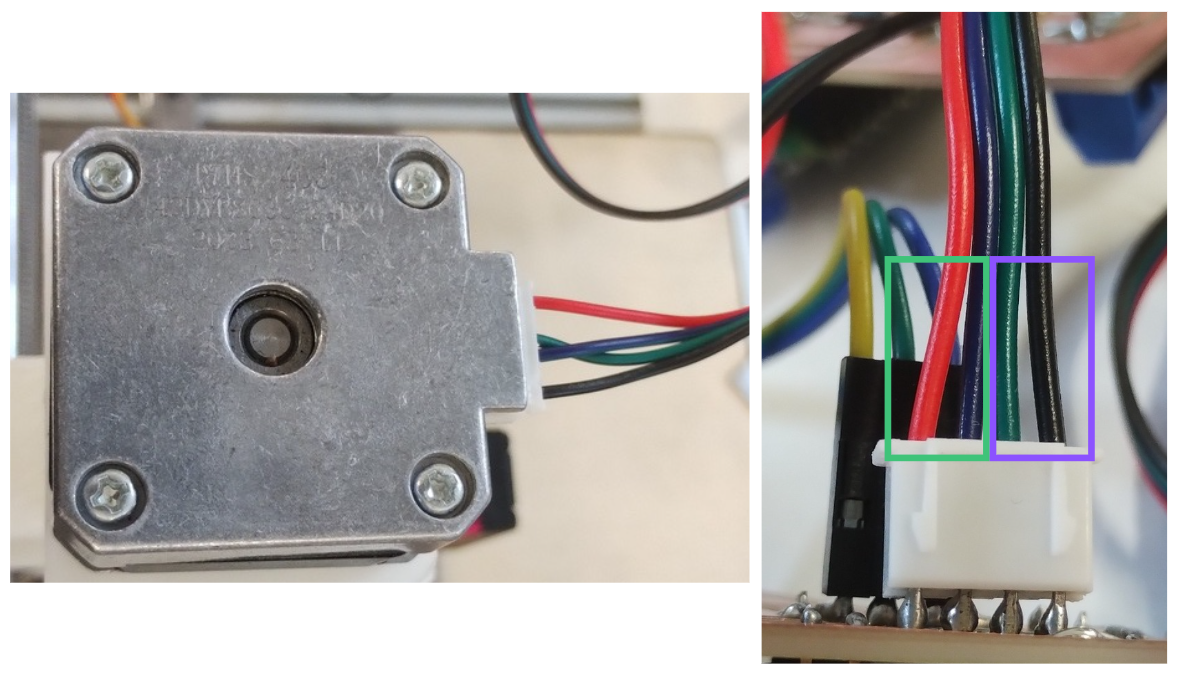
directly from the datasheet of the 17HS4401 stepper motors=.
As shown in the data sheet, the 17HS4401 runs at 1.7 A. So we input that into the formula:
VREF = ICHOP × (RSENSE × 5)
VREF= 1.207 × (0.1 × 5) = 0.595 V
Setting the potentiometer to this value protects both the driver and the motor.
If the voltage is set too low, the motor won't have enough current to move properly.
If it's set too high, the driver receives more current than it can handle and risks
overheating or burning out, and in the worst case, the motor itself can be damaged too.
Note: The potentiometer is adjusted using a small flathead screwdriver.
PCB Design
As mentioned earlier the electronics system consists of three custom PCBs,
all designed in KiCad using the PCM_fab footprint library. The motion control
(motors) is handled by two modular boards: the first holds the
Raspberry Pi Pico 2 and connects to the second via jumper wires through male
pin headers, which contains the DRV8825 drivers that power and control the
stepper motors. Splitting them into two separate boards made the system easier to assemble,
test, and troubleshoot. A third board handles manual control as it carries
directional buttons for the X, Y, and Z axes plus two origin-setting buttons for XY and Z,
replacing the need for limit switches and giving the operator direct hands-on control of the
machine.
The microcontroller board is the brain of the motion system. It houses the
Raspberry Pi Pico 2 and exposes all necessary pins to the driver board
via jumper wires through male pin headers.
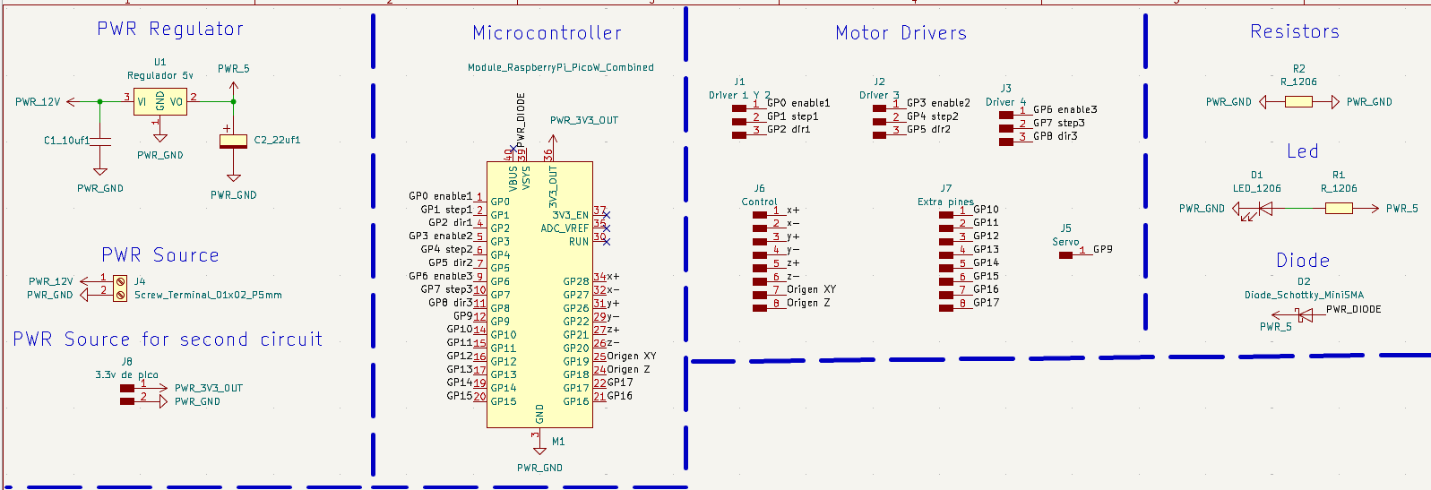
The microcontroller board is divided into four different sections:
Power Supply: Provides 12V power to the board, transforms that voltage to 3.3V to power the Pico without damaging it, and transfers that same 3.3V voltage to the driver board.
Microcontroller: This is where the Raspberry Pi Pico is located, with its corresponding male pins assigned.
Motor Drivers: This section contains the pins for the male pins that the board will use to connect the three pins controlling the motor (STEP, DIR, and ENABLE) via jumpers.
Zero Resistor: Which acts as a bridge between grounds to allow a trace in the design, diode (to prevent backflow and damage), and LED (to confirm that voltage is reaching the board).
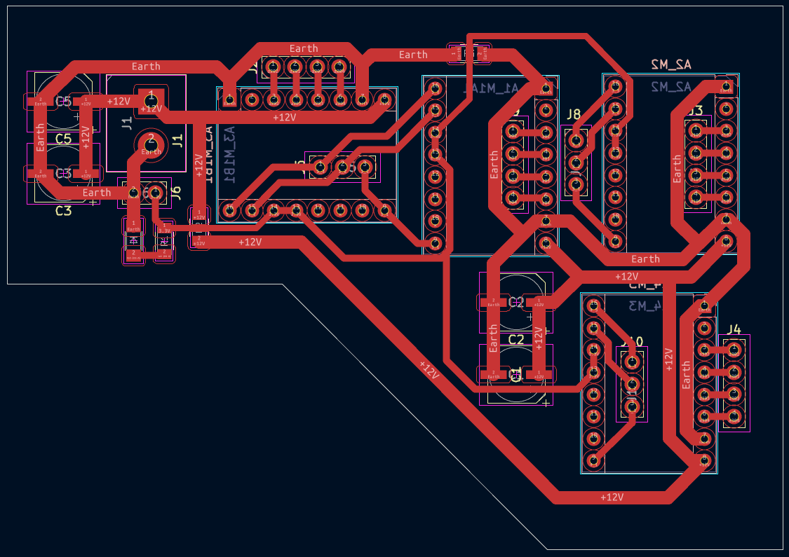
Here is the final microcontroller board schematic design:
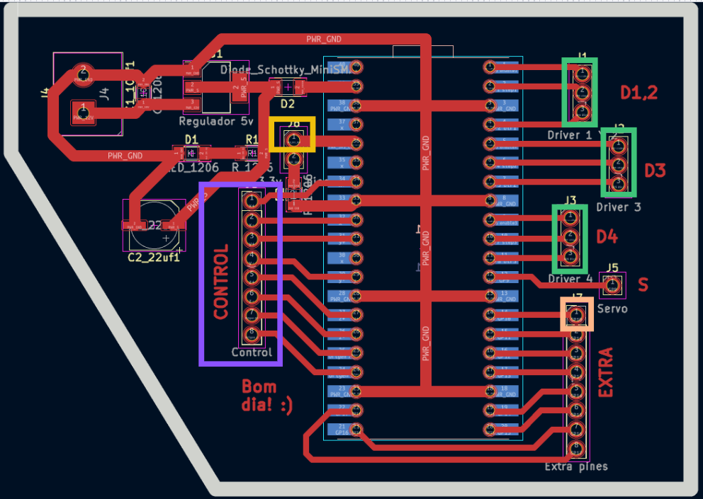
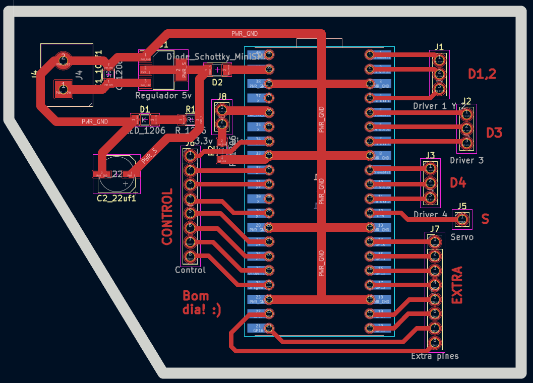
As for the final PCB layout, the pins used were the following:
Controller connection (Purple): Each direction is connected to a signal pin.
Ground (Yellow): Provides a common reference point for the circuit.
Servo motor connection (Cream): Although the servo has its own pin, since it's only a male pin, it was very unstable when soldering. Therefore, we moved it to one of the pins for extra connections.
Motor connection (Green): Connects to the motor driver for control signals.
Board editor
The parameters used for the traces were as follows:
Trace Width (mm)
Power and GND
All other traces
1.5
1.5
0.8
The connected board looked like this:
Note: Zero resistors can help if you're unsure how to connect the traces, however, it's not a good practice.
The drivers used to control the stepper motors are the DRV8825 and the
stepper motors are the NEMA 17.
A third board handles manual control: it carries directional buttons for
the X, Y, and Z axes plus two origin-setting buttons for XY and Z, replacing the need
for limit switches.
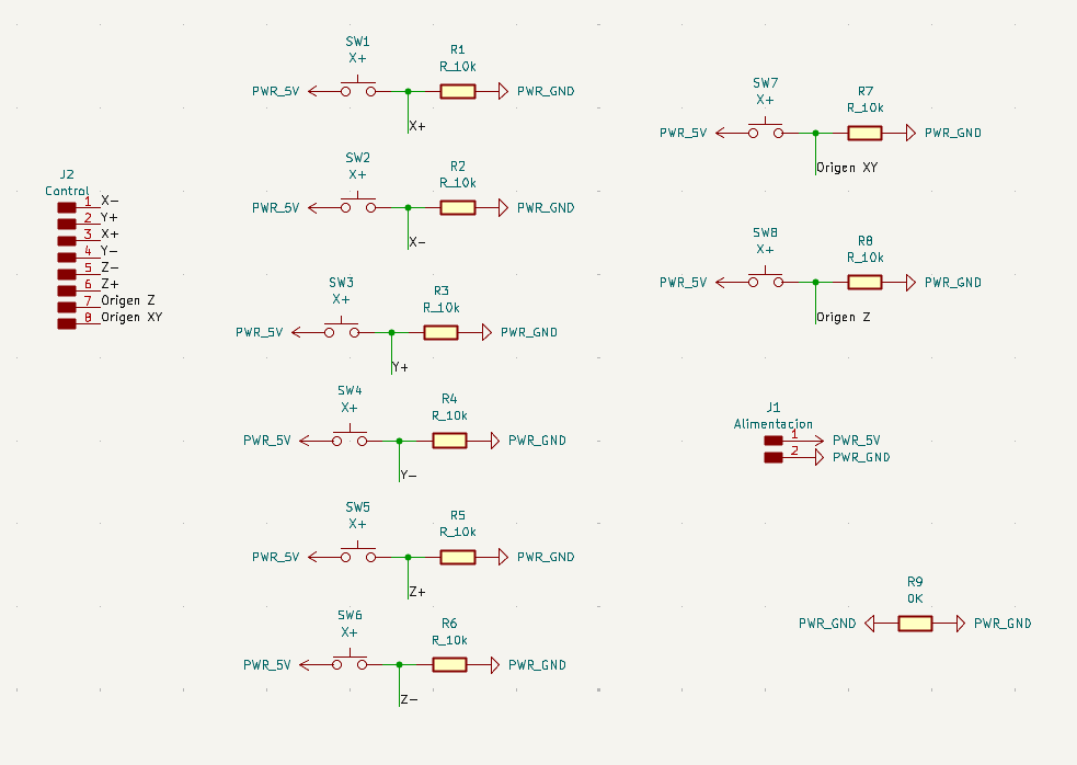
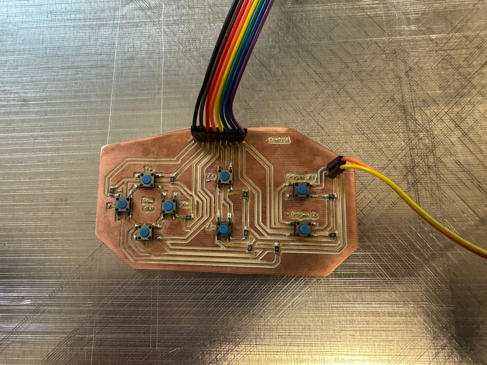
This is the KiCad schematic for a CNC control board. It features 8 push-button switches (SW1–SW8) for axis jogging (X+, X−, Y+, Y−, Z+, Z−) and two homing inputs (Origen XY, Origen Z). Each switch is paired with a 10kΩ pull-up resistor connected to PWR_5V. All signals are routed to an 8-pin connector (J2, labeled "Control"). A 2-pin power input connector (J1, "Alimentacion") provides PWR_5V and PWR_GND, and R9 (0Ω) acts as a jumper.
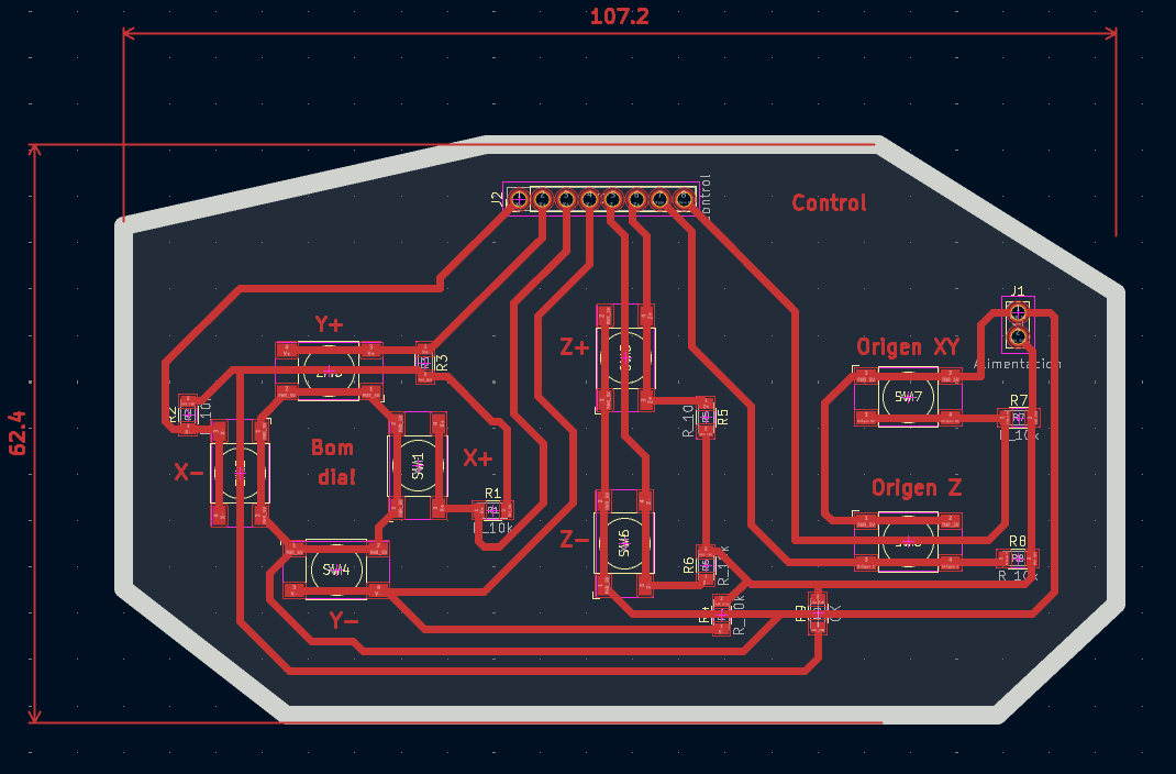
his is the routed PCB layout for the same board, measuring 107.2 × 62.4 mm with an octagonal outline. The switches are distributed across the board and labeled by axis (X+, X−, Y+, Y−, Z+, Z−, Origen XY, Origen Z). The 8-pin control connector (J2) sits at the top center, the power connector (J1) is on the right, and all traces are single-layer routed in red. The layout is compact and follows the spatial logic of a CNC jogging pendant.
Results
Final results of the electronics: the manual control board and the fully integrated system.
The finished manual control board, featuring all axis jogging buttons and homing inputs.
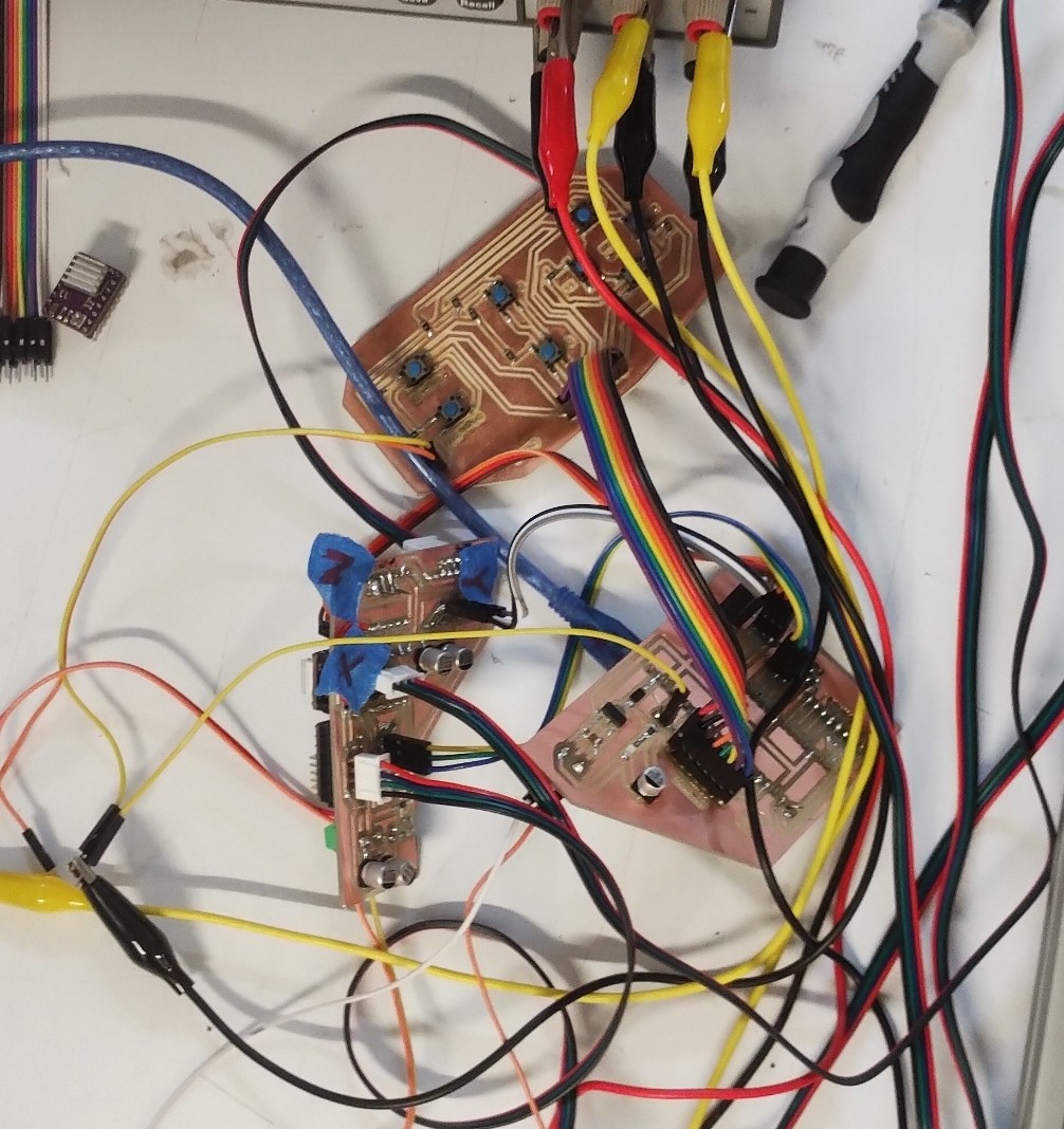
All electronics fully integrated: driver board (left bottom), microcontroller board (right bottom) , and manual control board (center top) connected and operational.
Programming
The CNC machine is programmed in C++ using the Arduino framework on the Raspberry Pi Pico 2. The code handles multi-axis stepper motor control via STEP/DIR/ENABLE signals to the DRV8825 drivers, manual jogging through the button board, and a software-based origin-setting system that replaces traditional limit switches. G-code parsing is used to translate engraving paths into coordinated motor movements.
Development Setup
To start programming, first we defined several parameters and global variables. The following section explains the structure and functionality of the code.
3-Axis CNC Control with Stepper Drivers (DRV8825):
This program controls a 3-axis CNC machine (X, Y, Z) using stepper motors and DRV8825 drivers. Each axis has three main control pins: STEP, DIR, and EN, as well as an endstop switch used for homing. Each STEP pin generates pulses to move the motor, DIR controls the direction, and EN enables or disables the driver. Here is the pin configuration for each axis:
Motion parameters: The variable PASOS_MM defines how many steps are required to move 1 mm. In this case, 800 steps = 1 mm, meaning the system has high precision. For example, if the motor performs 1600 steps, it will move 2 mm.
#define PASOS_MM 800.0
Soft Limits (Safety System): Soft limits define the safe working area of the machine. These values prevent the tool from moving beyond physical boundaries. If the system tries to move outside these limits, the motion will be stopped automatically.
It is important to highlight that these limits must be configured before uploading the program, as they do not represent the real physical limits of the machine. Instead, they are software-defined safety boundaries that must be adjusted according to the actual dimensions and travel range of the CNC system.
Global State Variables: The system uses global variables to track position and motion. These variables are declared as follows:
posX, posY, posZ: current position in steps
dx, dy, dz: movement distance
stepsTotal: total steps of the movement
running: indicates if the machine is moving
softLimitHit: detects safety limit violations
Velocity Control: Velocity is controlled using:
volatile int velMinUs = 2000;
volatile int velMaxUs = 400;
This defines acceleration and deceleration behavior.
Step Pulse Function: The function stepPulse() generates a pulse signal required to move a stepper motor one step.
Limit Validation Function: The function dentroLimites() checks if a movement is within safe boundaries.
 bool dentroLimites(float x, float y, float z) {

  if (x < X_MIN || x > X_MAX) return false;
  if (y < Y_MIN || y > Y_MAX) return false;
  if (z < Z_MIN || z > Z_MAX) return false;

  return true;
}
Stepper Control ISR (Core Logic): The function stepperISR() is the core of the motion system. It runs repeatedly using a timer and controls all three axes simultaneously. It implements:
Acceleration and deceleration using a smooth curve
Multi-axis synchronized motion
Real-time soft limit checking
Velocity is dynamically adjusted using this formula:
This creates a smooth start and stop (S-curve motion).
The system also uses error accumulation (errX, errY, errZ) to synchronize movement across axes, similar to a Bresenham algorithm.
Movement Function (Steps):
The function moverXYZ() moves the motors based on step values.
Each axis is calibrated independently using homingEje().
Setup Function: In setup(), we configure all pins, enable the drivers, and initialize serial communication. Finally, the system performs homing:
homingXYZ();
This ensures the machine starts from a known reference position.
Main Loop: Inside the loop(), the system:
Checks for soft limit errors
Executes a movement if the machine is idle
moverXYZmm(10, 5, 2);
This command moves the machine 10 mm in X, 5 mm in Y, and 2 mm in Z. After completing the motion, it prints the new position and waits 3 seconds before repeating.
CNC Desk Test Step-by-step Analysis
Before running the code on the machine, we performed a desk test to verify that the motion logic works correctly. The following cases analyze how our system interprets and executes movement commands, including limit validation and direction handling.
Movement performed by moverXYZmm(10, 5, 2);
📌 Case study
We call moverXYZmm(10, 5, 2), which converts millimeters to steps and passes them to moverXYZ(). With 800 steps/mm, the resulting call is:
moverXYZ(8000, 4000, 1600)
// X = 8000 steps
// Y = 4000 steps
// Z = 1600 steps
// Total steps: 8000
The axis with the most steps (X = 8000) sets the total, and the other axes are distributed proportionally using error accumulation.
🔁 Step-by-step iterations
Each iteration, our algorithm accumulates error per axis. When the error exceeds the threshold, a step pulse is generated. This keeps all axes synchronized throughout the movement:
Iteration
X
Y
Z
1
✔️
❌
❌
2
✔️
✔️
❌
3
✔️
❌
❌
4
✔️
✔️
❌
5
✔️
❌
✔️
X moves every iteration · Y every 2 · Z every 5 Ratio: 1 : 0.5 : 0.2 → Perfect linear 3D movement ✔️
🎯 Final result: X = 10 mm · Y = 5 mm · Z = 2 mm
📌 Case study negative movement
We test what happens when we command a movement that would take the machine outside its safe working area:
❌ Our limit validation function dentroLimites() detects the violation immediately and cancels the motion before any pulses are sent to the drivers.
⚙️ Behavior without limits (analysis)
To understand the underlying logic, we analyzed what moverXYZ() would do if limits did not exist. The system would correctly compute magnitudes and directions:
moverXYZ(-16000, -8000, 1600)
// dx=16000, dy=8000, dz=1600
// X → LOW (negative)
// Y → LOW (negative)
// Z → HIGH (positive)
✔️ Our system correctly separates magnitude (abs()) from direction (DIR pin), so negative movements are fully supported at the hardware level.
Conclusion: the algorithm handles negative movements correctly, but our soft limits protect the machine from leaving its safe boundaries. Once we verified the desk test, we proceeded to run the code on the actual machine with our teammates.
CAM Software DXF/SVG to G-code
After testing the CNC machine some changes were made, such as removing the endstops. In parallel, we developed the CAM software that allows us to convert DXF and SVG files into G-code format. This software is also responsible for communicating directly with the machine firmware, which executes the movements.
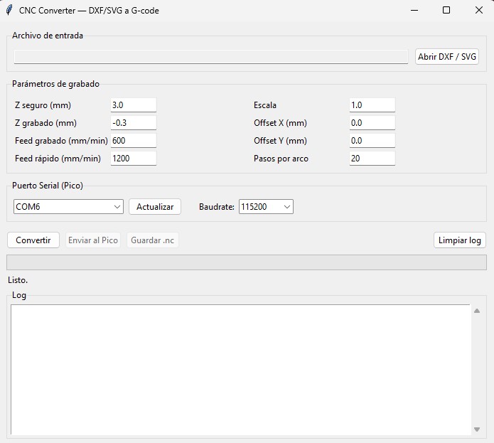
CAM software interface we can convert from DXF to G-code and from SVG to G-code. From this program we can send the generated G-code directly to the microcontroller, as well as save the G-code file.
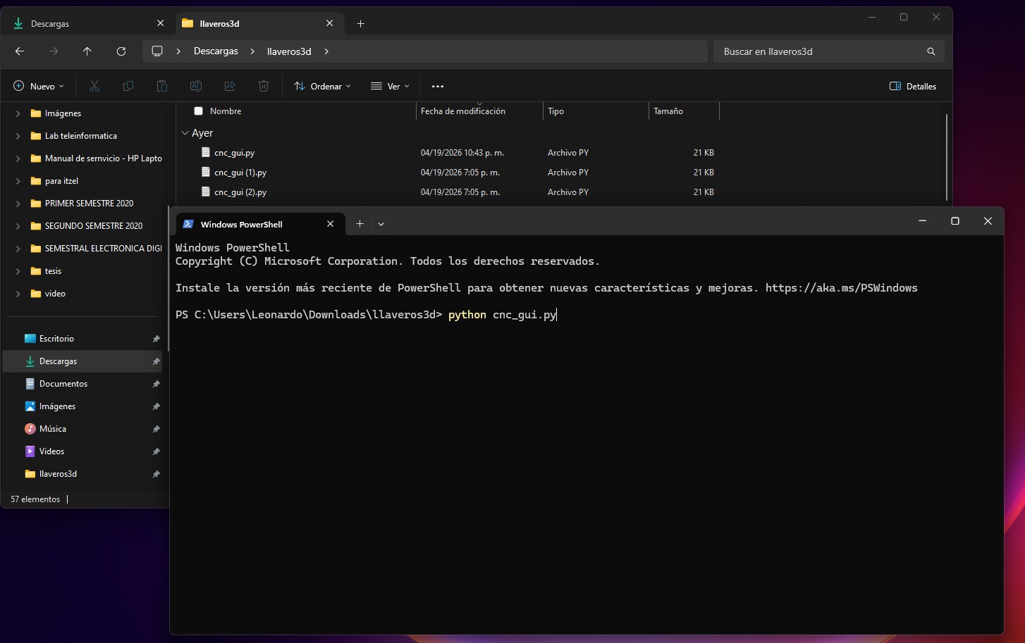
To run this program, we open it from the Windows CMD (terminal). The application starts by initializing the GUI and waits for user interaction.
CAM software demo video showing the full conversion and sending workflow from file selection to G-code transmission.
Default Configuration Parameters these predefined values control machining behavior. z_seguro keeps the tool lifted when not cutting, z_grabado sets the cutting depth, feed_rapido and feed_grabado control travel and cutting speeds, and arco_pasos sets the resolution of curves.
G-code Generation GcodeWriter class manages tool position, tool state, and generated G-code lines. At startup, the CNC is configured with standard commands and the tool is moved to a safe height. G0 is used for rapid travel and G1 for cutting moves.
G28   ; go to home position
G21   ; set units to millimeters
G0 Z3 ; move to safe height

// Movements:
G0 X10 Y10      ; rapid (no cutting)
G1 X20 Y20 F600 ; cutting move
Supported entities and serial communication the converter handles all common DXF and SVG geometry. Curves are approximated as small line segments since our firmware does not support G2/G3. Each G-code line is sent one at a time and the program waits for an ok response before continuing. If an error is detected, the tool is lifted automatically to prevent damage.
// DXF: LINE, POLYLINE,
//      CIRCLE, ARC, SPLINE
// SVG: lines and curves
//      (approximated as segments)

// Serial communication:
ser.write((linea + "\n").encode())
respuesta = ser.readline().decode()
// waits "ok" before next line

// On error → tool lift:
G0 Z5
Libraries used the application is built entirely in Python. ezdxf handles DXF parsing, svgpathtools reads SVG paths, and tkinter provides the graphical interface. threading keeps the UI responsive during long conversions or transmissions.
import ezdxf
from svgpathtools import svg2paths
from tkinter import ttk, filedialog,
  messagebox, scrolledtext
import threading
import os, sys, math, time
After testing with our team, several changes were made: endstops were removed and the machine origin is now set manually using buttons. The X axis uses two synchronized stepper motors. This program combines real-time manual jog control with buffered G-code execution.
Pin Configuration Dual X Motor the X axis is driven by two synchronized motors (X1 and X2) that always step together. Y and Z each use a single motor.
Manual Control (Buttons) jog moves the selected axis while the button is held. The origin buttons set the current position as (0,0,0) for XY and Z independently, replacing the need for endstop switches.
Motion Parameters & Soft Limits 800 steps/mm gives our system high precision. Velocity is defined by a min/max range in microseconds to create smooth acceleration and deceleration. Soft limits define the safe working area and stop motion if exceeded.
#define PASOS_MM     800.0
#define VEL_MIN_US   2000
#define VEL_MAX_US    400
#define JOG_DELAY_US  600

// Safe working area:
X: 0.0 – 220.0 mm
Y: 0.0 – 200.0 mm
Z: -10.0 – 5.0 mm
Buffer System (G-code) incoming G-code commands are stored in a circular queue before execution. This allows smooth and continuous motion without pausing to wait for the next serial command.
Step Pulse Both X motors fire simultaneously to keep the gantry square, both X drivers always receive their pulse at exactly the same time in a single function call.
Servo Control adjusts tool orientation based on movement direction. The angle is calculated with atan2() and updated gradually to avoid abrupt rotations. It is only active during G1 cutting moves; during G0 rapid travel the servo remains inactive.
G-code Interpreter our firmware accepts a standard subset of G-code. Every valid command responds with ok so the CAM software knows when to send the next line.
G0  → fast movement (no cutting)
G1  → cutting (activates servo)
G21 → set units to millimeters
G28 → reset position (home)
G92 → define current position
M114 → report position
M280 → control servo manually
Main Loop each iteration of loop() checks buttons for manual jog, reads incoming G-code from the serial port, executes the next buffered movement, and updates the servo angle smoothly.
void loop() {
  leerBotones();      // manual jog
  leerGcodeSerial();  // from PC
  ejecutarBuffer();   // queued moves
  actualizarServo();  // smooth angle
}
This week was a complete end-to-end engineering challenge. We had to design, fabricate, wire, and program a working machine as a team, where every discipline depended on the others. The experience pushed us to think beyond our individual roles and understand the project as a whole.
Systems thinking is essential: Building a machine means every decision influences everything else. Mechanical dimensions, electronics pinouts, firmware logic, and enclosure layout all need to be considered together as one interconnected system.
Iteration is the actual workflow: Hardware development naturally involves multiple rounds of testing and refinement. Embracing this process and planning time for it leads to better and more reliable results.
Adaptability is a strength: Mid-project changes are a normal part of any build. Being able to pivot and find a working solution without losing momentum is one of the most valuable skills a team can develop.
Owning your tools gives you real control: When you build or customize your own software and electronics, you can adapt them exactly to what the project needs, making the development process faster and more flexible.
Full system testing is key: Testing individual parts is important, but integration always reveals new opportunities for improvement. Bringing all subsystems together early helps the team identify and solve those challenges with more time to spare.
If a second version is ever made, we would like to expand the variety and complexity of the engraving paths the machine can produce, and design a dedicated housing to integrate all the electronics cleanly into the enclosure so the full system feels like a finished, unified product.