Mechanical Design, Machine Design
For week 12 of Fab Academy, my team and I decided to build a custom CNC machine designed to engrave screen-printed stamps onto metal plates.
Group Machine CNC
Within the collaborative project, my primary responsibility was the design and fabrication of the machine's mechanical system. Since metal engraving and scratching require considerable cutting force, I designed the motion transmission system using ball screws to ensure the necessary mechanical advantage and thrust. To achieve the required structural rigidity while maintaining the build's modularity, I constructed the main frame using aluminum extrusion profiles combined with custom 3D-printed joints and supports.
CAD Design
In the following carousel, I have arranged images of the main components that I designed and manufactured for the mechanical system.
Gear
To complete the tangential control mechanism, I assembled a custom 90-degree bevel gear transmission.
- Gear Type: Bevel Gears 90-degree
- Module: 2
- Driving Gear (Servo): 20 Teeth
- Driven Pinion (Tool): 18 Teeth
Complete Assembly
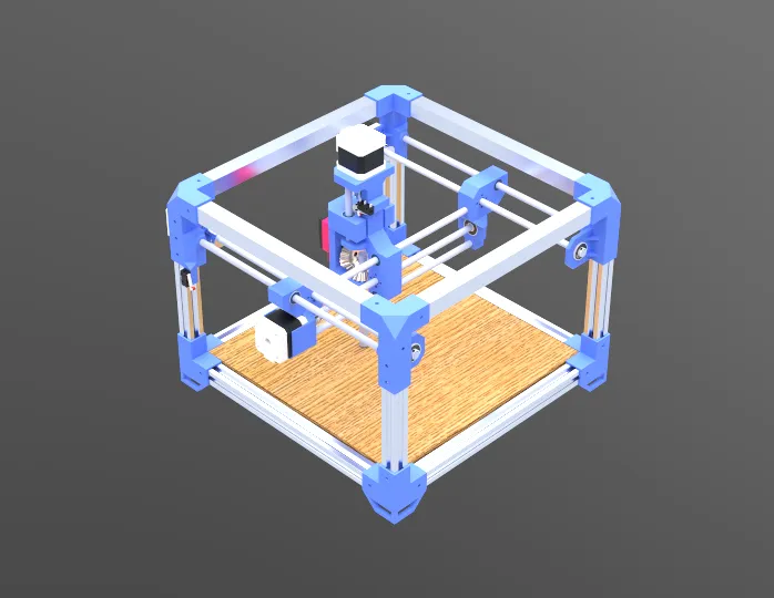
Once all the individual components were designed, I created a complete 3D assembly of the entire CNC machine. This step allowed me to check the overall alignment, make sure all the parts fit together perfectly, and check for physical interference between the moving axles. By visualizing the completed mechanism in the software, I was able to confidently determine if any final design modifications were necessary before moving forward with 3D printing and physical fabrication.
Prototyping and Tolerance Testing
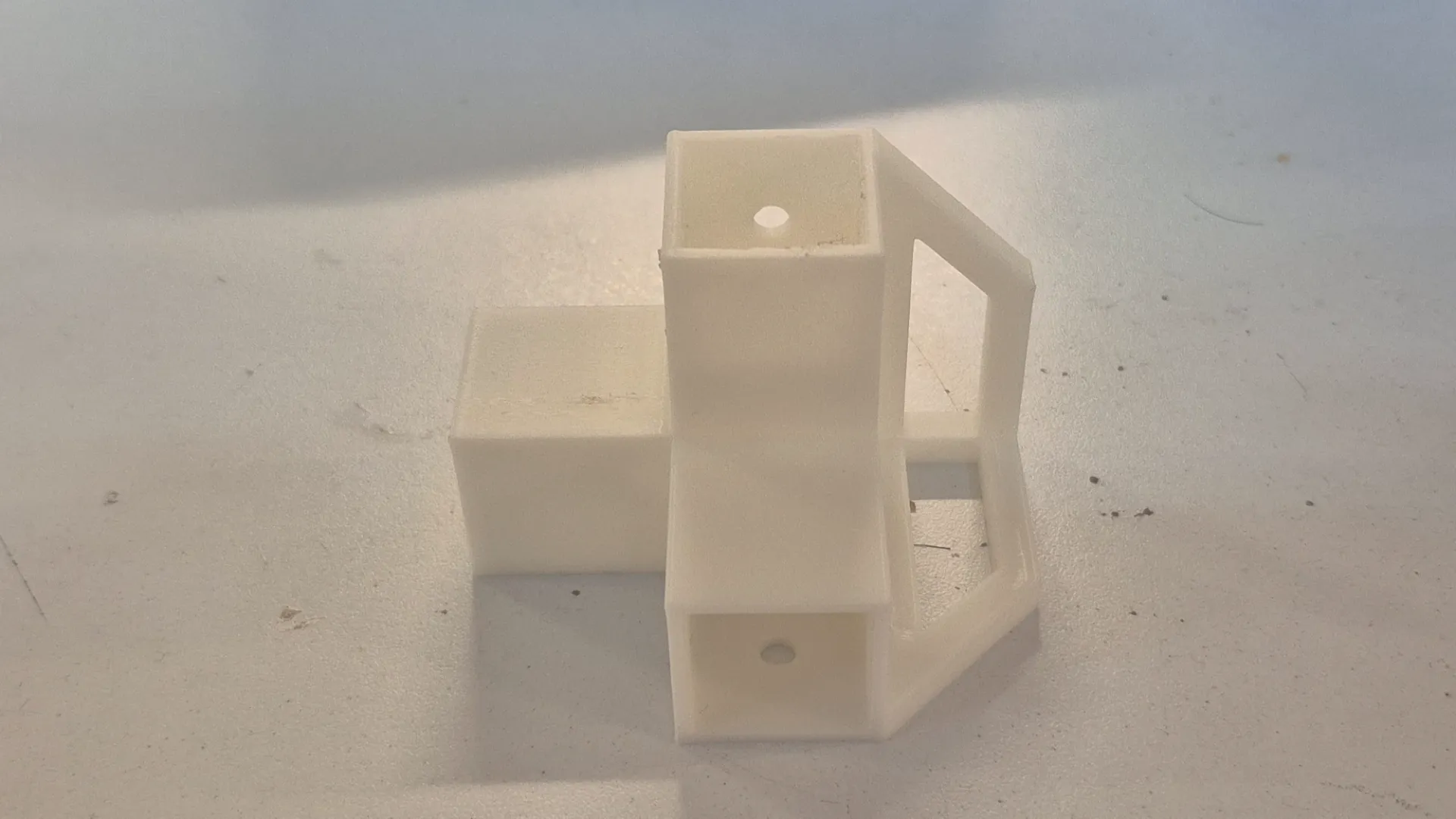
Before spending time and materials printing all the structural components, I first 3D printed a single bottom corner joint to serve as a test piece. It was crucial to physically verify its functionality and check the actual tolerances with the aluminum extrusions. Once I tested the fit, I realized it was necessary to set a tolerance of 0.2 mm, so I modified the 3D models to implement this change. With the updated designs ready, I proceeded to print all the remaining parts.
Assembling the CNC
To keep the project organized and replicable, I compiled a comprehensive Bill of Materials. It is divided into off-the-shelf components that were purchased and custom parts that were fabricated in the lab.
Purchased Components (Off-the-shelf)
| Qty | Component | Description / Specs |
|---|---|---|
| 4 | NEMA Stepper Motors | For X, Y, and Z axis movement |
| 4 | Flexible Couplers | Connects NEMA motor shafts to the lead screws |
| 8 | Aluminum Extrusion Profiles | Main structural frame. Cut lengths: 4x 300 mm and 4x 190 mm |
| 4 | Square Tubing | Additional structural support. Cut lengths: 4x 300 mm |
| 6 | Linear Guide Rods | Smooth steel rods. Cut lengths: 2x 305 mm, 1x 292 mm, 1x 260 mm, and 2x 87 mm |
| 4 | Lead Screws | Threaded rods for motion. Cut lengths: 2x 320 mm, 1x 272 mm, and 1x 75 mm |
| 4 | Brass Lead Screw Nuts | Couples the carriage to the lead screw |
| 6 | Linear Bearings | For smooth travel along the guide rods |
| 4 | Mounted Bearings with Set Screws | To securely hold the ends of the lead screws |
| 32 | M4 x 6mm Screws | Fasteners |
| 20 | M4 x 10mm Screws | Fasteners |
| 12 | M3 x 8mm Screws | Fasteners |
| 8 | M3 x 16mm Screws | Fasteners |
| 16 | M3 x 30mm Screws | Fasteners |
| # | Respective nuts for each screw | Fasteners |
Fabricated Components
| Qty | Component | Process / Material |
|---|---|---|
| 1 Set | Custom Joints, and Motor Mounts | 3D Printed (PLA) |
| 1 Set | X, Y, and Z Axis Carriages | 3D Printed (PLA) |
| 1 | Machine Bed | Cut MDF & Plywood |
| 4 | Workholding Clamps | Fabricated Metal |
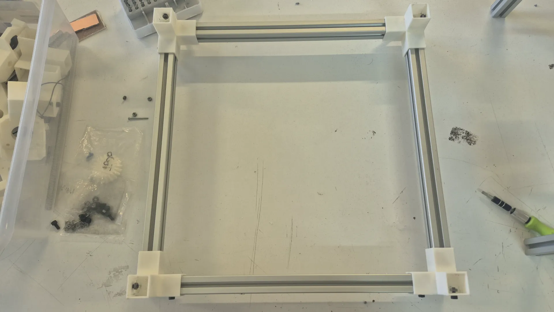
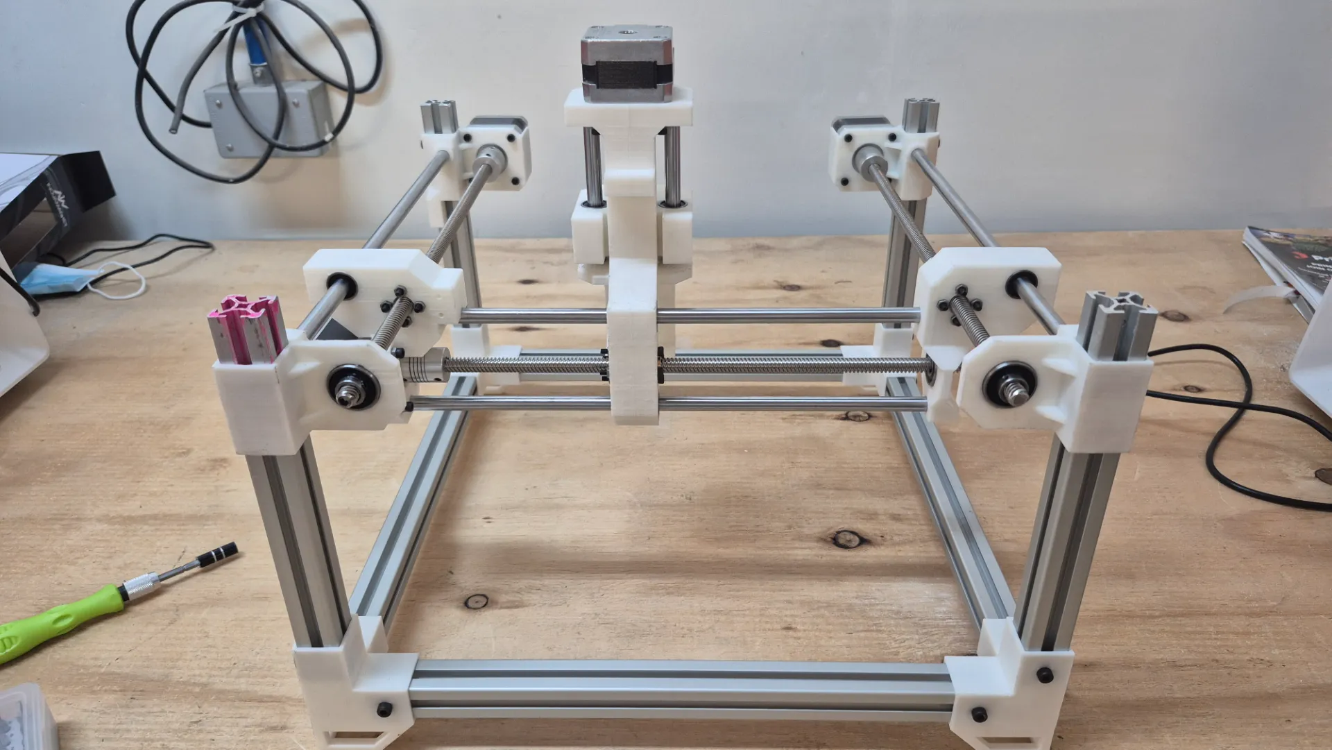
- I began the physical assembly from the ground up, starting with the bottom base frame. I carefully measured all the sides formed by the aluminum extrusions to ensure the base was perfectly square and true.
- Next, I focused on assembling the vertical uprights along with their respective motor mount components.
- At this stage, I also integrated the sliding carriages and the linear guide rods into the columns.
- Once these vertical sub-assemblies were ready, I securely fastened them to the bottom base frame.
- Finally, I constructed the top square frame and bolted it to the columns, completely tying the structure together to achieve maximum rigidity.
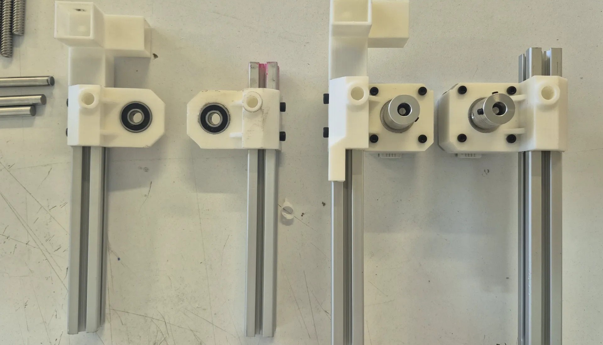
During the assembly process, specifically when integrating the X-axis, I noticed that the carriage wobbled and lacked stability with only one support. I realized that adding a second parallel guide was essential to avoid this balance problem. Implementing this crucial modification ensured that the gantry had the rigid and perfectly linear movement necessary for engraving metal without any tool deflection.
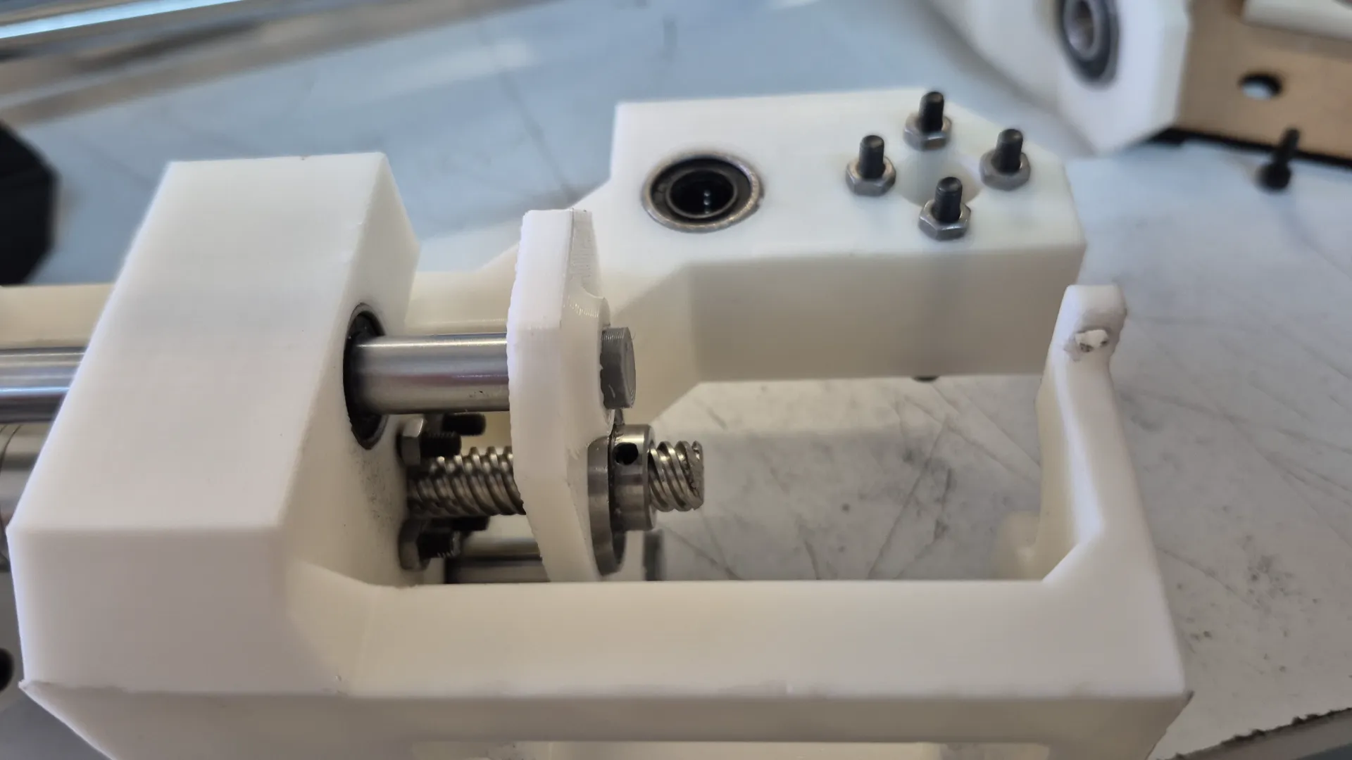
As seen in the image, the initial carriage was supported by only a single guide rod and the drive screw. To resolve the wobbling issue, I updated the 3D model by adding a second parallel guide rod, positioning the screw symmetrically in the middle of the two supports.
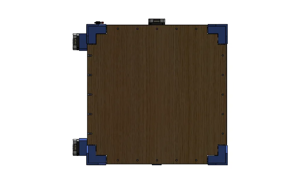
With this problem solved, I set about assembling the bed where the boards would be located. For this, I decided to use MDF and plywood, and I drilled holes to attach it to the profile structure.
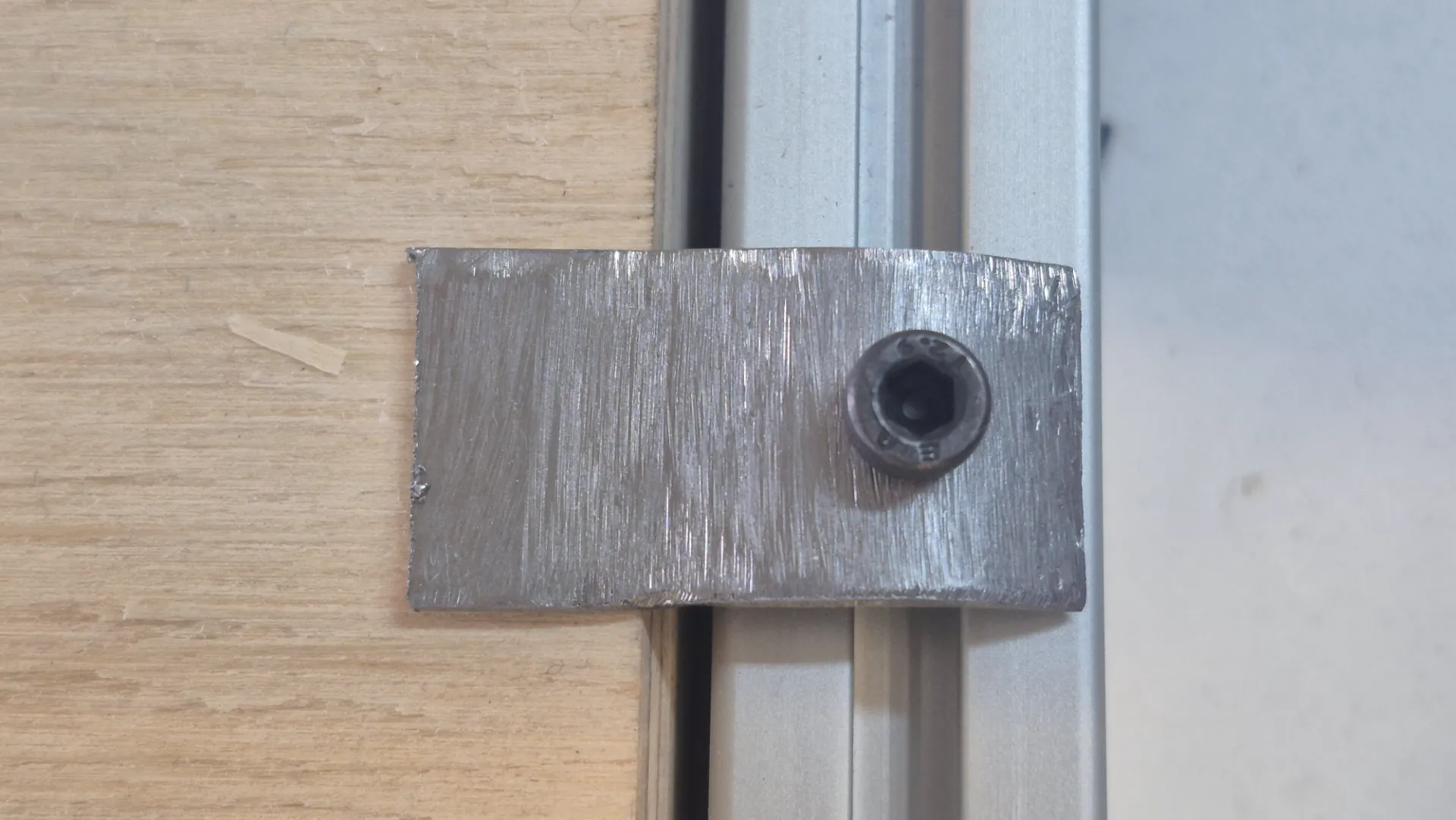
To secure the metal plates to the machine bed, I fabricated custom metal clamps. These clamps were designed to be adjusted using a screw system, providing firm, adjustable pressure that keeps the workpiece perfectly still. Implementing this clamping mechanism was crucial to prevent any movement or vibration during the high-force engraving process, thus ensuring a clean and precise finish on the metal surface.
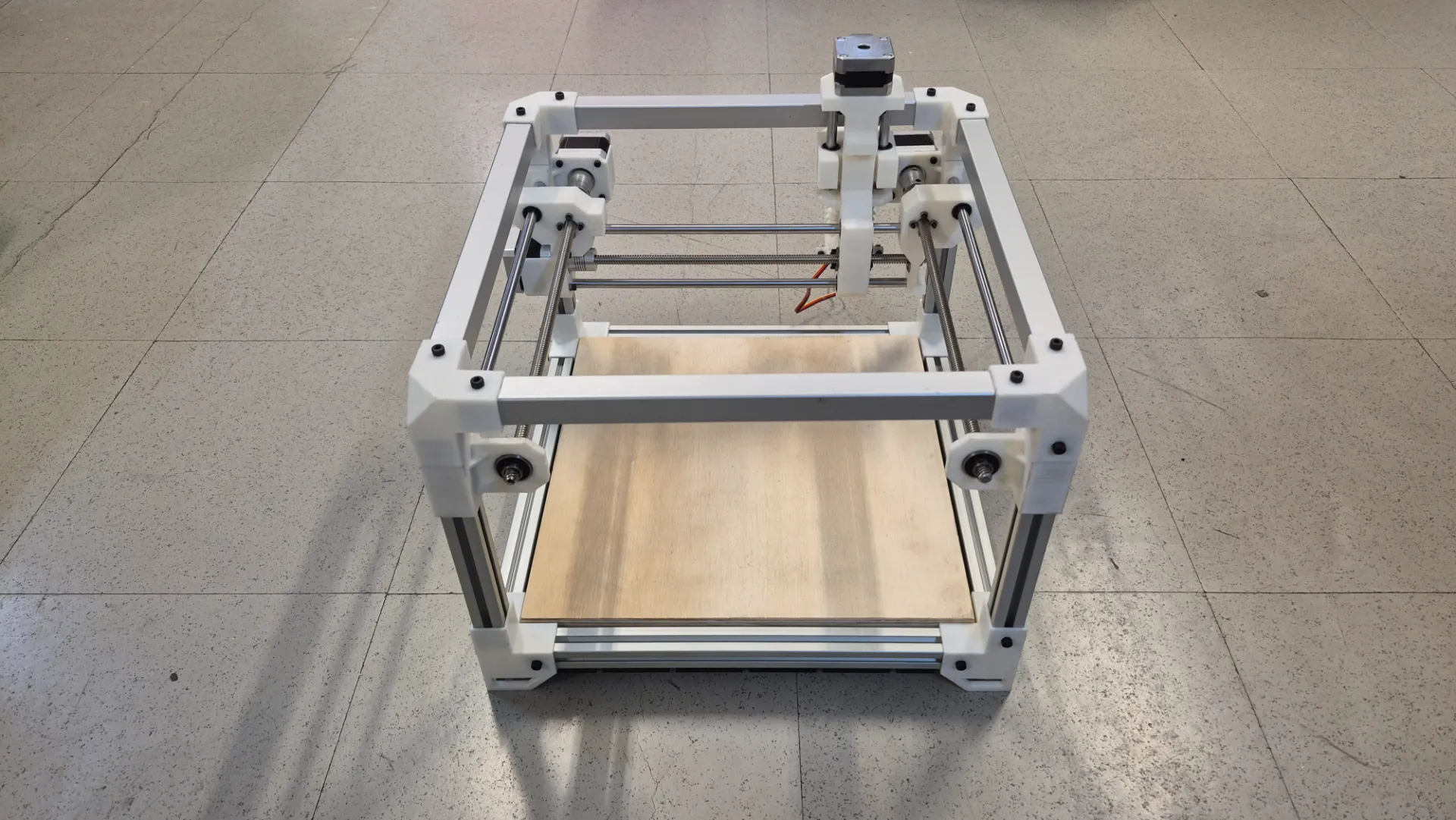
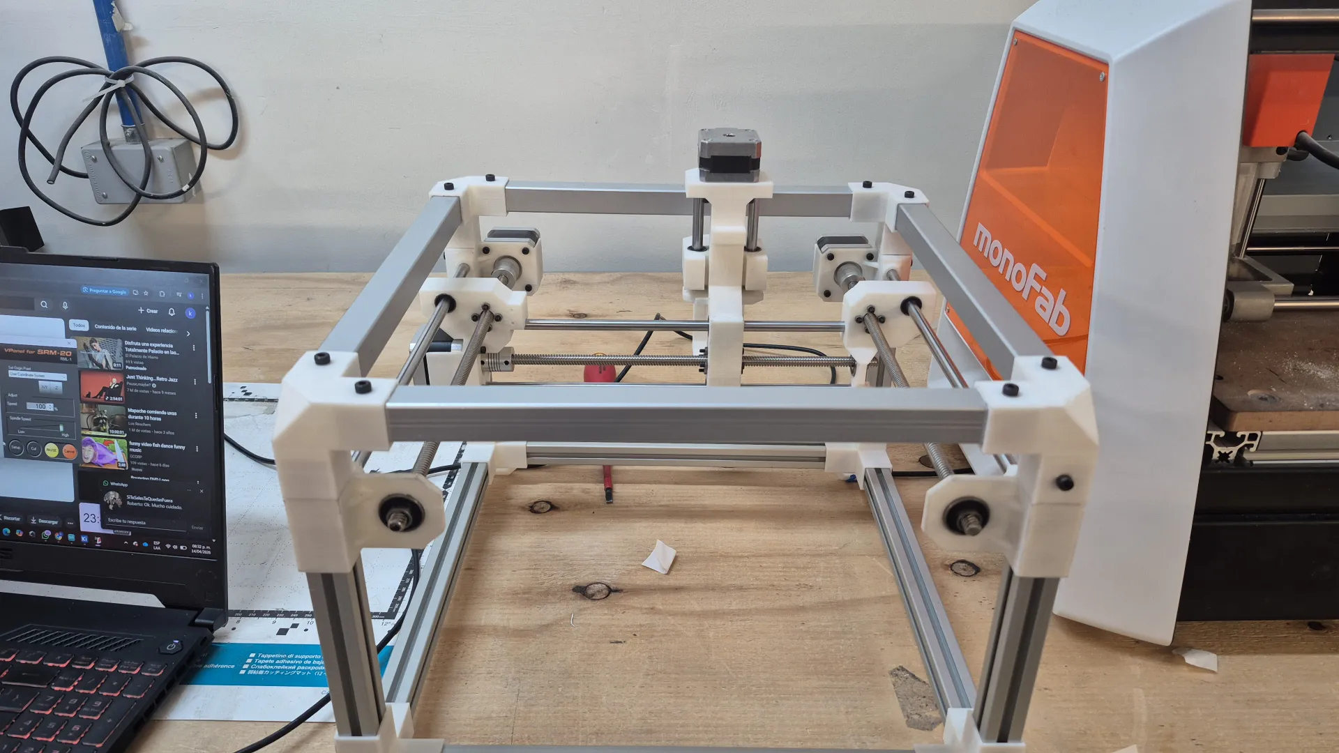
To wrap up the mechanical build, I performed a final pass over the entire structure, securely tightening all the fasteners to guarantee maximum rigidity. Below is the final result of the fully assembled CNC machine: