Week 12. Mechanical Design and Machine Design
Summary
This week we focused on implementing what we saw during the past weeks in this project which is a CNC machine that will engrave metal sheets. This CNC was made in teams by Oscar Hernandez, Majo Ballesteros, Daniela Barranco, and me. I main focus on the electronics production part and help a bit in the coding part, but I will mostly explain the how the PCB from the Raspberry Pi Pico2 and the Control were made and function, also I will explain more in deep the theoreic part which complements with the information and PCB of Daniela Barranco she also made another PCB where the drivers are connected. You can find our machine's group page here.
Machine assignment
Here is the page with all the machines that were made here at Fab Lab Puebla.
1. Electronics theory
1.1 What is a driver and what is it used for?
A motor driver is an integrated circuit that acts as a power bridge between the system's control unit and the motor.
1.1.1 Why is it useful?
A microcontroller's pins can only deliver a few milliamperes (mA), which is insufficient to power a motor. The driver receives low-power logic signals (step and direction) and translates them into high-current and high-voltage pulses to power the motor's coils. It also manages the firing sequence of the coils so that the motor rotates precisely.
1.1.2 Features of the DRV8825 Driver
The DRV8825 Driver is one of the most popular drivers in CNC and 3D machines due to its robustness and precision. We can access to more information through the datahseet.
- Operating Voltage: Supports voltages from 8.2V to 45V.
- Current: Can deliver up to 1.5A per phase without a heatsink, and up to 2.2A with forced ventilation or a heatsink.
- Microstepping: Allows dividing a full step into as small as 1/32 of a step, smoothing movement and increasing precision.
- Protections: Features thermal shutdown for over-temperature, overcurrent protection, and undervoltage protection.
- Interface: Uses a simple two-pin system: STEP (one pulse equals one movement) and DIR (the logic state defines the direction of rotation).
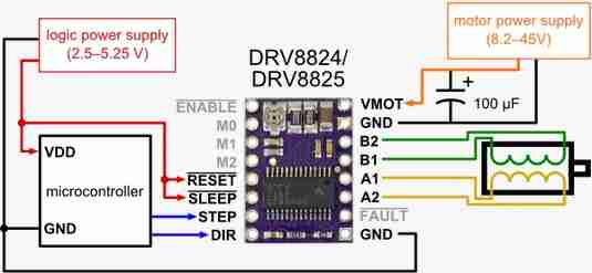
In general, all modules, or at least most, have two important components:
- Separate power supplies for the motor voltage (which typically ranges from 12V to 45V depending on the motor) and for activating the module (3.3V).
- A potentiometer that regulates the current these modules can receive to power the motors. This potentiometer looks like a small screw on the circuit board. The motors may operate with a value that seems to work, but there is a risk of damaging the module. Ideally, you should calculate the correct potentiometer value. I will talk about how to calculate this value in the next section.
1.2 What are Stepper Motors?
A stepper motor is an electromechanical device that converts electrical pulses into discrete mechanical movements (steps). Unlike a conventional DC motor that rotates freely when voltage is applied, a stepper motor moves in precise, known angles.
1.2.1 Why are they useful?
- Open-loop positioning: Because each step is a fixed angle, the system "knows" the tool's position without the need for external sensors (provided no steps are lost due to overloading).
- Hold torque: They have the ability to hold their position firmly when stopped, which is vital in a CNC machine to prevent the milling cutter from moving due to material resistance.
1.2.2 NEMA 17 Characteristics
The term "NEMA 17" strictly refers to the size of the motor's faceplate (1.7 x 1.7 inches), but in the context of standard CNC, its technical specifications are typically:
- Step Angle: Generally 1.8° per step, which equates to 200 steps per complete revolution.
- Torque: Depending on the model (motor length), they typically offer between 40 N·cm and 60 N·cm of holding torque.
- Configuration: These are 4-wire bipolar motors (two independent coils).
- Phases: They operate with two phases, allowing for precise control by reversing the polarity of the coils.
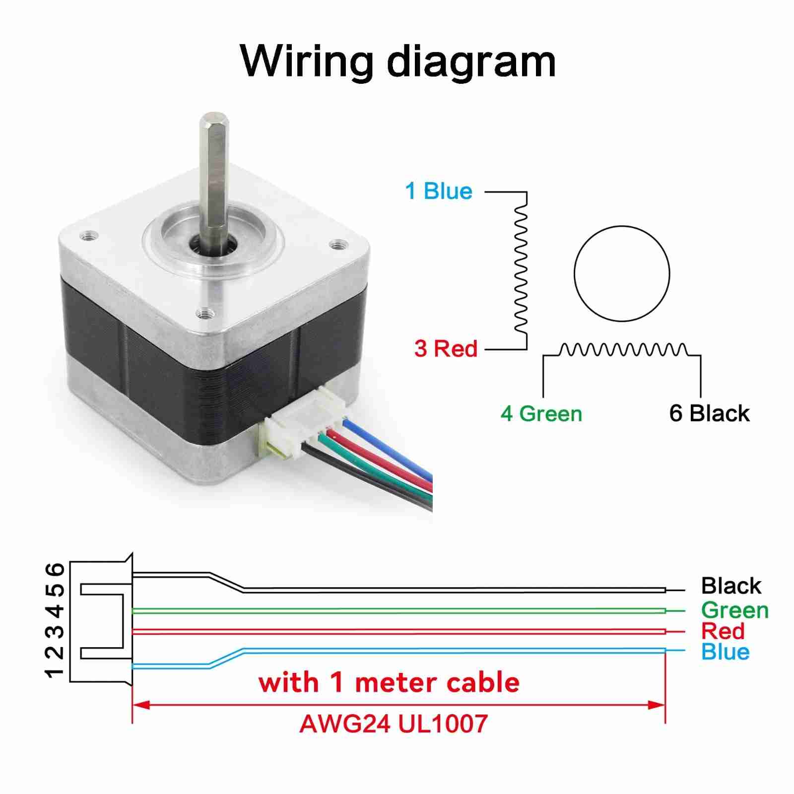
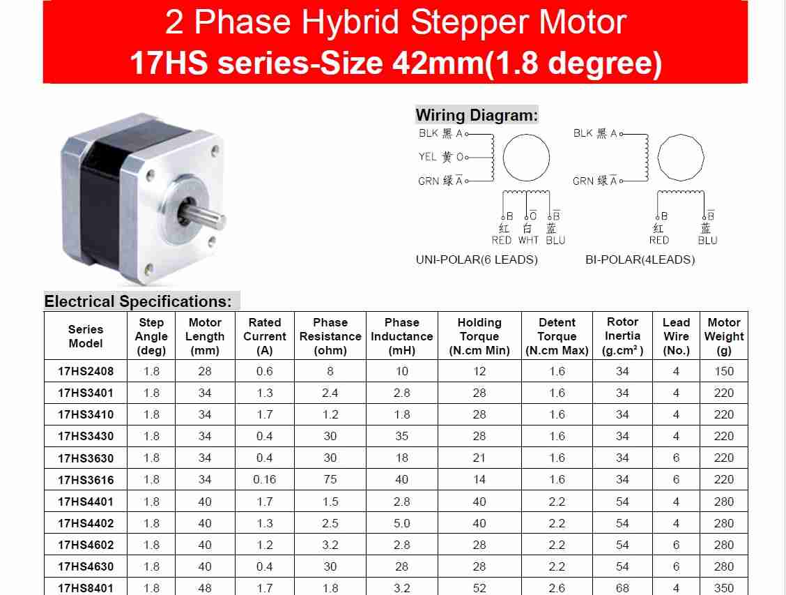
We can know each specific parameter for power the motor through the datahseet. In our case our CNC machine will use the 17HS4401 model so we can use that data, like the voltage and amperage that are values necessary for other calculus.
2. How to calculate the potentiometer value?
As I already said is important to calculate the value of this potentiometer so our module and the motors don't burn.
2.1 Values for our formula
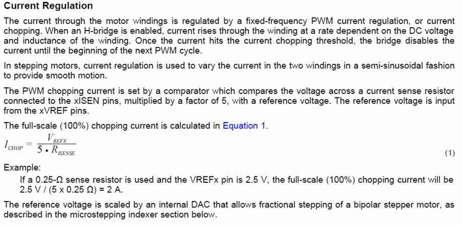
We can find out the voltage value that the potentiometer should have using the driver's datasheet, as it provides a formula for the reference voltage to use and the percentage that can be used.
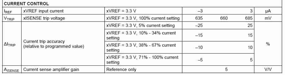
According to this image, we can see that to use 100% of the motor's total current, we can use 71%. The formula to use for the potentiometer value is also obtained from the datasheet.
2.2 The formula
$$I_{CHOP} = \frac{V_{REF}}{5(R_{SENSE})}$$
This formula also was obtained also from the datasheet.
2.3 Obtaining Vref
We know most of the values we want to obtain Vref. Rsense is the resistance of the potentiometer, and Ichop is obtained by multiplying 71% by the motor current, which is known from the motor datasheet and is 1.7A since we use 17HS4401 motors.
$$V_{REF} = (I_{CHOP})(R_{SENSE} \cdot 5)$$
$$V_{REF} = (1.7A \cdot 0.7)(5 \cdot 0.1\Omega)$$
$$V_{REF} = 0.595 V$$
Setting the potentiometer to this value improves the driver's lifespan and performance. A lower setting means the driver won't function, while a higher setting risks burning out the driver, as it will receive more amperage than necessary, potentially damaging the driver or even the motor. The potentiometer should be adjusted with a screwdriver.
3. Why we use the Raspberry Pi Pico2?
The brain for our CNC will be the Raspberry Pi Pico 2 due to its multiple pins, It allowed us to have all the components connected directly to the microcontroller. It works the same as a Xiao rp2040 or rp2350 the only difference is that this one is a development board and the other was the pure microcontroller which is why it had less pins. Also as we don't need wifi or Bluetooth functions we didn't use a microcontroller with those functions like the esp32.
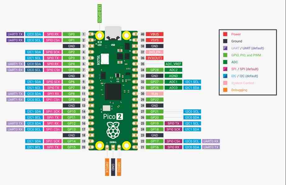
4. "Brain" PCB, Pico2 output pins
All the PCB's would be modular. This PCB is the brain of our machine because it has the Pico2 outputs to send data to the control, the modules PCB's and to the servomotor that will be used to rotate the tool that will be used. Before continue is important to say that Daniela Barranco did a PCB where all the components were in the same PCB but didn't work and also a lot of 0ohm resistors were used so thats why we decided to make all the PCB's in a modular way.
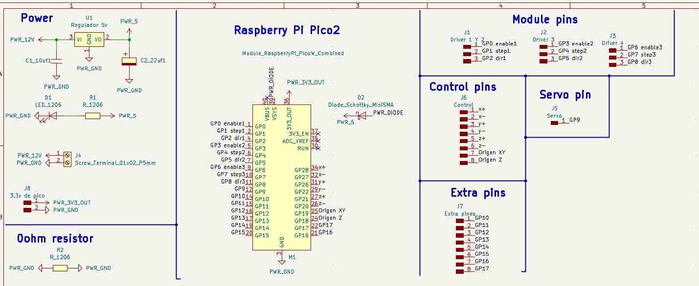
From all the components the new ones are:
- Screw Terminals: Are like pin sockets but for a more robust use.
- Diode: It's like a one-way valve for electricity. In one direction it lets the current flow freely, and in the other it blocks it completely.
Here is the PCB layout in KiCad
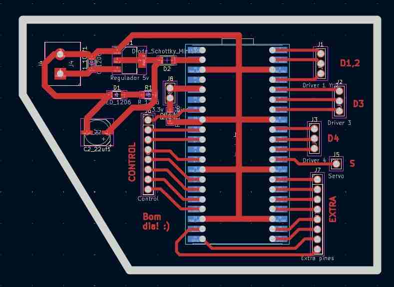
Here is the PCB already soldered. A small recommendation is to not put 1 pin header alone beacuse if will be difficult to weld.

5. "Control" PCB, move axis and set origins
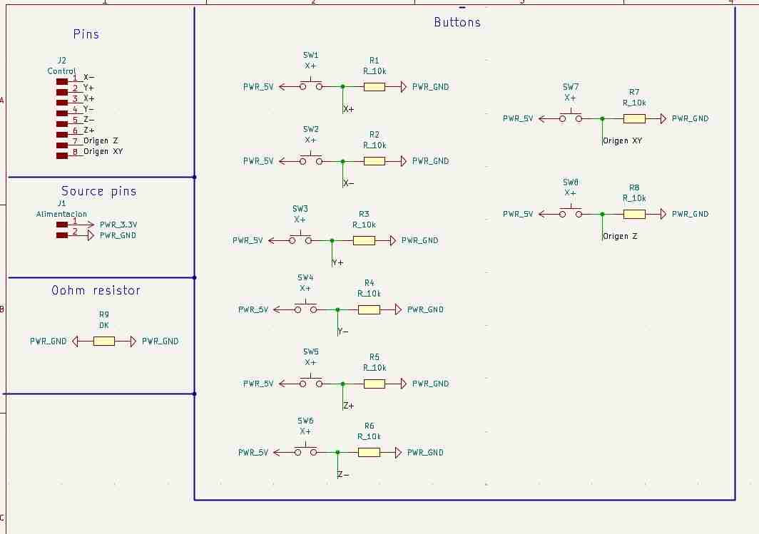
The function of this pcb is for the user to move freely along the axis x,y and z ans to declare where the origins from x,y and z are; similar like a router or also the monofabs used here ar Ibero Puebla.
The Control is conected to the brain through pins and jumpers basically the control sends the high or low signal by pull down buttons to the brain, using SMD push buttons and 10 Kohm resistors, is also important to mention that the control PCB is sourced with 3.3V from an external power source. we didn't use the 3.3V out from the Pico2 because the inner volatge regulator from the Pico2 will start working and will burn the Pico2 after a few minutes due to the many components and how they use the voltage, is only recommended to use the output if it is only a low consumption sensor or button but even doing that you are outting in danger your microcontroller.
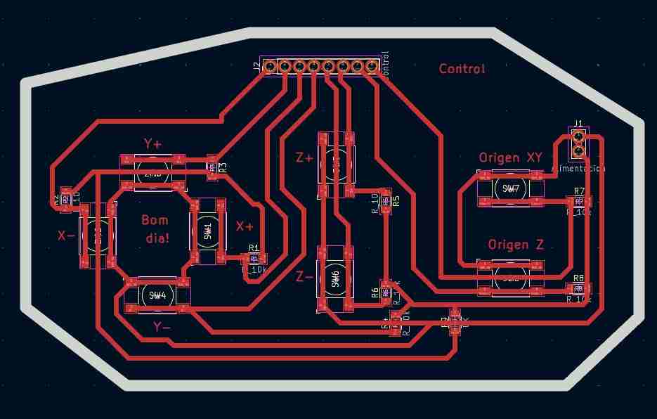
Here is the PCB layout in KiCad
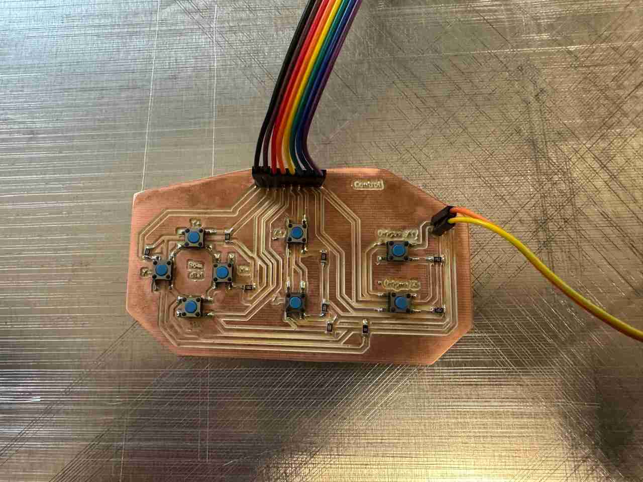
Here is the PCB already soldered.
7. Results
For testing both PCB's I made a code that prints Pressing # being # the axis that is moving.
                    const int pinOrigenZ  = 18;
                    const int pinOrigenXY = 19;
                    const int pinZMinus   = 20;
                    const int pinZPlus    = 21;
                    const int pinYMinus   = 22;
                    const int pinYPlus    = 26;
                    const int pinXMinus   = 27;
                    const int pinXPlus    = 28;

                    void setup() {

                    Serial.begin(115200);


                    pinMode(pinOrigenZ,  INPUT);
                    pinMode(pinOrigenXY, INPUT);
                    pinMode(pinZMinus,   INPUT);
                    pinMode(pinZPlus,    INPUT);
                    pinMode(pinYMinus,   INPUT);
                    pinMode(pinYPlus,    INPUT);
                    pinMode(pinXMinus,   INPUT);
                    pinMode(pinXPlus,    INPUT);

                    Serial.println("Consola de control de ejes lista...");
                    }

                    void loop() {


                    if (digitalRead(pinOrigenZ) == HIGH) {
                        Serial.println("Origen Z presionado");
                        delay(200); // Debounce simple
                    }

                    if (digitalRead(pinOrigenXY) == HIGH) {
                        Serial.println("Origen XY presionado");
                        delay(200);
                    }

                    if (digitalRead(pinZMinus) == HIGH) {
                        Serial.println("z- presionado");
                        delay(200);
                    }

                    if (digitalRead(pinZPlus) == HIGH) {
                        Serial.println("z+ presionado");
                        delay(200);
                    }

                    if (digitalRead(pinYMinus) == HIGH) {
                        Serial.println("y- presionado");
                        delay(200);
                    }

                    if (digitalRead(pinYPlus) == HIGH) {
                        Serial.println("y+ presionado");
                        delay(200);
                    }

                    if (digitalRead(pinXMinus) == HIGH) {
                        Serial.println("x- presionado");
                        delay(200);
                    }

                    if (digitalRead(pinXPlus) == HIGH) {
                        Serial.println("x+ presionado");
                        delay(200);
                    }

                    delay(10);
                    }
If you want to see how the Brain pcb works with the module PCB you can check the Daniela Barranco page, where she talks about how she created that PCB and how it works.
8. Files created
Click on the "Download ZIP" to download all the files I made for this week assignment.