Final project: Spiderbot
Summary
Spiderbots are tiny robots made by Spider-man who would help him in his duties as a hero, allowing him to control them manually and even make them follow him, but...
Is this even possible in real life?, we will find out.
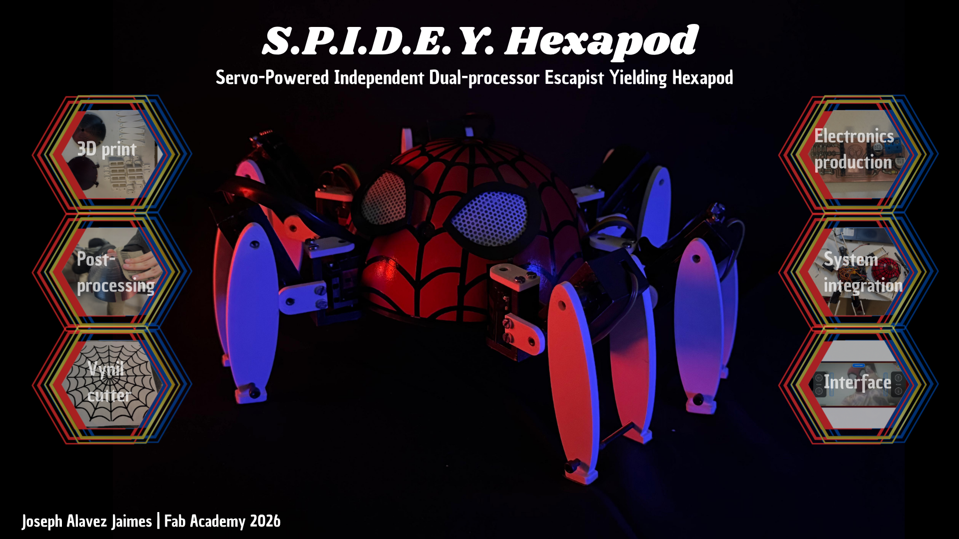
S.P.I.D.E.Y. Hexapod
1. Why this project?
Spider-man is my favorite superhero since I have memory, I love cosplaying as him and visiting childrens in hospital or walking around the city taking pictures with children and making sure they have a great memory with his favorite superhero and the most important thing, e insperes me to be a better person and never giving up.
I always wanted to have a realistic spiderbot but the ones that are available are expensive for what they can do; most just move on wheels at the bottom, with the legs being purely decorative. The most realistic one in terms of movement is the Disney version, as it does appear to have moving legs, but it moves very slowly, not quickly like a real spider.
My main goal is to create a spiderbot that moves like a spider and that can be controlled with phone. As a second goal but not main one is to integrate a system that allows the spiderbot to follow you like if it was a mascot.
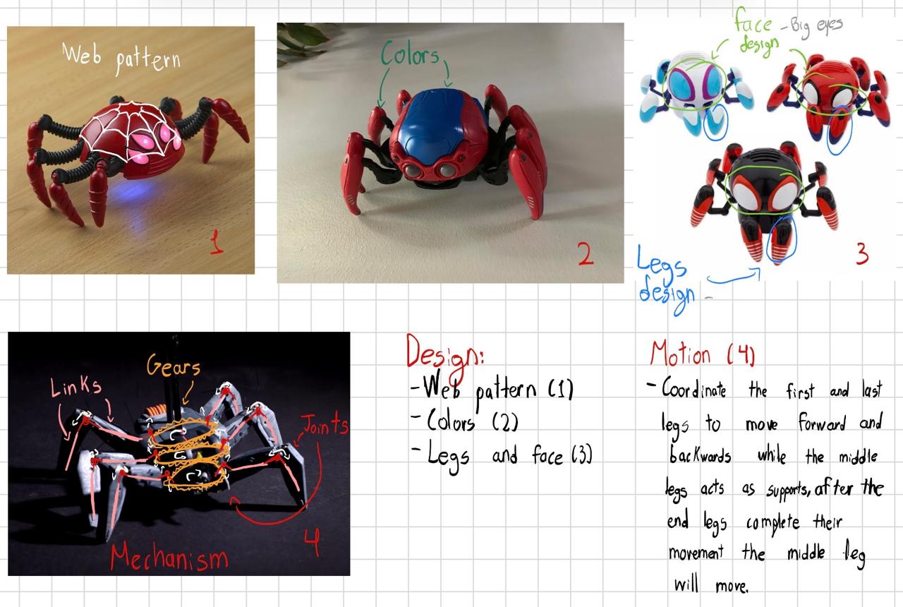
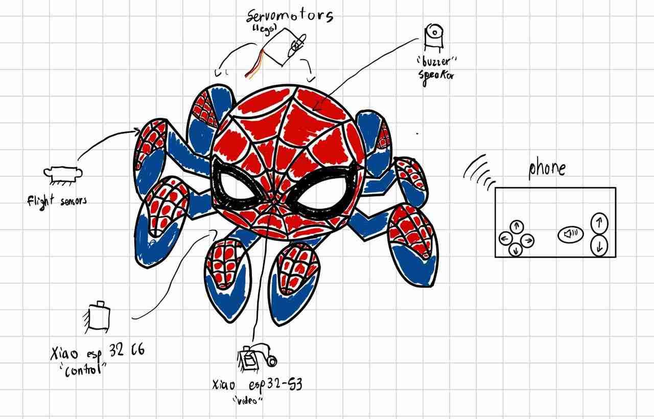
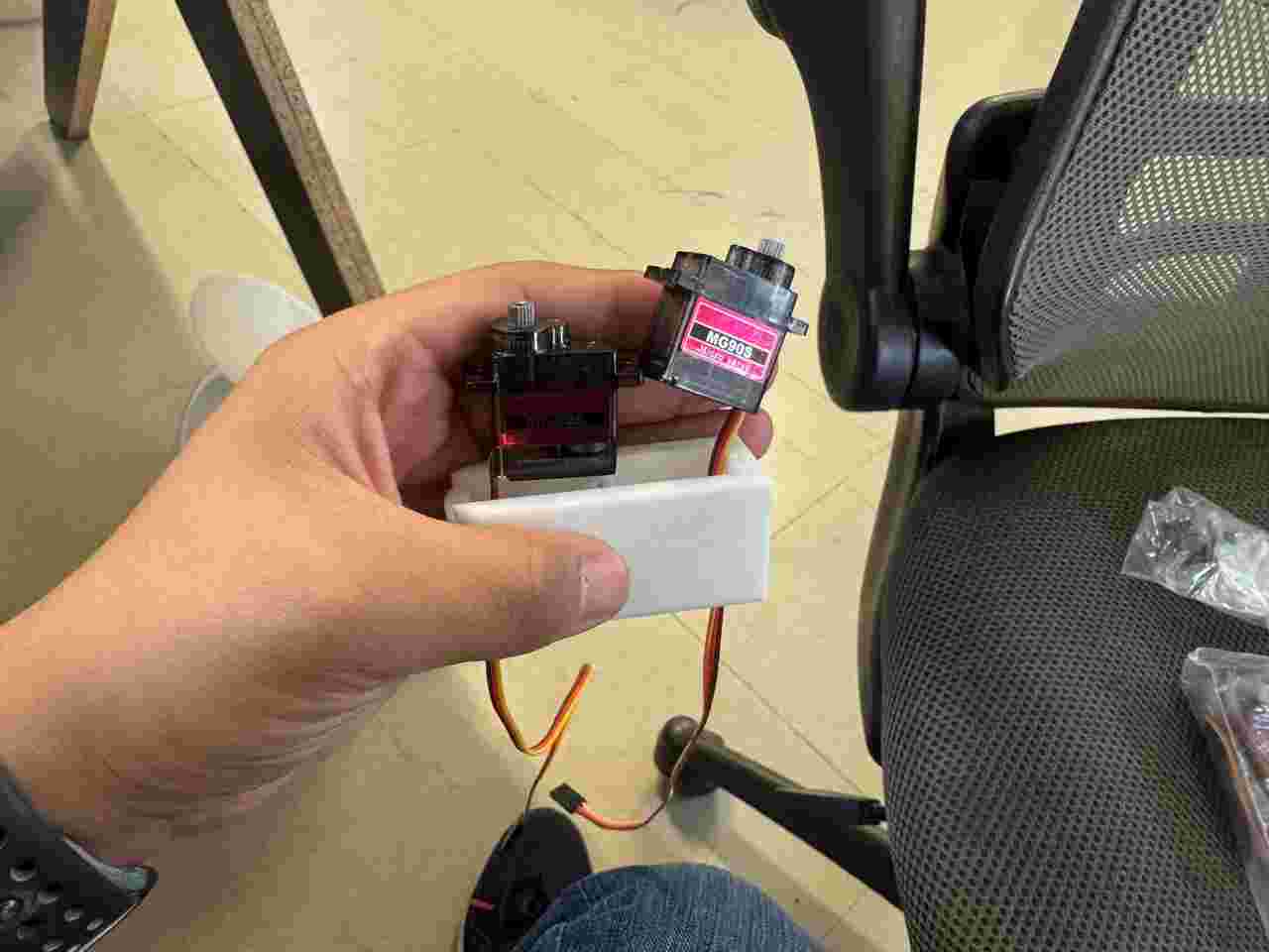
As I would like that my spiderbot moves quick I would use the mechanism of image 4 since is the one that allows a quick response because it will be controlled by servomotors. For the Communication I'll use Wi-Fi because it it has a greater communication range than a Bluetooth module due to that the ESP32-S3-WROM-2 will be perfect as it already has integrated a Wi-Fi and allows me to have free pins if I want to add more sensors or modules to the spiderbot. Last but not least a tiny speaker that make a noise so you can notice him.
1.1 Sketching
I based the appearance on the 4 images that were shown, mixing it because they have elements that I do like the web pattern (1), colors (2), face and legs design (3) and the mechanism (4), adapting these references to the design I would like my spiderbot had.
Systems integrating the project
- Motion: Servomotors
- Microcontroler: Xiao esp32 C6
- Communication: Wi-Fi and phone
- Noise generation: Passive buzzer
- Video retransmisision: Xiao esp32 S3
- Coalition detection: Flight sensors (Vl53lXX-V2)
2. Bill of materials (BOM)
This is my current Bill of materials:
Mechanical Components
| Item | Detail | Quantity | Unit price (dollars) | Source link |
|---|---|---|---|---|
| PLA filament | white color | 1Kg | $15 | Amazon |
| Servomotors | MG90s | 18 | $1.95 | Aliexpress |
| Washer | M2 | 12 | $0.02 | Local (N/A) |
| M3 screws | 5mm | 16 | $0.17 | Local (N/A) |
| M3 screws | 12mm | 18 | $0.17 | Local (N/A) |
| M3 screws | 20mm | 24 | $0.17 | Local (N/A) |
| M5 screws | 10mm | 6 | $0.28 | Local (N/A) |
| M3.5 screws | 51mm | 6 | $0.1 | Local (N/A) |
| Sandpaper | #120 | 1 sheet | $0.5 | Local (N/A) |
Electronic Components (External to PCB)
| Item | Detail | Quantity | Unit price (dollars) | Source link |
|---|---|---|---|---|
| Gens Ace 2S 7.4V 2200mAh 35C LiPo Battery | N/A | 1 | $20 | Amazon |
| Servomotor module | PCA9685 | 2 | $7 | Local (N/A) |
| XL4016 module | Power stage | 1 | $7 | Local (N/A) |
| MP1584EN module | Logic stage | 1 | $3 | Local (N/A) |
| Jumpers | mixed | 10 | $0.06 | Local (N/A) |
PCB Components
| Item | Detail | Quantity | Unit price (dollars) | Source link |
|---|---|---|---|---|
| Xiao esp32 C6 | Control | 1 | $9 | Aliexpress |
| Xiao esp32-S3 | Video | 1 | $14 | Aliexpress |
| OV2640 Camera Module | Enhance video | 1 | $8.5 | Aliexpress |
| flight sensor Vl53lXX-V2 | Proximitty | 2 | No se | Local (N/A) |
| Pin header | through hole | 25 | $0.4 | Local (N/A) |
| Female pin | through hole | 20 | $0.4 | Local (N/A) |
| Copper plate | Fiber glass | 1 | $0.5 | Local (N/A) |
| Electrolytic capacitor | SMD, 100uF | 2 | $0.34 | Local (N/A) |
| Ceramic capacitor | 104 | 1 | $0.17 | Local (N/A) |
| LED | SMD, whatever color | 1 | $0.15 | Local (N/A) |
| Resistor | SMD, 330 ohm | 1 | $0.06 | Local (N/A) |
| Two-terminal terminal block | through hole | 1 | $0.1 | Local (N/A) |
| Jumpers | mixed | 20 | $0.06 | Local (N/A) |
Aesthetic
| Item | Detail | Quantity | Unit price (dollars) | Source link |
|---|---|---|---|---|
| PLA filament | white color | 1Kg | $15 | Amazon |
| TPU filament | white color | 1Kg | $16 | Amazon |
| Spray paint | mixed colors | 500g | $10 | Local (N/A) |
| Sandpaper | #99 | 1 sheet | $0.5 | Local (N/A) |
| Sandpaper | #200 | 1 sheet | $0.5 | Local (N/A) |
| Sandpaper | #400 | 1 sheet | $0.5 | Local (N/A) |
| Vynil | Black | 1 | $9.1 | Local (N/A) |
| Microperforated vinyl | White | 1 | $8.32 | Local (N/A) |
| Bottle of mineral water | Peñafiel 1 liter | 1 | $1 | Local (N/A) |
3. Key weekly developments
The weeks that were the most important in devoloping the spiderbot were this:
- Week 3: Web pattern
- Week 5: 3D print
- Week 9: Flight sensors and PCB
- Week 11: Wifi communication
- Week 14: The "Control" interface
- Week 15: System integration idea "head"
3. Body design
This skeleton design will be used as the basis for everything, because at the beginning of any robotics project it is important to maintain simple geometric figures at the beginning in order to later make redesigns based on that simple figure but which can integrate aesthetic design.
2.1 Body sketch
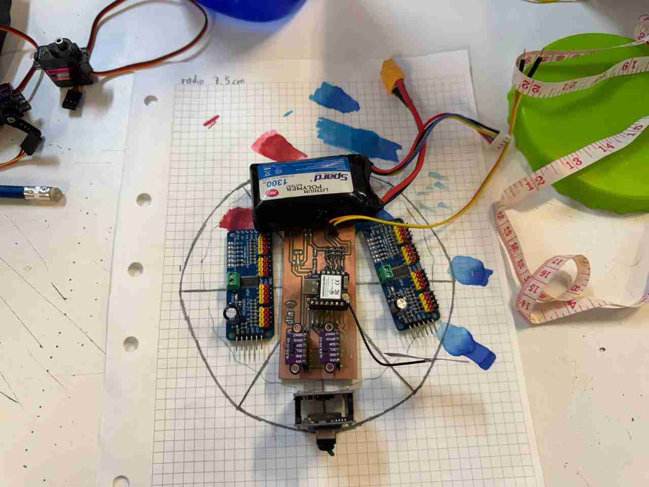
First I sketched the area of the body by putting inside all the components that I've considered the spiderbot will have.
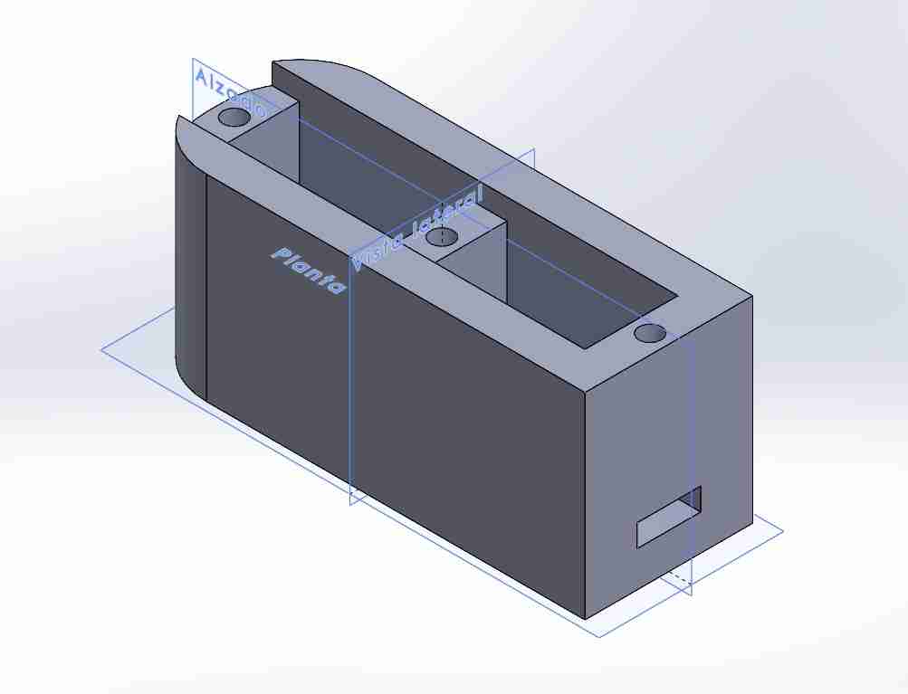
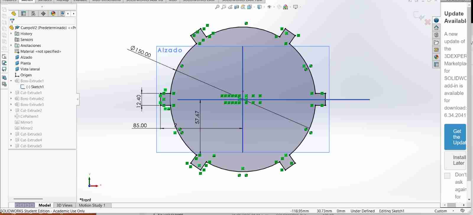
2.2 Body in SolidWorks
After that I measure the ratio to sketch the body on SolidWorks, measuring a ratio of 7.5 cm; then I added the walls where the servomotors legs will be attached.
Here is how the version 1 body looks like, is important to notice that the body has holes to use screws to attach other pieces (I will explain this pieces next) of the legs and also the servomotors. I will use M3 screws.
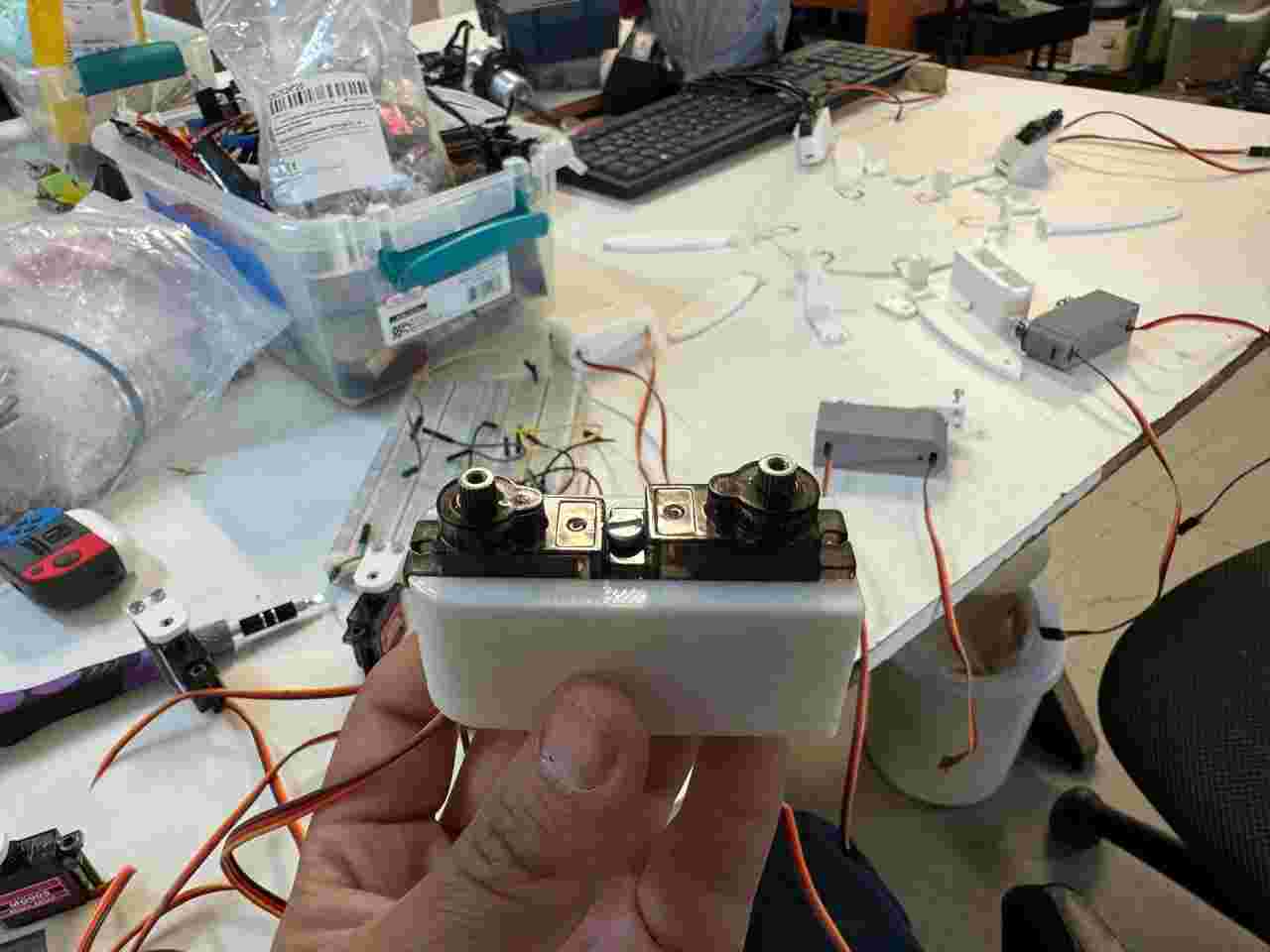
2.3 Servo adapter
This piece fits on the gear of the servomotor, to allow him to move other pieces.
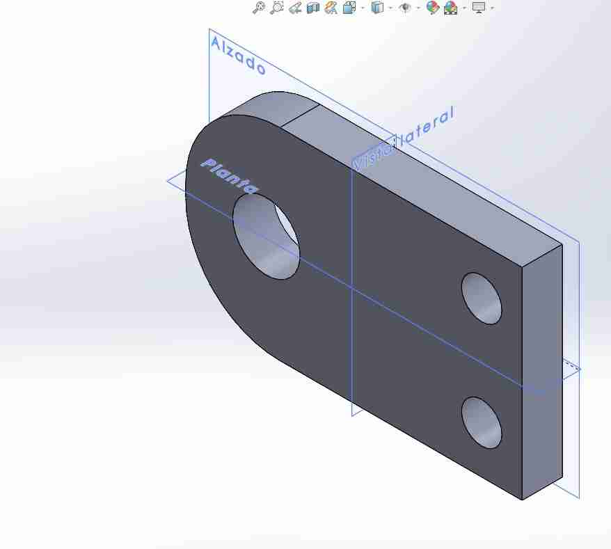
2.4 Coxa-femur
This piece links the coxa with the femur, attaching to the servo adapter, serving as a part which helps to maintain the rotation of the coxa servomotor.
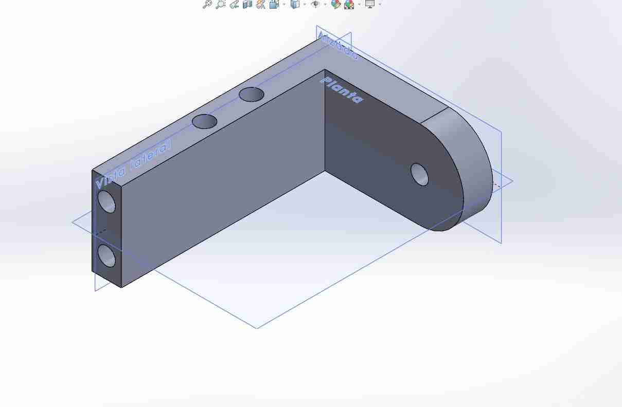
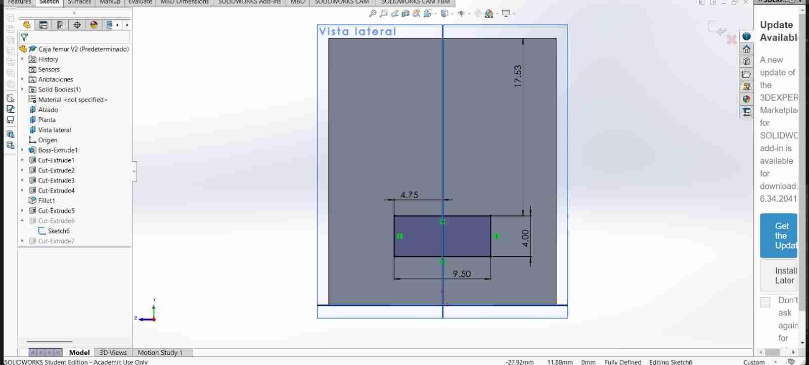
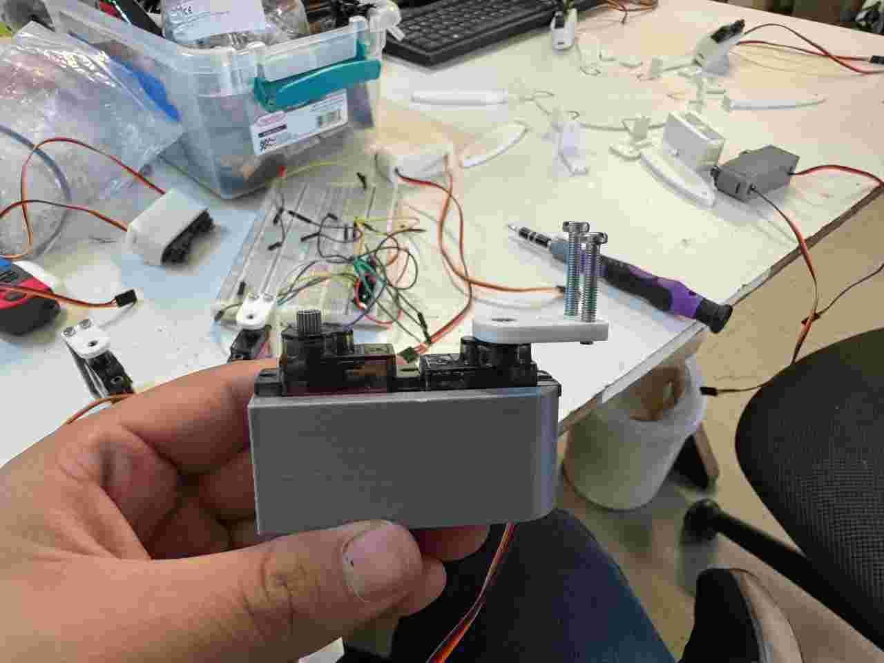
2.4 Femur box
This part might seem unnecessary since the tibia and femur servomotors can be joined with just a screw, but this isn't sufficient because that connection is weak due to the constant movement of the servomotors. Therefore, its purpose is to provide rigidity and stability to the femur.
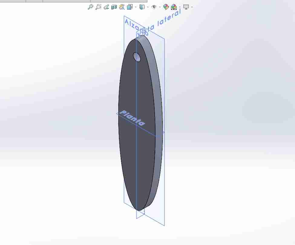
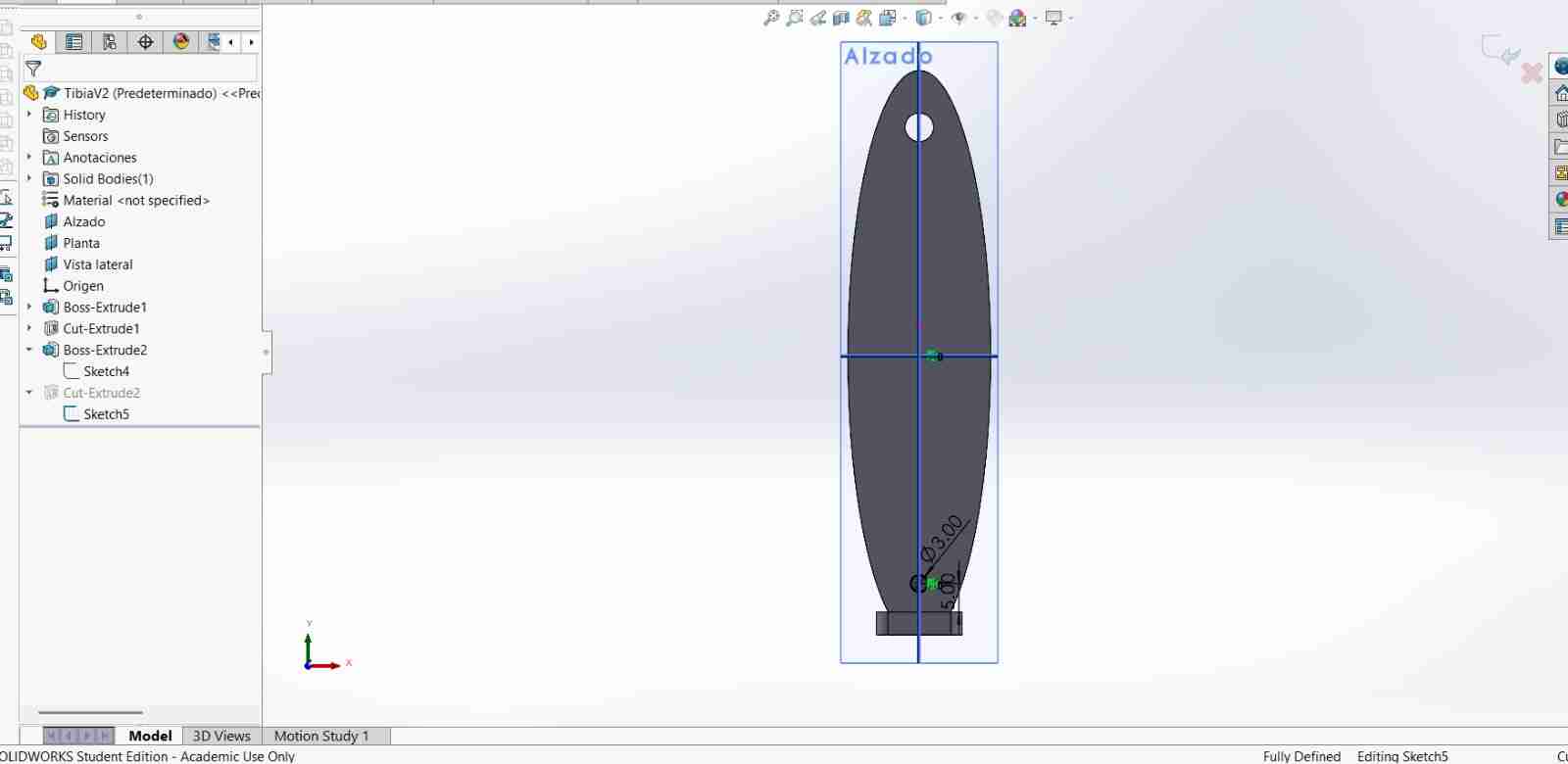
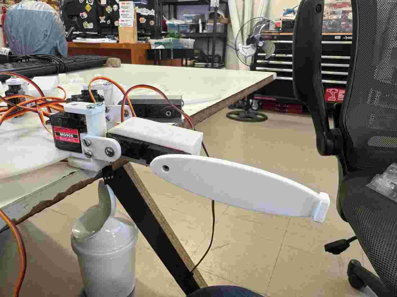
2.5 Tibia
This part is the complete tibia only attached woth the servomotor gear and its respectively screw. I designed it like a oval, because I want to test if it can have this geometric shape for the final design of the legs.
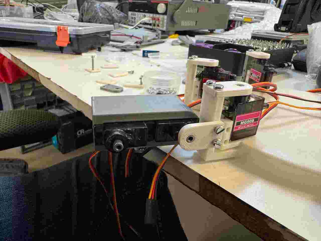
2.6 Assembly
Before installing the servomotors, make sure that the gears have no play, as this can affect the operation of the entire assembly.
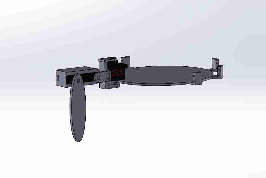
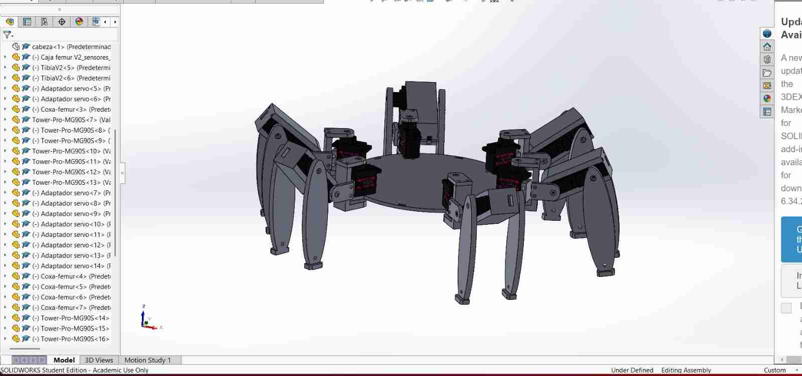
2.6.1 In SolidWorks
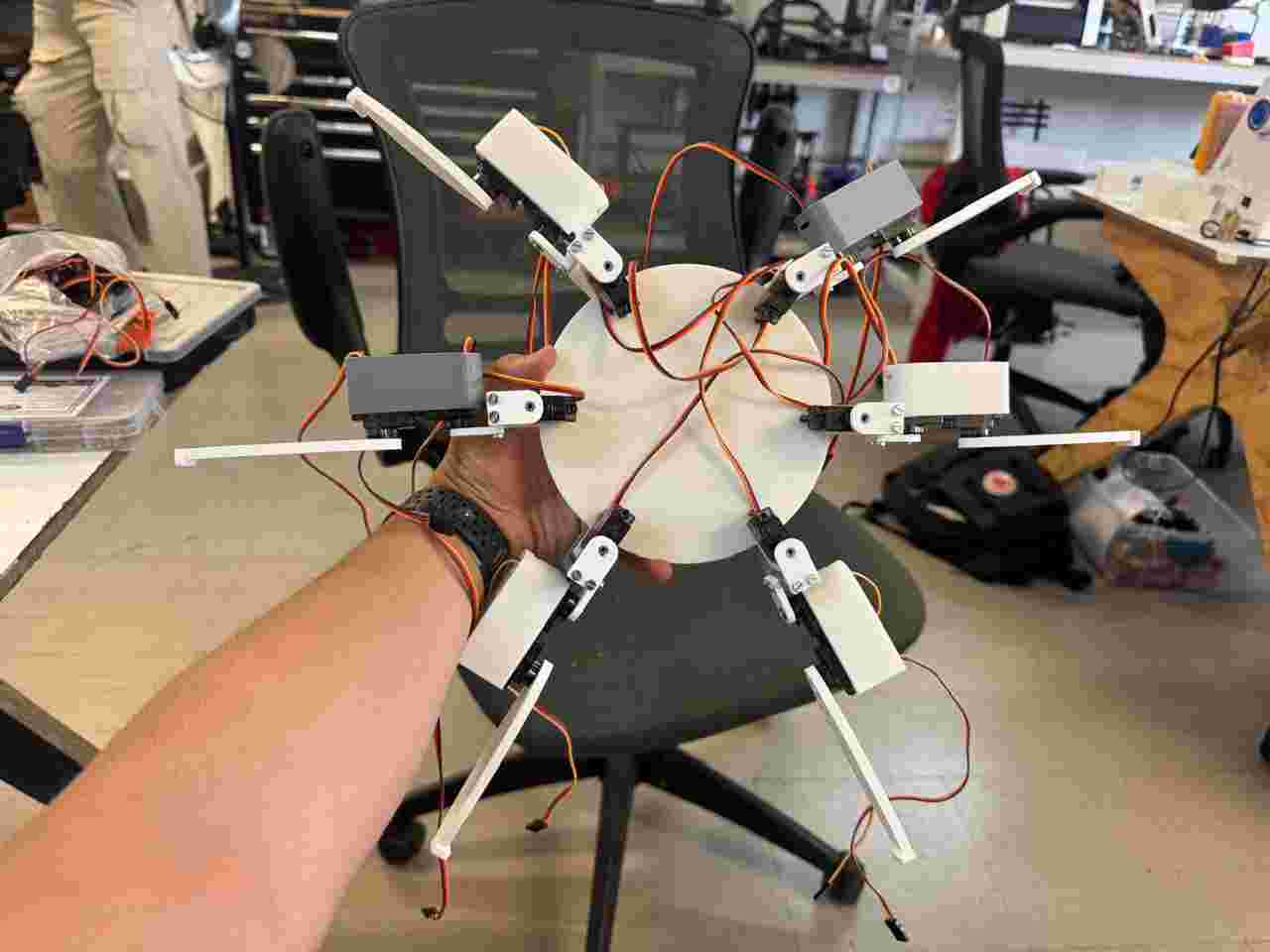
I then assembled the complete body to see if the pieces were designed correctly. My recommendation is to have the piece that will be fixed, in my case the body, and then design and test every piece in the assemble to make the corrections at the moment.
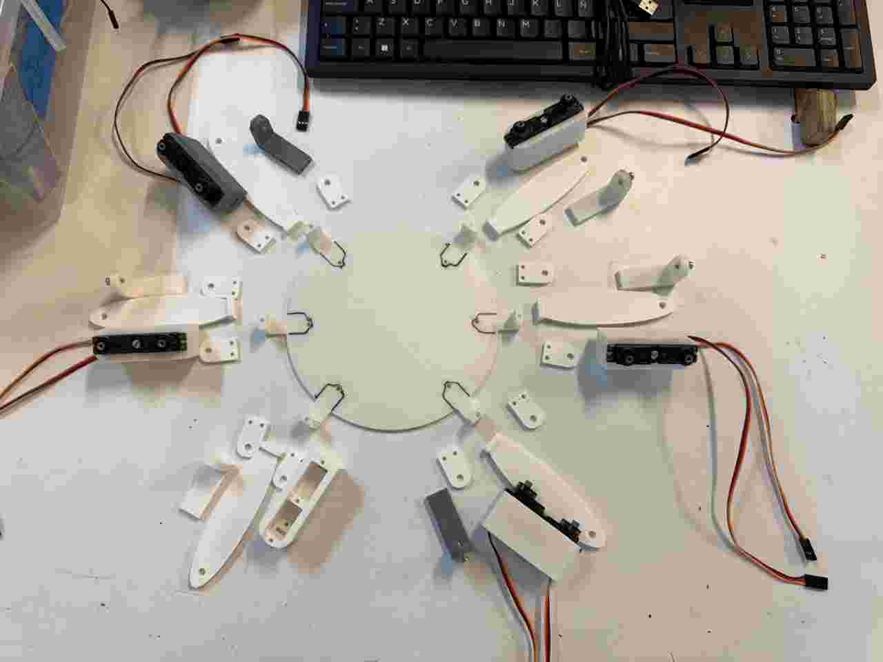
2.6.2 In physical
I 3D printed the pieces, buy some M3 screws and start linking the pieces; starting from the inside out.
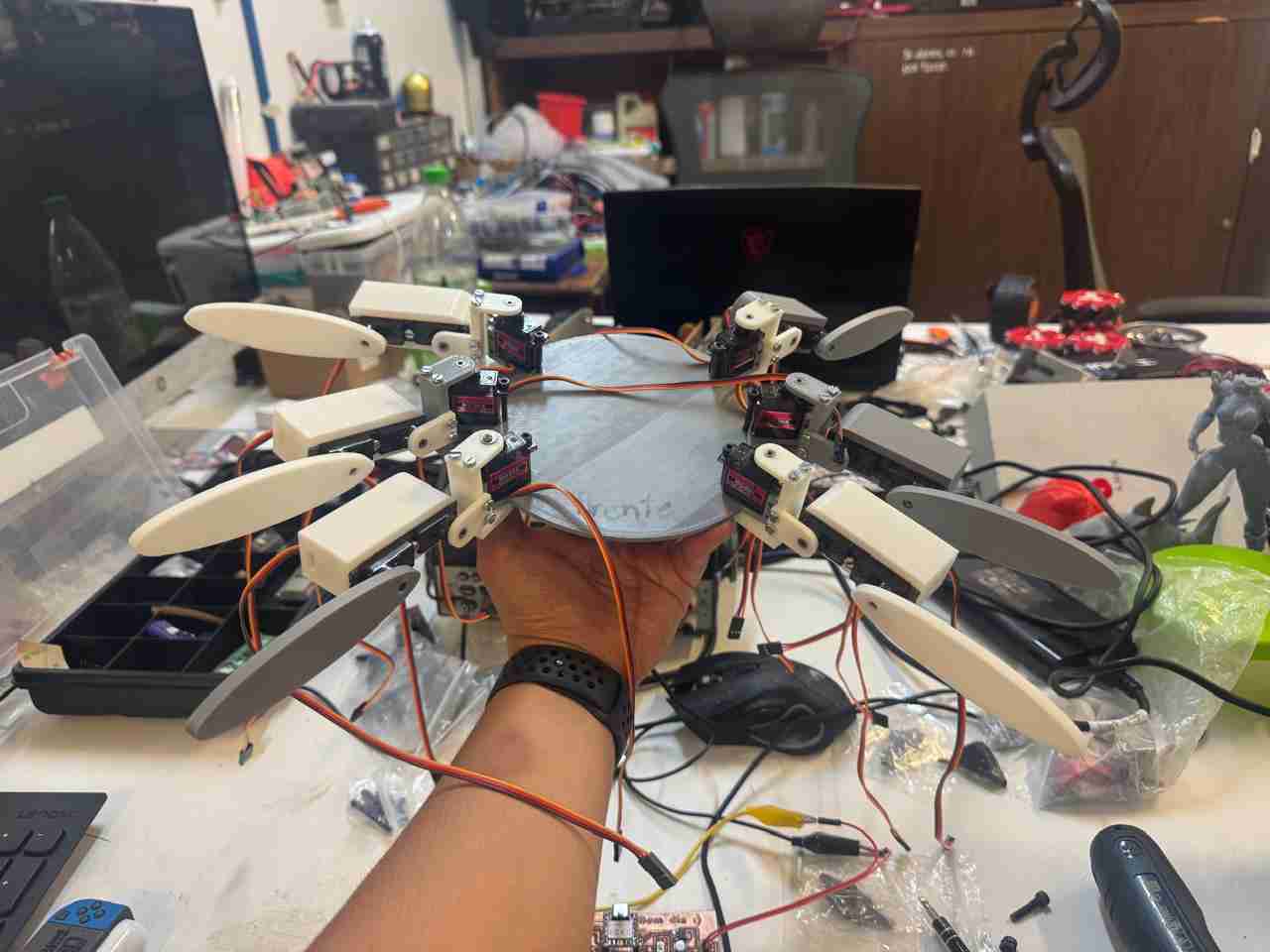
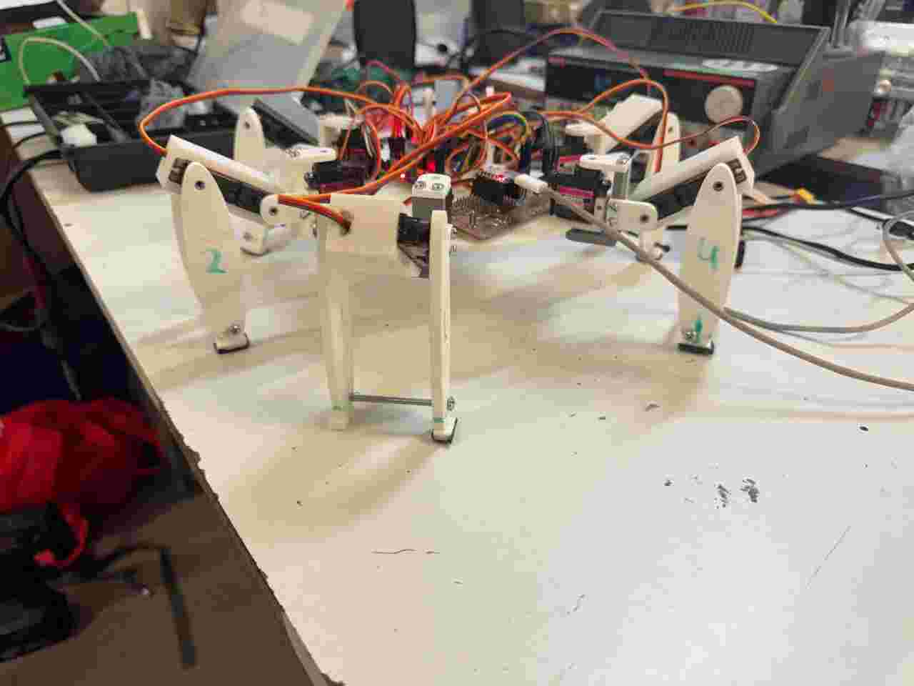
I tested the legs manually and they all moved correctly, so when the servos are powered they should move fine.
In this video I show the 3 degrees of freedom that one leg (coxa, femur and tibia) has, therefore, each leg has the same degrees of movement.
While I was testing the legs, I realized that the contact surface between the floor and the tibias was very small, and it didn't help that they weren't centered (by this I mean centered to the support point of the femur-coxa piece, which makes it less stable). Also I noticed that it would be better if the spiderbot had more contact with the soil so I also will add another tibia piece.
2.7 Changes to the some pieces
I modified:
- Femur box
- Tibia
- Body
2.7.1 Femur box V2
I added a hole that is concentrar to the servomotor gear to place there a M5 screw that will help to increase the contact surface.
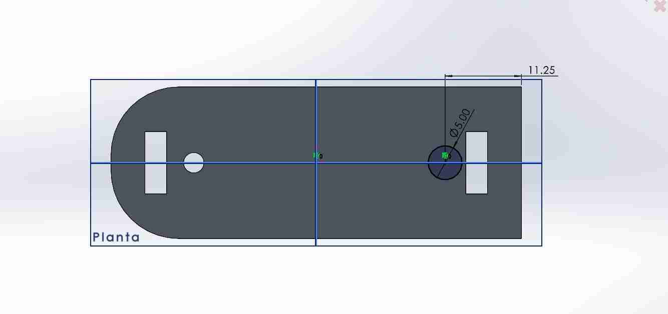
I made the boxes where the servo motor cables pass through larger because in the previous version they would get stuck and I really didn't want to break the servo cables, so I decided to make this box bigger.
2.7.2 Tibia V2
For the tibia I changed the tip so it makes contact with a planar surface, extruding the sketch. Also on this new flat I glue sandpaper #120 that will work as anti-slip for the legs
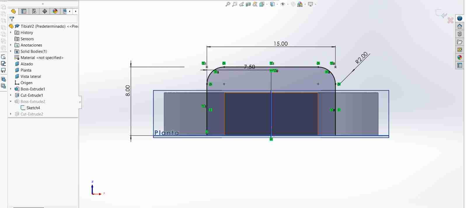
Last but not least I cutted a hole above the new tip to fit the M3.5 screw.
2.7.3 Body V2
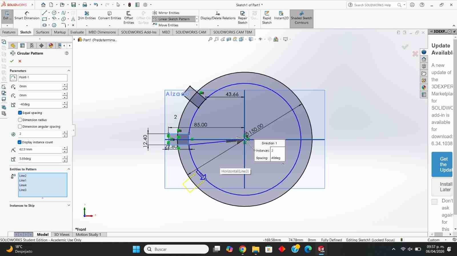
I increased the space between the coxas so the body doesn't have mobility problems. I used circular pattern in one direction increasing by 305 degrees, then use mirror to duplicate the part we got from circular pattern and then mirror to duplicate the other half.
I made a small slit so that the servo motor cables are not squeezed between the servo and the body, improving their use and lifespan.
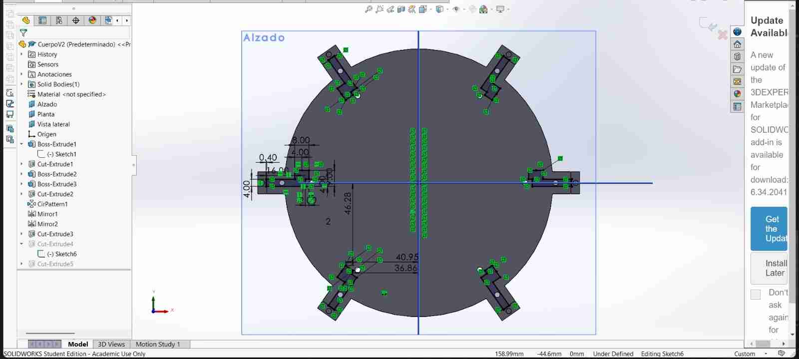
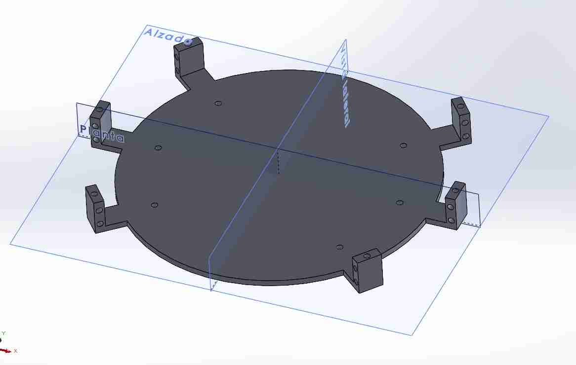
Finally, cut some rectangles around the body where the head of the system integration part will be attached, using press-to-fit joints.
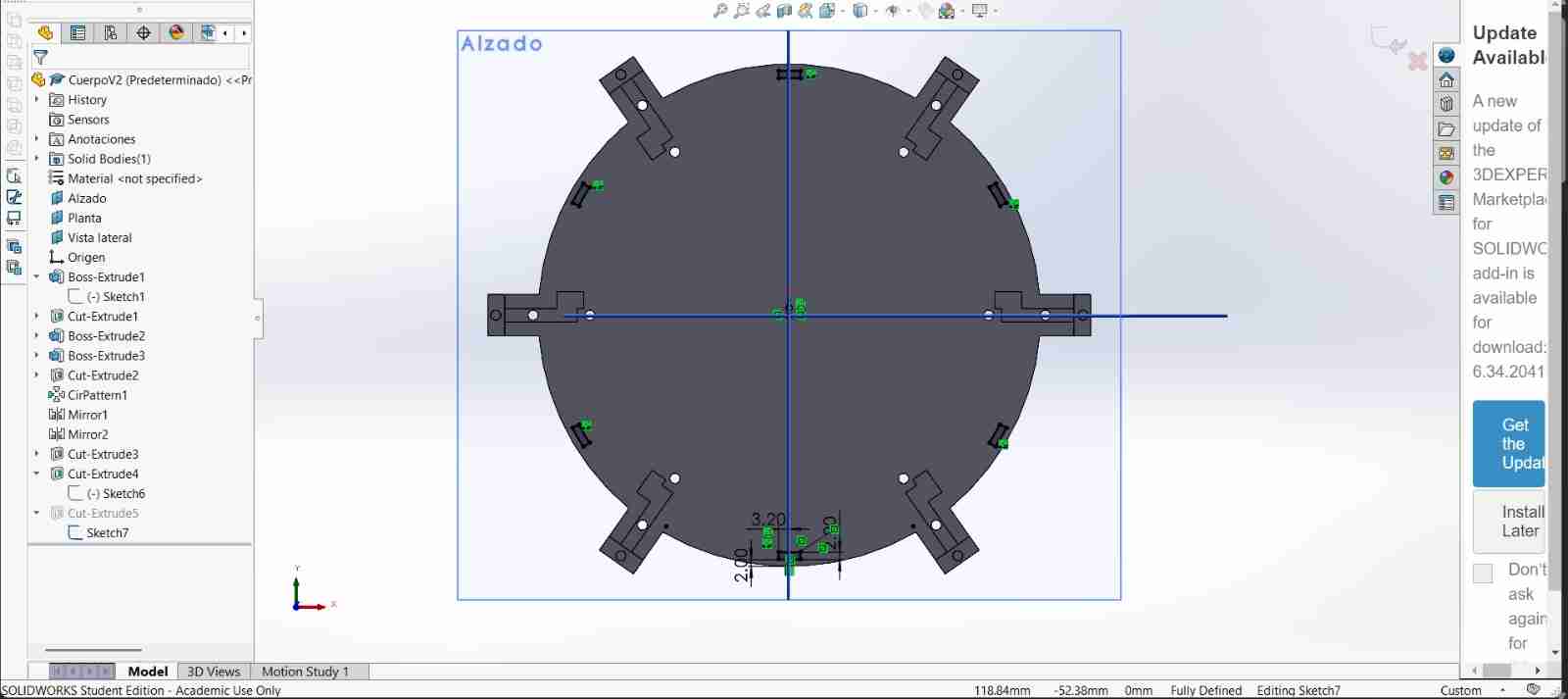
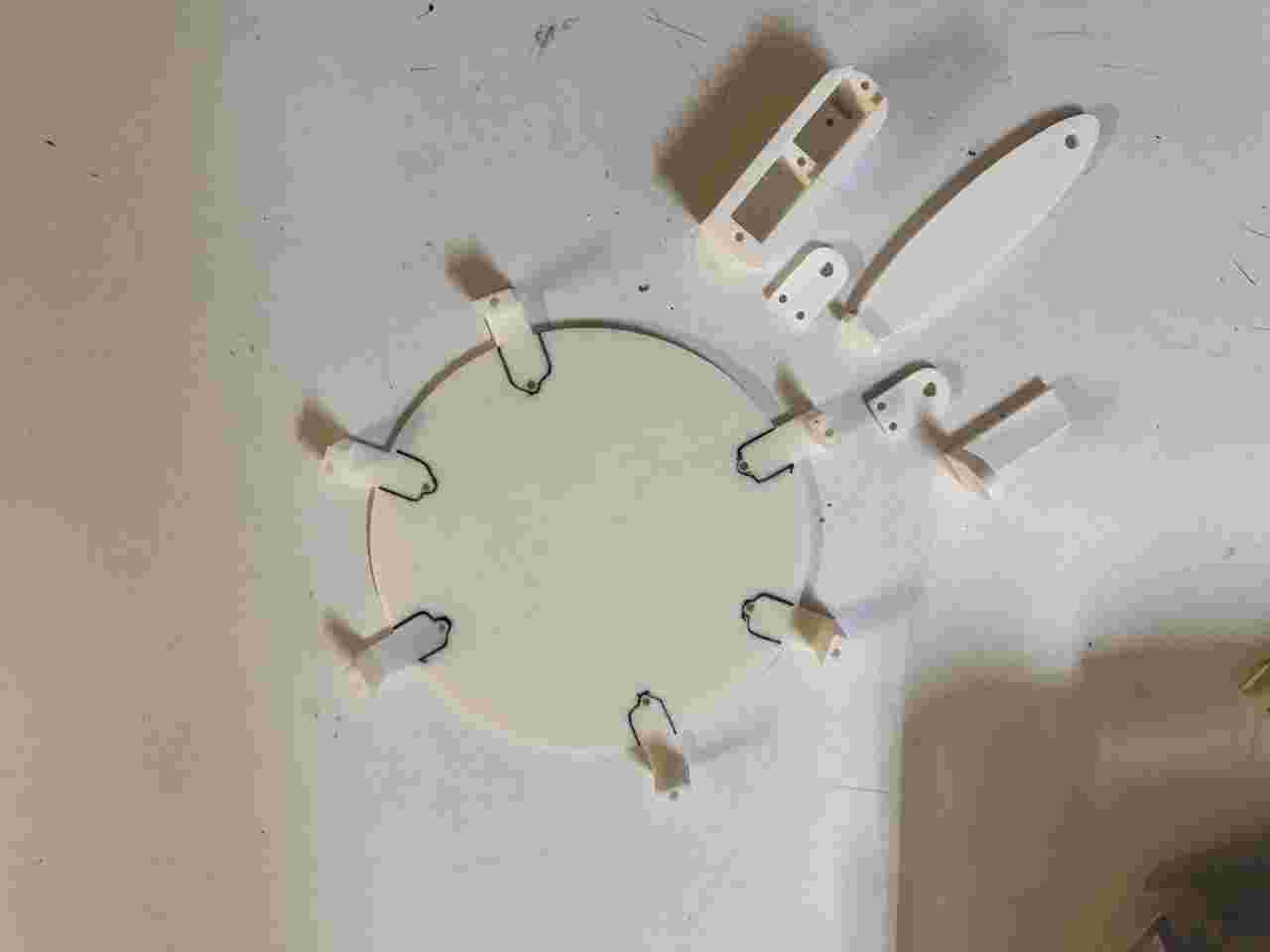
The body with the new modifications assembly looks like this.
2.8 Physycal assembly of the body V2
Here are almost all the pieces that has to be assemble.
Screw the servomotors of coxas to the body, use the M3 20mm screws.
Place the servo adapter on the servomotors allign them to 90 degrees with a code.
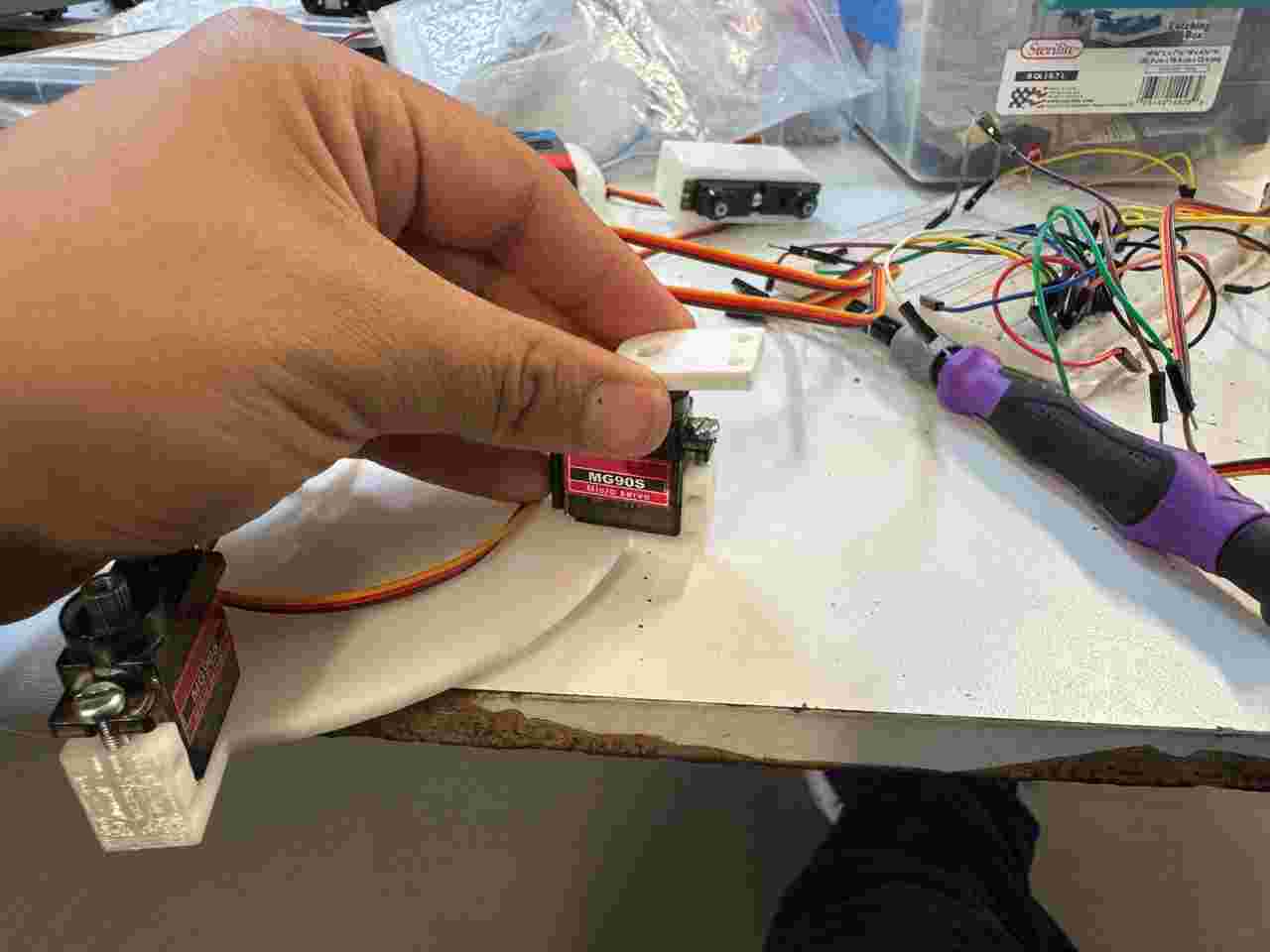
Screw the coxa-femur piece use the M3 5mm screws for the top and bottom (the part that joins this piece to the body) use the M3 12mm screws to create the rotation articulation.
Place 2 servomotors on the Caja femur V2 and use M3 20mm screws to screw them.
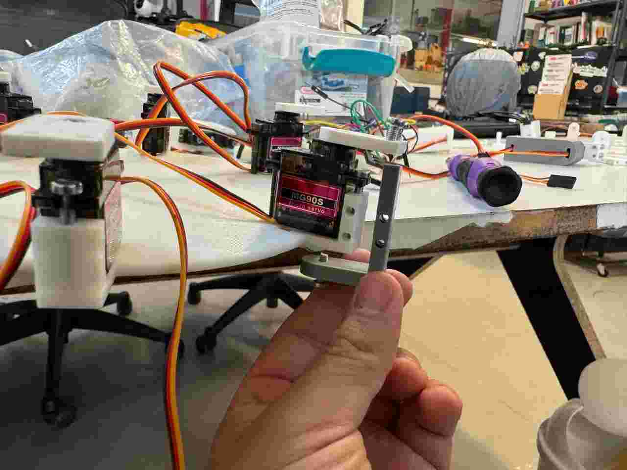
Place another servo adapter on the rounded part making sure that the servo is at 90 degrees. And screw it on the coxa-femur with the M3 12 mm screws.
Attach the Tibia V2 to the other servomotor.
Here is how all the assembly should look before placing the pther tibia.
Screw the M3.5 51mm screw on the hole near to the flat side of the already placed tibia, then screw the new tibia on the final side of the screw and for last screw the M5 10mm screws to screw the tibia V2 and the caja femur V2 together to make the rotational joint.
The last calibration to get the ideal form of our spiderbot is to place the femur of the left side and right side to 120 and 60 degrees respectively and then move the gear of each servomotor again the left side and right side to 180 degrees and 0 degrees respectively.
4. Coding
The code section will be divided into two parts the movement and calibration of the routine, and the integration of the movement with the interface created during week 14.
4.1 Motion code
I created several codes, such as the I2C detector and moving servos with the serial monitor, which I used to test the functionality of each module and servo motor.
I2C detector
          #include <Wire.h>

          void setup() {
            // Inicializa la comunicación serie a 115200 baudios
            Serial.begin(115200);
            while (!Serial) {
              delay(10); // Espera a que se abra el monitor serie (crucial para placas nativas USB como XIAO)
            }

            Serial.println("\n--- Escáner I2C para XIAO ---");

            // Inicializa el bus I2C
            Wire.begin();
          }

          void loop() {
            byte error, address;
            int nDevices;

            Serial.println("Escaneando bus I2C...");

            nDevices = 0;
            // El rango de direcciones I2C estándar va de 1 a 127
            for (address = 1; address < 127; address++) {

              // El protocolo inicia una transmisión a la dirección asignada
              Wire.beginTransmission(address);
              error = Wire.endTransmission();

              if (error == 0) {
                Serial.print("¡Dispositivo encontrado en la dirección 0x");
                if (address < 16) {
                  Serial.print("0");
                }
                Serial.print(address, HEX);
                Serial.println(" !");

                nDevices++;
              }
              else if (error == 4) {
                Serial.print("Error desconocido en la dirección 0x");
                if (address < 16) {
                  Serial.print("0");
                }
                Serial.println(address, HEX);
              }
            }

            if (nDevices == 0) {
              Serial.println("No se encontraron dispositivos I2C.\n");
            } else {
              Serial.println("Escaneo finalizado.\n");
            }

            // Espera 5 segundos antes de realizar el siguiente escaneo
            delay(5000);
          }
Move servos though the serial monitor
          #include <Wire.h>
          #include <Adafruit_PWMServoDriver.h>

          // Direcciones de cada módulo (A0 soldado = 0x41)
          Adafruit_PWMServoDriver pwmIzquierdo = Adafruit_PWMServoDriver(0x40);
          Adafruit_PWMServoDriver pwmDerecho   = Adafruit_PWMServoDriver(0x41);

          #define SERVOMIN  130
          #define SERVOMAX  610
          #define FREQUENCY 60

          void setup() {
            Serial.begin(115200);

            // Esperar a que el monitor serie abra (útil para la XIAO)+++
            while(!Serial) { delay(10); }


            // Inicializar I2C con velocidad rápida
            Wire.begin();
            //Wire.setClock(400000);//++++

            // Inicializar módulo Izquierdo (0x40)
            pwmIzquierdo.begin();
            pwmIzquierdo.setPWMFreq(FREQUENCY);

            // Inicializar módulo Derecho (0x41)
            pwmDerecho.begin();
            pwmDerecho.setPWMFreq(FREQUENCY);
            delay(50);//+++
            // Inicializar módulo Derecho (0x41)+++
            pwmDerecho.begin();
            pwmDerecho.setPWMFreq(FREQUENCY);

            delay(50); // <-- Pequeña pausa para estabilizar el oscilador

            //++++++++++
            Serial.println("Control Dual PCA9685 - Spiderbot listo");
            Serial.println("Formato: modulo,canal,grados (ej. 0,4,90 o 1,11,180)");
          }

          void loop() {
            if (Serial.available() > 0) {
              // Leer la línea completa hasta el salto de línea
              String entrada = Serial.readStringUntil('\n');
              entrada.trim(); // Eliminar espacios o caracteres raros al inicio/final

              if (entrada.length() > 0) {
                int primerComa = entrada.indexOf(',');
                int segundaComa = entrada.indexOf(',', primerComa + 1);

                // Validar que la cadena tenga la estructura correcta con dos comas
                if (primerComa != -1 && segundaComa != -1) {
                  int modulo = entrada.substring(0, primerComa).toInt();
                  int canal = entrada.substring(primerComa + 1, segundaComa).toInt();
                  int grados = entrada.substring(segundaComa + 1).toInt();

                  // Restringir los grados para proteger los servos
                  grados = constrain(grados, 0, 180);
                  int pulso = map(grados, 0, 180, SERVOMIN, SERVOMAX);

                  if (modulo == 0) {
                    pwmIzquierdo.setPWM(canal, 0, pulso);
                    Serial.print("[Módulo Izquierdo 0x40] -> ");
                  } else if (modulo == 1) {
                    pwmDerecho.setPWM(canal, 0, pulso);
                    Serial.print("[Módulo Derecho 0x41] -> ");
                  } else {
                    Serial.println("Error: Módulo no válido (usa 0 o 1)");
                    return;
                  }

                  Serial.print("Canal: "); Serial.print(canal);
                  Serial.print(" | Ángulo: "); Serial.print(grados);
                  Serial.println("°");
                } else {
                  Serial.println("Error de formato. Usa: modulo,canal,grados");
                }
              }
            }
          }
Calibrate the servos with this positions.
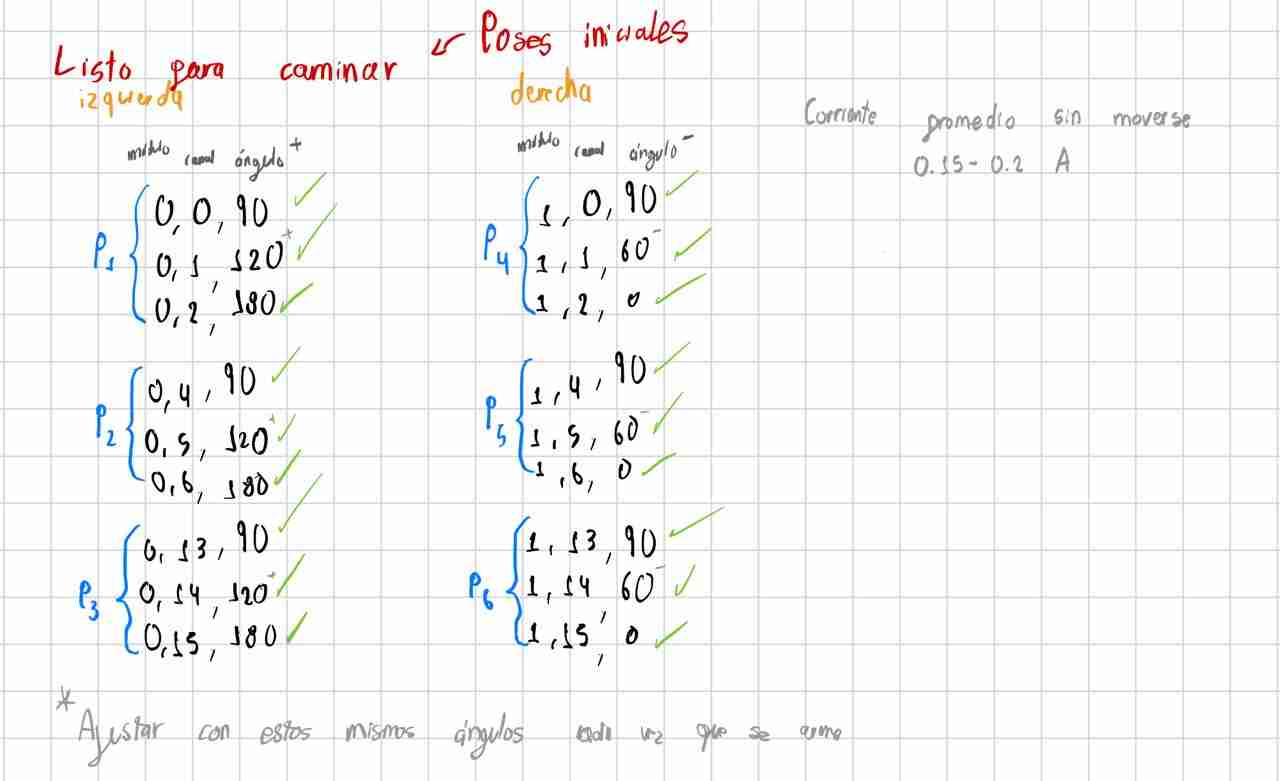
After I calibrate the servomotors with this code I moved to the routine that the spiderbot should do. While researching, I found the Jakob Leander channel which gave me the key to doing the routine, as it mentions that the support movement is called tripod gate, in which 3 legs must be in contact with the floor while the other 3 are above.
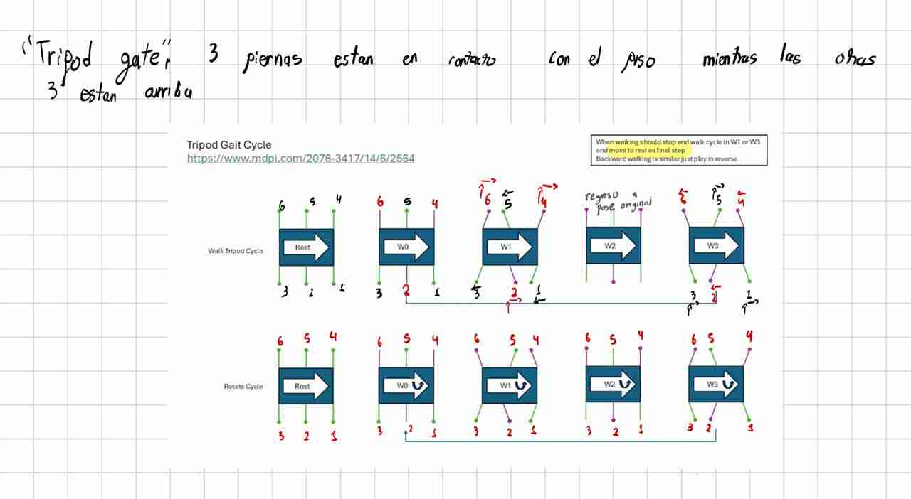
I tried implementing several routines without knowing about the tripod gate, and they didn't work because at some point only two legs were touching, or the movements were simply incorrect, causing the dog to not walk or to fall very easily. So, you're free to implement whatever routine you want, but I highly recommend going straight to the tripod gate.
With this in mind, and after playing around with the servo positions, I was able to arrive at this routine which mimics the previous image of the tripod gate with my legs.
Although manually moving the legs might work perfectly, when implementing it in a routine it won't work the first time, and the main reason is the synchronization of movements and steps, since sometimes it does the routine faster or performs steps before we want, so we have to keep modifying the instruction and function until we achieve the goal.
I noticed that if I gave the spiderbot a little help, it could walk, although it still fell off its legs 3 and 6. The critical stability problem occurs during the support exchange: if the incoming leg hasn't firmly planted itself on the ground before the supporting leg lifts off, the robot remains suspended for a few milliseconds, and gravity takes over.
In hexapod robotics, this adjustment is known as Overlap Support. To correct it, we must break the strict "Simultaneous" concept in Steps 2 and 3, and divide them into sub-steps where the golden rule is: First, plant the incoming leg firmly on the ground, secure its support, and then lift the other leg.
4.1 Making the code
4.1.1 Defining libraries, objects and constants
| Command / Element | Function |
|---|---|
| #include <Wire.h> | Standard library for I2C communication, used to talk to both PCA9685 modules. |
| #include <Adafruit_PWMServoDriver.h> | Library that handles the register configurations and pulse generation for the PCA9685 chips. |
| Adafruit_PWMServoDriver pwmDerecho(0x40) Adafruit_PWMServoDriver pwmIzquierdo(0x41) |
Creates two distinct objects representing each physical driver. One handles the right side of the robot (address 0x40) and the other the left side (address 0x41, with hardware address pin A0 soldered). |
| SERVOMIN, SERVOMAX, FREQUENCY | Defines the calibrated pulse limits (130 to 610) mapped to typical 0° to 180° movements, and establishes a 60Hz update rate standard for these servos. |
| COXA_CENTRO, COXA_ATR, COXA_ADE | Parametrizations for the physical travel limits of the coxa joints (Right and Left sides separated) to calibrate center, push (backwards), and swing (forward) phases cleanly. |
4.1.2 Setup and Bus Configuration
| Command | Function |
|---|---|
| Serial.setTimeout(50) | Configures a strict 50ms maximum wait time for incoming serial data, preventing the main loop from stuttering while parsing commands. |
| Wire.setClock(400000) | Forces the I2C communication bus to run in Fast Mode (400 kHz), allowing rapid angle updates for all 18 servos without communication bottlenecks. |
| begin() && setPWMFreq(FREQUENCY) | Initializes the internal oscillators of both PCA9685 modules and sets them to synchronized PWM generation frequencies. |
4.1.3 Serial Interface and Command Parsing
| Command | Function |
|---|---|
| Serial.readStringUntil('\n') | Captures the full execution buffer sent from the computer interface as an entire string until a line break is found. |
| comando.trim().toUpperCase() | Cleans up hidden spaces/returns and converts characters to uppercase to make the command triggers (M1, M2, S, INICIAR) case-insensitive. |
| procesarComandoManual(comando) | A fallback parser that splits comma-separated values (module, channel, degrees) using string manipulation if the user wants individual servo control. |
4.1.4 Servo Translation and Safety Helpers
| Command | Function |
|---|---|
| moverServo(modulo, canal, grados) | Abstraction function that determines which PCA9685 driver object to call depending on the active side (0 or 1), maps the degrees to a raw timing pulse, and commits the instruction. |
| map(grados, 0, 180, SERVOMIN, SERVOMAX) | Transforms real-world angle vectors (0° to 180°) into raw 12-bit duty cycle values understandable by the hardware registers. |
| esperarYRevisar(tiempoEspera) | A critical non-blocking time manager. It acts as a safety-conscious alternative to standard delay(), letting gaits transition smoothly while actively checking for abort triggers. |
| Serial.peek() | Inspects the incoming serial queue without consuming the data. It checks instantly if an emergency stop flag ('S') was sent, allowing a gait loop to terminate instantly mid-motion. |
4.1.5 Locomotion Sequences (Tripod Gait)
| Function | Function |
|---|---|
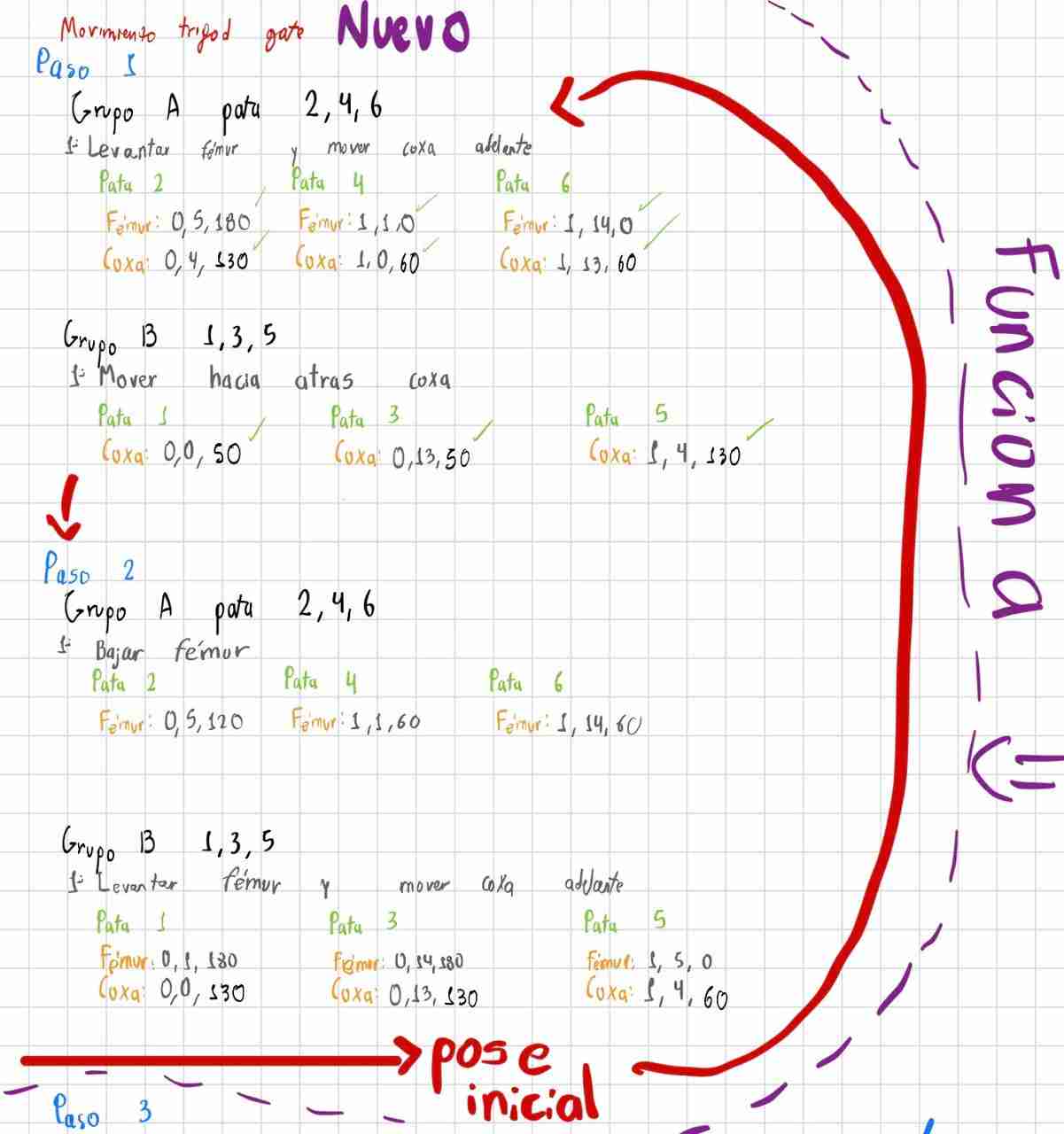
| poseInicial() | Commands all 18 servos to a structural baseline state. It sets the fémur and tibia steps to stable balancing thresholds while centering all six coxas. |
| paso1_Tripode(), paso2_Tripode(), paso3_Tripode() | The structural execution steps of a tripod gait. They alternate actions between structural Group A (legs 2, 4, 6) and Group B (legs 1, 3, 5), managing lifting phases, ground traction pushes, and mid-air recoveries sequentially. |
| ejecutarTripodeVX() | Implements different state cycles. V1 runs continuous cycles, V2 returns cleanly to a home sequence after each loop, and V3 runs a tighter, aggressive sprint sequence. |
            #include <Wire.h>
            #include <Adafruit_PWMServoDriver.h>

            // Definimos las direcciones de cada módulo
            Adafruit_PWMServoDriver pwmDerecho = Adafruit_PWMServoDriver(0x40);   // Módulo 0 (Lado Derecho)
            Adafruit_PWMServoDriver pwmIzquierdo = Adafruit_PWMServoDriver(0x41); // Módulo 1 (Lado Izquierdo)

            #define SERVOMIN  130
            #define SERVOMAX  610
            #define FREQUENCY 60

            // =====================================================================================
            // CALIBRACIÓN DE ÁNGULOS PARA LAS COXAS
            // =====================================================================================
            // LADO DERECHO (Módulo 0 - Patas 1, 2, 3)
            const int COXA_CENTRO_D = 90;   // Pose inicial
            const int COXA_ATR_D    = 50;   // Ángulo cuando la pata va hacia ATRÁS (Empuje)
            const int COXA_ADE_D    = 130;  // Ángulo cuando la pata va hacia ADELANTE (En el aire)

            // LADO IZQUIERDO (Módulo 1 - Patas 4, 5, 6)
            const int COXA_CENTRO_I = 90;   // Pose inicial
            const int COXA_ATR_I    = 130;  // Ángulo cuando la pata va hacia ATRÁS (Empuje)
            const int COXA_ADE_I    = 60;   // Ángulo cuando la pata va hacia ADELANTE (En el aire)
            // =====================================================================================

            // Estados de marcha: 0=Detenido, 1=M1, 2=M2, 3=M3
            int modoMarcha = 0;
            int velocidadTransicion = 500;

            void setup() {
              Serial.begin(115200);
              Serial.setTimeout(50);

              Wire.begin();
              Wire.setClock(400000);

              pwmDerecho.begin();
              pwmDerecho.setPWMFreq(FREQUENCY);

              pwmIzquierdo.begin();
              pwmIzquierdo.setPWMFreq(FREQUENCY);

              Serial.println("Control Maestro Spiderbot - Sistema Parametrizado Listo");
              Serial.println("- Escribe 'iniciar' para Pose Inicial");
              Serial.println("- Escribe 'M1' para Marcha Trípode V1");
              Serial.println("- Escribe 'M2' para Marcha Trípode V2 (Ciclo con regreso a inicio)");
              Serial.println("- Escribe 'M3' para Marcha Trípode V3 (Ciclo corto)");
              Serial.println("- Escribe 'S'  para detener y volver a Pose Inicial");
              Serial.println("- Formato manual: modulo,canal,grados (ej. 0,0,90)");
            }

            void loop() {
              if (Serial.available() > 0) {
                String comando = Serial.readStringUntil('\n');
                comando.trim();
                comando.toUpperCase();

                if (comando == "INICIAR") {
                  modoMarcha = 0;
                  Serial.println("Ejecutando: POSE INICIAL");
                  poseInicial();
                }
                else if (comando == "M1") {
                  modoMarcha = 1;
                  Serial.println("Ejecutando: TRIPODE V1");
                }
                else if (comando == "M2") {
                  modoMarcha = 2;
                  Serial.println("Ejecutando: TRIPODE V2");
                }
                else if (comando == "M3") {
                  modoMarcha = 3;
                  Serial.println("Ejecutando: TRIPODE V3");
                }
                else if (comando == "S") {
                  modoMarcha = 0;
                  Serial.println("Ejecutando: ALTO TOTAL Y REGRESO A POSE INICIAL");
                  poseInicial();
                }
                else if (comando.indexOf(',') > 0) {
                  procesarComandoManual(comando);
                }
              }

              if (modoMarcha == 1)      ejecutarTripodeV1();
              else if (modoMarcha == 2) ejecutarTripodeV2();
              else if (modoMarcha == 3) ejecutarTripodeV3();
            }

            void moverServo(int modulo, int canal, int grados) {
              int pulso = map(grados, 0, 180, SERVOMIN, SERVOMAX);
              if (modulo == 0) pwmDerecho.setPWM(canal, 0, pulso);
              else              pwmIzquierdo.setPWM(canal, 0, pulso);
            }

            void esperarYRevisar(int tiempoEspera) {
              unsigned long inicio = millis();
              while (millis() - inicio < tiempoEspera) {
                if (Serial.available() > 0) {
                  char c = Serial.peek();
                  if (c == 'S' || c == 's') {
                    modoMarcha = 0;
                    return;
                  }
                }
              }
            }

            void poseInicial() {
              // Fémures restaurados a tus valores estables originales (120 y 60)
              moverServo(0, 0, COXA_CENTRO_D); moverServo(0, 1, 120); moverServo(0, 2, 180); // P1
              moverServo(0, 4, COXA_CENTRO_D); moverServo(0, 5, 120); moverServo(0, 6, 180); // P2
              moverServo(0, 13, COXA_CENTRO_D); moverServo(0, 14, 120); moverServo(0, 15, 180); // P3

              moverServo(1, 0, COXA_CENTRO_I); moverServo(1, 1, 60);  moverServo(1, 2, 0);   // P4
              moverServo(1, 4, COXA_CENTRO_I); moverServo(1, 5, 60);  moverServo(1, 6, 0);   // P5
              moverServo(1, 13, COXA_CENTRO_I); moverServo(1, 14, 60); moverServo(1, 15, 0);  // P6
            }

            // ==========================================
            // PASOS ADAPTADOS A LAS NUEVAS VARIABLES
            // ==========================================

            void paso1_Tripode() {
              // SUB-TIEMPO 1.1: Levantar fémures Grupo A (2, 4, 6)
              moverServo(0, 5, 180);
              moverServo(1, 1, 0);
              moverServo(1, 14, 0);

              delay(100);

              // SUB-TIEMPO 1.2: Coxas Grupo A ADELANTE + Coxas Grupo B ATRÁS
              moverServo(0, 4, COXA_ADE_D);  // P2
              moverServo(1, 0, COXA_ADE_I);  // P4
              moverServo(1, 13, COXA_ADE_I); // P6

              moverServo(0, 0, COXA_ATR_D);   // P1
              moverServo(0, 13, COXA_ATR_D);  // P3
              moverServo(1, 4, COXA_ATR_I);   // P5
            }

            void paso2_Tripode() {
              // OBLIGACIÓN DE SOPORTE: Plantar Grupo A (2, 4, 6) al piso
              moverServo(0, 5, 120);
              moverServo(1, 1, 60);
              moverServo(1, 14, 60);

              delay(150);
              if (modoMarcha == 0) return;

              // Levantar fémures del Grupo B (1, 3, 5)
              moverServo(0, 1, 180);
              moverServo(0, 14, 180);
              moverServo(1, 5, 0);

              delay(80);

              // Avanzar coxas del Grupo B en el aire
              moverServo(0, 0, COXA_ADE_D);  // P1
              moverServo(0, 13, COXA_ADE_D); // P3
              moverServo(1, 4, COXA_ADE_I);  // P5
            }

            void paso3_Tripode() {
              // OBLIGACIÓN DE SOPORTE: Bajar Grupo B (1, 3, 5) al piso
              moverServo(0, 1, 120);
              moverServo(0, 14, 120);
              moverServo(1, 5, 60);

              delay(150);
              if (modoMarcha == 0) return;

              // Grupo A (2, 4, 6) ejecuta el empuje hacia atrás
              moverServo(0, 4, COXA_ATR_D);   // P2
              moverServo(1, 0, COXA_ATR_I);   // P4
              moverServo(1, 13, COXA_ATR_I);  // P6
            }

            // ==========================================
            // CONTROL DE CICLOS (M1, M2, M3)
            // ==========================================

            void ejecutarTripodeV1() {
              if (modoMarcha != 1) return;
              paso1_Tripode(); esperarYRevisar(velocidadTransicion);
              if (modoMarcha != 1) return;
              paso2_Tripode(); esperarYRevisar(velocidadTransicion);
              if (modoMarcha != 1) return;
              paso3_Tripode(); esperarYRevisar(velocidadTransicion);
            }

            void ejecutarTripodeV2() {
              if (modoMarcha != 2) return;
              paso1_Tripode(); esperarYRevisar(velocidadTransicion);
              if (modoMarcha != 2) return;
              paso2_Tripode(); esperarYRevisar(velocidadTransicion);
              if (modoMarcha != 2) return;
              paso3_Tripode(); esperarYRevisar(velocidadTransicion);
              if (modoMarcha != 2) return;
              poseInicial();   esperarYRevisar(velocidadTransicion);
            }

            void ejecutarTripodeV3() {
              if (modoMarcha != 3) return;
              paso1_Tripode(); esperarYRevisar(velocidadTransicion);
              if (modoMarcha != 3) return;
              paso2_Tripode(); esperarYRevisar(velocidadTransicion);

              if (modoMarcha != 3) return;
              moverServo(0, 1, 120); moverServo(0, 14, 120); moverServo(1, 5, 60); // Soporte Grupo B
              delay(150);

              if (modoMarcha != 3) return;
              poseInicial();   esperarYRevisar(velocidadTransicion);
            }

            void procesarComandoManual(String comando) {
              int primerComa = comando.indexOf(',');
              int segundaComa = comando.indexOf(',', primerComa + 1);
              if (primerComa > 0 && segundaComa > 0) {
                int modulo = comando.substring(0, primerComa).toInt();
                int canal = comando.substring(primerComa + 1, segundaComa).toInt();
                int grados = comando.substring(segundaComa + 1).toInt();

                moverServo(modulo, canal, grados);

                Serial.print("Manual -> Módulo "); Serial.print(modulo);
                Serial.print(" | Canal "); Serial.print(canal);
                Serial.print(" | Grados "); Serial.println(grados);
              } else {
                Serial.println("Error: Formato manual incorrecto. Usa modulo,canal,grados");
              }
            }
Now, modifying the velocidadTransicion variable, which is how long it takes to perform an action, I changed it from 1000ms to 300ms. This is the limit, because below that it does the routine too fast and therefore crashes.
Based on the routine of moving forward and using Gemini, describing what my code did and the behaviors it had, I managed to obtain walking backwards and rotating to both sides.
4.2 Complete motion
New functions.
4.2.1 Backward Tripod Gait (Reverse Mode)
| Function / Step | Mechanical Operation & Vector Inversion |
|---|---|
| paso1_Atras() | Lifts Group A (legs 2, 4, 6) into the air and swings their coxas to the rear limits (COXA_ATR). Simultaneously, Group B (legs 1, 3, 5) remains locked on the floor and pushes the chassis backward by driving towards their forward targets (COXA_ADE). |
| paso2_Atras() | Forces Group A back to the ground to secure traction. Immediately after, Group B lifts its fémures and shifts its coxas back to the rear starting limits (COXA_ATR) in mid-air to prepare for the subsequent push cycle. |
| ejecutarTripodeAtras() | The orchestration loop for modoMarcha == 4. It links the reverse steps sequentially, hooks into the non-blocking esperarYRevisar() handler for safety inputs, and returns the machine to a stable home pose upon stop commands. |
4.2.2 Axial Rotation (Clockwise & Counter-Clockwise)
| Function / Step | Asymmetric Vector Manipulation |
|---|---|
| paso1_RotarDerecha() paso2_RotarDerecha() |
Calculates a clockwise spin around the robot's center point. During the swing phase, the right side coxas move backward (COXA_ATR_D) while the left side coxas move forward (COXA_ADE_I), generating an asymmetrical rotational torque. |
| paso1_RotarIzquierda() paso2_RotarIzquierda() |
Calculates a counter-clockwise spin. It fully mirrors the angular vectors: right side coxas target the forward limits (COXA_ADE_D) while left side coxas swing toward their rear boundaries (COXA_ATR_I) in the air. |
4.2.3 Current Spikes Management (Micro-Staggering)
| Variable / Parameter | Dynamic Stabilization Effect |
|---|---|
| int delayPataPorPata = 40; | Establishes a critical 40ms hardware staggering interval inserted between individual servo write updates within every step sequence. |
| Electrical Purpose | Prevents the 18 servos from drawing inductive stall currents simultaneously. Staggering the startup loads protects the LiPo battery rail, eliminates logic brownouts on the microcontroller, and smooths out structural vibrations. |
Here is te complete motion code that will be integrated to the interface code.
            #include <Wire.h>
            #include <Adafruit_PWMServoDriver.h>

            Adafruit_PWMServoDriver pwmDerecho = Adafruit_PWMServoDriver(0x40);
            Adafruit_PWMServoDriver pwmIzquierdo = Adafruit_PWMServoDriver(0x41);

            #define SERVOMIN  130
            #define SERVOMAX  610
            #define FREQUENCY 60

            // =====================================================================================
            // ÁNGULOS PARAMETRIZADOS DE HOJA DE CALIBRACIÓN
            // =====================================================================================
            const int COXA_CENTRO_D = 90;
            const int COXA_ATR_D    = 50;   // Atrás
            const int COXA_ADE_D    = 130;  // Adelante

            const int COXA_CENTRO_I = 90;
            const int COXA_ATR_I    = 130;  // Atrás
            const int COXA_ADE_I    = 60;   // Adelante
            // =====================================================================================

            // Estados de marcha: 0=Stop, 3=Adelante, 4=Atrás, 5=Rotar Derecha, 6=Rotar Izquierda
            int modoMarcha = 0;
            int velocidadTransicion = 300;
            int delayPataPorPata = 40;

            void setup() {
              Serial.begin(115200);
              Serial.setTimeout(50);

              Wire.begin();
              Wire.setClock(400000);

              pwmDerecho.begin();
              pwmDerecho.setPWMFreq(FREQUENCY);
              pwmIzquierdo.begin();
              pwmIzquierdo.setPWMFreq(FREQUENCY);

              Serial.println("--- Sistema Spiderbot: Navegación Completa ---");
              Serial.println("Comandos: INICIAR | M3 | ATRAS | ROTAR_DER | ROTAR_IZQ | S");
            }

            void loop() {
              if (Serial.available() > 0) {
                String comando = Serial.readStringUntil('\n');
                comando.trim();
                comando.toUpperCase();

                if (comando == "INICIAR") {
                  modoMarcha = 0;
                  Serial.println("[OK] Pose Inicial");
                  poseInicial();
                }
                else if (comando == "M3") { modoMarcha = 3; Serial.println("[OK] Marcha Adelante"); }
                else if (comando == "ATRAS") { modoMarcha = 4; Serial.println("[OK] Reversa"); }
                else if (comando == "ROTAR_DER") { modoMarcha = 5; Serial.println("[OK] Rotando Derecha --->"); }
                else if (comando == "ROTAR_IZQ") { modoMarcha = 6; Serial.println("[OK] Rotando Izquierda <---"); }
                else if (comando == "S") {
                  modoMarcha = 0;
                  Serial.println("[OK] Parada de Emergencia");
                  poseInicial();
                }
                else if (comando.indexOf(',') > 0) {
                  procesarComandoManual(comando);
                }
              }

              // Máquina de estados continua
              if (modoMarcha == 3)      ejecutarTripodeM3();
              else if (modoMarcha == 4) ejecutarTripodeAtras();
              else if (modoMarcha == 5) ejecutarRotarDerecha();
              else if (modoMarcha == 6) ejecutarRotarIzquierda();
            }

            void moverServo(int modulo, int canal, int grados) {
              int pulso = map(grados, 0, 180, SERVOMIN, SERVOMAX);
              if (modulo == 0) pwmDerecho.setPWM(canal, 0, pulso);
              else              pwmIzquierdo.setPWM(canal, 0, pulso);
            }

            void esperarYRevisar(int tiempoEspera) {
              unsigned long inicio = millis();
              while (millis() - inicio < tiempoEspera) {
                if (Serial.available() > 0) {
                  char c = Serial.peek();
                  if (c == 'S' || c == 's' || c == 'I' || c == 'i') return;
                }
              }
            }

            void poseInicial() {
              moverServo(0, 0, COXA_CENTRO_D); moverServo(0, 1, 120); moverServo(0, 2, 180); // P1
              moverServo(0, 4, COXA_CENTRO_D); moverServo(0, 5, 120); moverServo(0, 6, 180); // P2
              moverServo(0, 13, COXA_CENTRO_D); moverServo(0, 14, 120); moverServo(0, 15, 180); // P3

              moverServo(1, 0, COXA_CENTRO_I); moverServo(1, 1, 60);  moverServo(1, 2, 0);   // P4
              moverServo(1, 4, COXA_CENTRO_I); moverServo(1, 5, 60);  moverServo(1, 6, 0);   // P5
              moverServo(1, 13, COXA_CENTRO_I); moverServo(1, 14, 60); moverServo(1, 15, 0);  // P6
            }

            // ==========================================================================
            // RUTA: ADELANTE (M3) Y ATRÁS (ATRAS) COMPILADAS CORECTAMENTE
            // ==========================================================================

            void paso1_Adelante() {
              moverServo(0, 5, 180); moverServo(0, 4, COXA_ADE_D);  delay(delayPataPorPata);
              moverServo(1, 1, 0);   moverServo(1, 0, COXA_ADE_I);  delay(delayPataPorPata);
              moverServo(1, 14, 0);  moverServo(1, 13, COXA_ADE_I); delay(delayPataPorPata);
              moverServo(0, 0, COXA_ATR_D);  delay(delayPataPorPata);
              moverServo(0, 13, COXA_ATR_D); delay(delayPataPorPata);
              moverServo(1, 4, COXA_ATR_I);  delay(delayPataPorPata);
            }

            void paso2_Adelante() {
              moverServo(0, 5, 120);  delay(delayPataPorPata);
              moverServo(1, 1, 60);   delay(delayPataPorPata);
              moverServo(1, 14, 60);  delay(delayPataPorPata);
              delay(120); if (modoMarcha != 3) return;
              moverServo(0, 1, 180); moverServo(0, 0, COXA_ADE_D);  delay(delayPataPorPata);
              moverServo(0, 14, 180); moverServo(0, 13, COXA_ADE_D); delay(delayPataPorPata);
              moverServo(1, 5, 0);   moverServo(1, 4, COXA_ADE_I);  delay(delayPataPorPata);
            }

            void ejecutarTripodeM3() {
              if (modoMarcha != 3) return; paso1_Adelante(); esperarYRevisar(velocidadTransicion);
              if (modoMarcha != 3) return; paso2_Adelante(); esperarYRevisar(velocidadTransicion);
              if (modoMarcha != 3) return; moverServo(0, 1, 120); moverServo(0, 14, 120); moverServo(1, 5, 60); delay(150);
              if (modoMarcha != 3) return; poseInicial(); esperarYRevisar(velocidadTransicion);
            }

            void paso1_Atras() {
              moverServo(0, 5, 180); moverServo(0, 4, COXA_ATR_D);  delay(delayPataPorPata);
              moverServo(1, 1, 0);   moverServo(1, 0, COXA_ATR_I);  delay(delayPataPorPata);
              moverServo(1, 14, 0);  moverServo(1, 13, COXA_ATR_I); delay(delayPataPorPata);
              moverServo(0, 0, COXA_ADE_D);  delay(delayPataPorPata);
              moverServo(0, 13, COXA_ADE_D); delay(delayPataPorPata);
              moverServo(1, 4, COXA_ADE_I);  delay(delayPataPorPata);
            }

            void paso2_Atras() {
              moverServo(0, 5, 120);  delay(delayPataPorPata);
              moverServo(1, 1, 60);   delay(delayPataPorPata);
              moverServo(1, 14, 60);  delay(delayPataPorPata);
              delay(120); if (modoMarcha != 4) return;
              moverServo(0, 1, 180); moverServo(0, 0, COXA_ATR_D);  delay(delayPataPorPata);
              moverServo(0, 14, 180); moverServo(0, 13, COXA_ATR_D); delay(delayPataPorPata);
              moverServo(1, 5, 0);   moverServo(1, 4, COXA_ATR_I);  delay(delayPataPorPata);
            }

            void ejecutarTripodeAtras() {
              if (modoMarcha != 4) return; paso1_Atras(); esperarYRevisar(velocidadTransicion);
              if (modoMarcha != 4) return; paso2_Atras(); esperarYRevisar(velocidadTransicion);
              if (modoMarcha != 4) return; moverServo(0, 1, 120); moverServo(0, 14, 120); moverServo(1, 5, 60); delay(150);
              if (modoMarcha != 4) return; poseInicial(); esperarYRevisar(velocidadTransicion);
            }

            // ==========================================================================
            // RUTA NUEVA: ROTAR A LA DERECHA (Sincronizado Pata por Pata)
            // ==========================================================================

            void paso1_RotarDerecha() {
              // Grupo A (2, 4, 6) al AIRE: Coxa Derecha va ATRÁS, Coxas Izquierdas van ADELANTE
              moverServo(0, 5, 180); moverServo(0, 4, COXA_ATR_D);  delay(delayPataPorPata); // P2 (D)
              moverServo(1, 1, 0);   moverServo(1, 0, COXA_ADE_I);  delay(delayPataPorPata); // P4 (I)
              moverServo(1, 14, 0);  moverServo(1, 13, COXA_ADE_I); delay(delayPataPorPata); // P6 (I)

              // Grupo B (1, 3, 5) al PISO EMPUJA: Coxas Derechas ADELANTE, Coxa Izquierda ATRÁS
              moverServo(0, 0, COXA_ADE_D);  delay(delayPataPorPata); // P1 (D)
              moverServo(0, 13, COXA_ADE_D); delay(delayPataPorPata); // P3 (D)
              moverServo(1, 4, COXA_ATR_I);  delay(delayPataPorPata); // P5 (I)
            }

            void paso2_RotarDerecha() {
              // Grupo A (2, 4, 6) baja de vuelta al piso
              moverServo(0, 5, 120);  delay(delayPataPorPata);
              moverServo(1, 1, 60);   delay(delayPataPorPata);
              moverServo(1, 14, 60);  delay(delayPataPorPata);

              delay(120); if (modoMarcha != 5) return;

              // Grupo B (1, 3, 5) al AIRE: Coxas Derechas van ATRÁS, Coxa Izquierda va ADELANTE
              moverServo(0, 1, 180); moverServo(0, 0, COXA_ATR_D);  delay(delayPataPorPata); // P1 (D)
              moverServo(0, 14, 180); moverServo(0, 13, COXA_ATR_D); delay(delayPataPorPata); // P3 (D)
              moverServo(1, 5, 0);   moverServo(1, 4, COXA_ADE_I);  delay(delayPataPorPata); // P5 (I)
            }

            void ejecutarRotarDerecha() {
              if (modoMarcha != 5) return; paso1_RotarDerecha(); esperarYRevisar(velocidadTransicion);
              if (modoMarcha != 5) return; paso2_RotarDerecha(); esperarYRevisar(velocidadTransicion);
              if (modoMarcha != 5) return; moverServo(0, 1, 120); moverServo(0, 14, 120); moverServo(1, 5, 60); delay(150);
              if (modoMarcha != 5) return; poseInicial(); esperarYRevisar(velocidadTransicion);
            }

            // ==========================================================================
            // RUTA NUEVA: ROTAR A LA IZQUIERDA (Inversión total de coxas)
            // ==========================================================================

            void paso1_RotarIzquierda() {
              // Grupo A (2, 4, 6) al AIRE: Coxa Derecha va ADELANTE, Coxas Izquierdas van ATRÁS
              moverServo(0, 5, 180); moverServo(0, 4, COXA_ADE_D);  delay(delayPataPorPata); // P2 (D)
              moverServo(1, 1, 0);   moverServo(1, 0, COXA_ATR_I);  delay(delayPataPorPata); // P4 (I)
              moverServo(1, 14, 0);  moverServo(1, 13, COXA_ATR_I); delay(delayPataPorPata); // P6 (I)

              // Grupo B (1, 3, 5) al PISO EMPUJA: Coxas Derechas ATRÁS, Coxa Izquierda ADELANTE
              moverServo(0, 0, COXA_ATR_D);  delay(delayPataPorPata); // P1 (D)
              moverServo(0, 13, COXA_ATR_D); delay(delayPataPorPata); // P3 (D)
              moverServo(1, 4, COXA_ADE_I);  delay(delayPataPorPata); // P5 (I)
            }

            void paso2_RotarIzquierda() {
              // Grupo A (2, 4, 6) baja al piso
              moverServo(0, 5, 120);  delay(delayPataPorPata);
              moverServo(1, 1, 60);   delay(delayPataPorPata);
              moverServo(1, 14, 60);  delay(delayPataPorPata);

              delay(120); if (modoMarcha != 6) return;

              // Grupo B (1, 3, 5) al AIRE: Coxas Derechas van ADELANTE, Coxa Izquierda va ATRÁS
              moverServo(0, 1, 180); moverServo(0, 0, COXA_ADE_D);  delay(delayPataPorPata); // P1 (D)
              moverServo(0, 14, 180); moverServo(0, 13, COXA_ADE_D); delay(delayPataPorPata); // P3 (D)
              moverServo(1, 5, 0);   moverServo(1, 4, COXA_ATR_I);  delay(delayPataPorPata); // P5 (I)
            }

            void ejecutarRotarIzquierda() {
              if (modoMarcha != 6) return; paso1_RotarIzquierda(); esperarYRevisar(velocidadTransicion);
              if (modoMarcha != 6) return; paso2_RotarIzquierda(); esperarYRevisar(velocidadTransicion);
              if (modoMarcha != 6) return; moverServo(0, 1, 120); moverServo(0, 14, 120); moverServo(1, 5, 60); delay(150);
              if (modoMarcha != 6) return; poseInicial(); esperarYRevisar(velocidadTransicion);
            }

            // ==========================================
            // PARSEO MANUAL
            // ==========================================
            void procesarComandoManual(String comando) {
              int primerComa = comando.indexOf(',');
              int segundaComa = comando.indexOf(',', primerComa + 1);
              if (primerComa > 0 && segundaComa > 0) {
                int modulo = comando.substring(0, primerComa).toInt();
                int canal = comando.substring(primerComa + 1, segundaComa).toInt();
                int grados = comando.substring(segundaComa + 1).toInt();
                moverServo(modulo, canal, grados);
              }
            }
4.3 Interface code
This code is the same that I used during week 14 the changes will be that they will have the code we just made to integrate the movement and the buttons will be replaced by joysticks, in addition to adding an emergency stop in case the spiderbot gets stuck and cannot return to its initial position so that it returns to that pose.
4.3.1 Modifications to the previous code and how the complete code works before integrating the flight sensors
When I did my tests and didn't design the final board (my bad), I spent an hour and a half trying to solve a communication problem because supposedly my interface was made to only add the spiderbot movement part, but when I did this my page wouldn't load.
Upon investigation, I discovered that the flight sensors were responsible for the loading issue because the VL53L0X library uses blocking functions by default. With nothing connected, the `readRangeSingleMillimeters()` function waits for a response from the sensor that never arrives. Since the processor is stuck trying to read the sensor, it never executes `server.handleClient()`, causing my iPhone to load the interface page indefinitely until it times out.
That's why there will be two codes: one without the flight sensors so we can test everything else, and the final one which will include them.
Hardware Infrastructure & Global Calibration Settings
| Parameter / Object | Functional Specifications & Resource Allocation |
|---|---|
const char* ssid / password |
Stores network authentication credentials securely. Configures the ESP32-C6 to hook into local access points using high-throughput Wi-Fi layers. |
WebServer server(80); |
Instantiates the synchronous HTTP server on standard port 80, specifically dedicated to streaming the compiled base web template during client handshake requests. |
WebSocketsServer webSocket(81); |
Mounts an asynchronous, persistent TCP control channel on port 81. It strips standard HTTP packaging overhead to deliver teleoperation data packet streams with sub-10ms response latencies. |
pwmDerecho (0x40) |
Initializes dual Adafruit PCA9685 I2C driver instances. They expand hardware resources to achieve independent 12-bit resolution control over all 18 structural servos. |
#define SERVOMIN 130 |
Establishes safe structural boundaries mapping 0° to 180° angular vectors into raw hardware PWM pulse counts, protecting internal gear assemblies from binding. |
#define FREQUENCY 60 |
Forces the PCA9685 output channels to operate at a stable 60Hz update rate, matching the optimal refresh cycle required by high-torque analog/digital servo motors. |
const int PIN_BUZZER = 20; |
Maps physical GPIO 20 as a direct hardware-driven output pathway to feed audio frequencies into the onboard acoustic signaling device. |
COXA_CENTRO_D = 90; |
Defines baseline angular offsets for the right and left coxa joints. Ensures geometric symmetry across all lateral axes during neutral calibration initialization. |
int joyX = 0; |
Global runtime registers that buffer the most recent horizontal and vertical displacement vectors decoded from client teleoperation streams. |
int velocidadTransicion = 300; |
Sets the base timing constraint (in milliseconds) used to scale interpolation speeds between active structural push phases. |
int delayPataPorPata = 40; |
Establishes a critical hardware-staggering interval. Delays sequential servo updates by 40ms to flatten current spikes and eliminate logic brownouts on the LiPo rail. |
bool panicTriggered = false; |
Emergency stop binary flag. When raised, it instantly forces execution routines to dump active gait sequences and return to home coordinates. |
bool estaEnPoseInicial = false; |
State variable tracking current posture configurations. Prevents execution loops from flooding the I2C bus with redundant home-pose servo write commands. |
int contadorSonido = 0; |
An integer step-index register tracking the active audio mode cycle to route sequential acoustic feedback alerts correctly. |
Monolithic Embedded UI Asset & Client Logic
| Asset Module / Script Block | Client-Side Layout Execution & Teleoperation Constraints |
|---|---|
PROGMEM interfaz_html[] |
Stores the complete raw HTML/CSS/JS interface string directly inside non-volatile Flash memory space, preserving critical SRAM allocations for runtime operations. |
CSS Spidey Grid Layout |
Builds a responsive web layout running via 3-column, 3-row CSS Grid systems. Fixes viewport limits to 100vw/100vh, uses translucent backdrops (rgba(255,255,255,0.1)), and forces a custom red-to-blue linear Spidey gradient. |
initApp() Function |
Orchestrates client-side startup operations: hooks the camera view pane into the dedicated ESP32-S3 MJPEG stream URL (port 81) and opens a live WebSocket handshake with the ESP32-C6. |
setupSingleJoystick() |
Monitors screen touch boundaries using specialized EventListeners. It computes real-time touch displacements, normalizes input fields against a max 35px tracking radius, and maps outputs to +/-100 integer ranges. |
sendJoystickData(bool force) |
A smart data transmission regulator. Uses a 50ms time-delta gate to prevent network flood bottlenecks while forcing instant updates when joysticks clear back to neutral center axes (0,0). |
Asynchronous Protocol Parser & Acoustic State Machine
| Interrupt Event / Audio Case | Payload Extraction & Real-Time System Adjustments |
|---|---|
webSocketEvent() |
The primary network processing module. Intercepts incoming WebSocket text strings asynchronously and splits data streams based on string identifiers. |
"J,X,Y" Substring Decoder |
Scans for structural token commas within the raw character payload. Uses sequential index offsets to extract and parse string fragments into global joyX and joyY coordinate variables. |
Command "S" (Panic Stop) |
Intercepts the emergency halt payload. Instantly zeroes tracking coordinates, triggers the panicTriggered flag, and bypasses processing queues to run the poseInicial() safety reset. |
Acoustic Engine: Case 1 |
Executes the Trace-E signature greeting. Loops a fast tone-sweep ranging from 1600Hz to 2100Hz three times with precise 65ms rest windows between iterations. |
Acoustic Engine: Case 2 |
Generates the double-pulsed Trace-E warning alert. Sequences fixed tone intervals at 1100Hz, 1150Hz, and 1300Hz split by micro-delay gaps to output a structured alert pattern. |
Acoustic Engine: Case 3 |
Simulates a system failure chime. Drives a descending pitch sweep from 2400Hz down to 500Hz in steps of 25Hz, modeling a dynamic power-down curve. |
Acoustic Engine: Case 4 |
Triggers an acute high-frequency chirp. Climbs quickly from 2500Hz to 3600Hz, concluding with an isolated 3800Hz sound blast to create a responsive, robotic chirp effect. |
Acoustic Engine: Case 5 |
Models the complex Jeff the Land Shark audio profile. Executes a fast low-frequency growl cycle (1700Hz to 1550Hz), takes a 40ms breather, and then drives a continuous rising howl up to 3400Hz before gently tapering off. |
Command "Q" (Mute) |
Acts as an audio-kill gate. Immediately invokes noTone() on GPIO 20 to isolate the piezo element and prevent speaker coil humming. |
Kinematic Mixing & Asymmetric Gait Execution
| Kinematic Routine Block | Mathematical Scaling & Phased Leg Transitions |
|---|---|
Deadzone Filter (+/-15) |
Evaluates raw inputs against a threshold window. If coordinate parameters sit within +/-15 units, it ignores noise artifacts and transitions the system back to its home state safely. |
Asymmetric Proportional Scaling |
Clamps max coordinate inputs to normalized float scales. Restricts corner limbs (Legs 1, 4, 3, 6) to a tight 16.0° amplitude envelope while granting middle joints (Legs 2, 5) a full 25.0° path to minimize leverage stress. |
swing_Px / pull_Px Mixer |
Calculates dynamic coxa profiles by mixing pitch (fY) and roll (fX) parameters via inline algebra. Blends directional translations with axial rotations seamlessly inside a single stride. |
Tripod 1 Swing Phase |
Fires targeted position commands to lift the fémures of Tripod 1 (Legs P2, P5, P6) to maximum clearance height. Staggers servo signals by delayPataPorPata to protect against current surges. |
Tripod 1 Extension & Push |
Drives the airborne coxas of Tripod 1 toward their swing coordinates. Simultaneously, it commands the grounded Tripod 2 (Legs P1, P3, P4) to complete an inversion sweep, driving structural weight forward. |
Tripod 1 Landing Core |
Lowers the airborne limbs back down to 120°/60° landing markers. Holds execution via a controlled 120ms landing window to ensure positive traction before shifting weight. |
Tripod 2 Swing Phase |
Mirrors the sequence by driving the fémures of Tripod 2 (Legs P1, P3, P4) into an elevated clearance altitude while tracking emergency exit checks at each step. |
Tripod 2 Extension & Push |
Pushes Tripod 2 forward through the air toward its targets while commanding the now-grounded Tripod 1 to execute its mechanical drive stroke. |
Tripod 2 Landing Core |
Returns Tripod 2 to the ground, restoring a stable posture across all 6 limbs before the master control loop re-evaluates the joystick input queues. |
Execution Core & Base Utility Modules
| Utility Function | Low-Level Routine Execution & Processing Control |
|---|---|
handleRoot() |
Triggers an HTTP response payload. Streams the monolithic interfaz_html asset string back to browsers with a 200/text/html response header. |
smartDelay(uint32_t ms) |
Replaces standard blocking delay loops. Uses a time-delta evaluation loop to continuously run background task handles (server.handleClient(), webSocket.loop()) while monitoring for sudden panic commands. |
moverServo() |
Accepts target channel positions and maps angular values linearly into calibrated PWM resolution registers, routing the data to the correct PCA9685 driver instance over the I2C bus. |
poseInicial() |
Hardcodes static angular coordinates directly across all 18 joints. Restores standard reference poses across all coxas, fémures, and tibias to return the platform to a stable baseline. |
setup() |
The initialization sequence. Mounts the high-speed Serial bus, initializes GPIO directions, configures the 400kHz I2C interface, triggers home configurations, establishes Wi-Fi, and binds network server callbacks. |
loop() |
The main background processing loop. Runs network client handlers, maintains live WebSocket connections, and continuously loops the dynamic kinematics matrix to drive the robot based on incoming control vectors. |
Here is the complete code por the control, remember that the code from the retransmission video is on week 14 or on the seed studio web page.
#include <WebSocketsServer.h>
#include <WebServer.h>
#include <Wire.h>
#include <Adafruit_PWMServoDriver.h>
const char* ssid = "Joseph";
const char* password = "abcdefgq";
// --- Hardware de Control ---
WebServer server(80);
WebSocketsServer webSocket = WebSocketsServer(81);
Adafruit_PWMServoDriver pwmDerecho = Adafruit_PWMServoDriver(0x40);
Adafruit_PWMServoDriver pwmIzquierdo = Adafruit_PWMServoDriver(0x41);
#define SERVOMIN 130
#define SERVOMAX 610
#define FREQUENCY 60
const int PIN_BUZZER = 20;
// --- Ángulos Parametrizados de Calibración ---
const int COXA_CENTRO_D = 90;
const int COXA_CENTRO_I = 90;
// --- Variables de Navegación Dinámica e Interrupción ---
int joyX = 0;
int joyY = 0;
int velocidadTransicion = 300;
int delayPataPorPata = 40;
bool panicTriggered = false; // Bandera de parada de emergencia
bool estaEnPoseInicial = false; // Evita saturar el bus I2C
int contadorSonido = 0;
// --- INTERFAZ WEB COMPLETA ---
const char interfaz_html[] PROGMEM = R"rawliteral(
<!DOCTYPE html>
<html lang="es">
<head>
<meta charset="UTF-8">
<meta name="viewport" content="width=device-width, initial-scale=1.0, maximum-scale=1.0, user-scalable=no, viewport-fit=cover">
<title>SpiderBot Spidey Control</title>
<meta name="apple-mobile-web-app-capable" content="yes">
<meta name="apple-mobile-web-app-status-bar-style" content="black-translucent">
<style>
:root {
--spidey-blue: #001f3f;
--spidey-red: #8b0000;
--glass: rgba(255, 255, 255, 0.1);
--vh: 1vh;
}
* { box-sizing: border-box; -webkit-tap-highlight-color: transparent; user-select: none; }
body {
margin: 0; padding: 0;
height: calc(var(--vh, 1vh) * 100);
width: 100vw; overflow: hidden;
font-family: system-ui, -apple-system, sans-serif;
background: linear-gradient(135deg, var(--spidey-blue), var(--spidey-red));
color: white;
}
#app-container {
display: grid;
grid-template-columns: 160px 1fr 160px;
grid-template-rows: 70px 1fr 70px;
height: 100%; width: 100%;
padding: 15px 30px; gap: 10px;
}
#camera-view {
grid-column: 1 / 4; grid-row: 1 / 4;
border: 2px solid rgba(255, 255, 255, 0.3);
background: #000; border-radius: 20px;
z-index: 1; overflow: hidden;
display: flex; justify-content: center; align-items: center;
}
#camera-view img { width: 100%; height: 100%; object-fit: cover; }
#connect-btn {
position: absolute; top: 20px; left: 50%; transform: translateX(-50%);
z-index: 100; padding: 10px 20px; border-radius: 25px;
background: #28a745; border: 2px solid white; color: white;
font-weight: bold; box-shadow: 0 4px 15px rgba(0,0,0,0.5);
transition: background 0.2s;
}
.panel {
z-index: 10;
background: var(--glass);
backdrop-filter: blur(8px);
-webkit-backdrop-filter: blur(8px);
border-radius: 25px;
display: flex; flex-direction: column; justify-content: center; align-items: center;
border: 1px solid rgba(255,255,255,0.2); padding: 10px;
}
.panel-left { grid-column: 1; grid-row: 2; }
.panel-right { grid-column: 3; grid-row: 2; }
.joy-container {
width: 120px; height: 120px;
background: rgba(255, 255, 255, 0.05);
border: 2px solid rgba(255,255,255,0.3);
border-radius: 50%; position: relative;
display: flex; justify-content: center; align-items: center;
}
.joy-handle {
width: 55px; height: 55px;
background: rgba(255, 255, 255, 0.9);
border-radius: 50%; position: absolute;
box-shadow: 0 4px 10px rgba(0,0,0,0.4);
}
.btn-action {
width: 55px; height: 55px; border-radius: 50%;
background: var(--glass); display: flex; justify-content: center; align-items: center;
font-size: 22px; z-index: 10; transition: background 0.2s, transform 0.1s;
border: 2px solid white;
}
.btn-action:active { background: rgba(255, 255, 255, 0.4); transform: scale(0.9); }
#stop-area { grid-column: 1; grid-row: 1; display: flex; justify-content: center; align-items: center; }
#buzzer-area { grid-column: 3; grid-row: 1; display: flex; justify-content: center; align-items: center; }
#rotation-overlay { display: none; position: fixed; top: 0; left: 0; width: 100%; height: 100%; background: #000; z-index: 9999; flex-direction: column; justify-content: center; align-items: center; text-align: center; }
@media (orientation: portrait) { #rotation-overlay { display: flex; } }
</style>
</head>
<body>
<div id="rotation-overlay"><h1>🔄 ROTAR DISPOSITIVO</h1><p>Activa el modo horizontal para el control Spidey.</p></div>
<button id="connect-btn" onclick="initApp()">CONECTAR SPIDERBOT</button>
<div id="app-container">
<div id="camera-view"><img id="stream-img" src="" alt="Esperando transmisión..."></div>
<div id="stop-area"><div class="btn-action" style="border-color: #ff4444; background: rgba(255,0,0,0.2);" ontouchstart="sendCmd('S')">✋</div></div>
<div class="panel panel-left">
<small style="margin-bottom:8px; font-weight:bold; letter-spacing: 1px;">ROTAR</small>
<div class="joy-container" id="joy-left-container"><div class="joy-handle" id="joy-left-handle"></div></div>
biographical
</div>
<div id="buzzer-area"><div class="btn-action" style="border-color: #007bff;" ontouchstart="sendCmd('B')" ontouchend="sendCmd('Q')">🔔</div></div>
<div class="panel panel-right">
<small style="margin-bottom:8px; font-weight:bold; letter-spacing: 1px;">MOVER</small>
<div class="joy-container" id="joy-right-container"><div class="joy-handle" id="joy-right-handle"></div></div>
</div>
</div>
<script>
let socket;
const IP_C6 = window.location.hostname;
const IP_S3 = "172.20.10.4"; // Tu IP fija verificada de la cámara
let joyLeftX = 0;
let joyRightY = 0;
function setDocHeight() { document.documentElement.style.setProperty('--vh', `${window.innerHeight * 0.01}px`); }
window.addEventListener('resize', setDocHeight); setDocHeight();
function initApp() {
document.getElementById('stream-img').src = `http://${IP_S3}:81/stream`;
socket = new WebSocket(`ws://${IP_C6}:81`);
socket.onopen = () => { const btn = document.getElementById('connect-btn'); btn.innerText = "CONECTADO"; btn.style.background = "#007bff"; };
socket.onclose = () => { const btn = document.getElementById('connect-btn'); btn.innerText = "RECONECTAR"; btn.style.background = "#dc3545"; };
setupJoysticks();
}
function sendCmd(cmd) { if(socket && socket.readyState === WebSocket.OPEN) socket.send(cmd); }
function setupJoysticks() { setupSingleJoystick('joy-left-container', 'joy-left-handle', true, false); setupSingleJoystick('joy-right-container', 'joy-right-handle', false, true); }
function setupSingleJoystick(containerId, handleId, allowX, allowY) {
const container = document.getElementById(containerId); const handle = document.getElementById(handleId);
let active = false; let startX, startY; const maxRadius = 35;
container.addEventListener('touchstart', (e) => {
active = true; const touch = e.touches[0]; const rect = container.getBoundingClientRect();
startX = rect.left + rect.width/2; startY = rect.top + rect.height/2;
});
window.addEventListener('touchmove', (e) => {
if (!active) return; const touch = e.touches[0]; let dx = allowX ? touch.clientX - startX : 0; let dy = allowY ? touch.clientY - startY : 0;
let distance = Math.sqrt(dx*dx + dy*dy); if (distance > maxRadius) { dx = (dx / distance) * maxRadius; dy = (dy / distance) * maxRadius; }
handle.style.transform = `translate(${dx}px, ${dy}px)`;
if (allowX) joyLeftX = Math.round((dx / maxRadius) * 100);
if (allowY) joyRightY = Math.round((-dy / maxRadius) * 100);
sendJoystickData(false);
});
const resetJoystick = () => {
if (!active) return; active = false;
handle.style.transform = 'translate(0px, 0px)';
if (allowX) joyLeftX = 0;
if (allowY) joyRightY = 0;
sendJoystickData(true);
};
window.addEventListener('touchend', resetJoystick); window.addEventListener('touchcancel', resetJoystick);
}
let lastSend = 0;
function sendJoystickData(force) {
let now = (new Date()).getTime();
if (force || now - lastSend > 50 || (joyLeftX === 0 && joyRightY === 0)) {
sendCmd(`J,${joyLeftX},${joyRightY}`);
lastSend = now;
}
}
</script>
</body>
</html>
)rawliteral";
void handleRoot() {
server.send(200, "text/html", interfaz_html);
}
bool smartDelay(uint32_t ms) {
uint32_t start = millis();
while (millis() - start < ms) {
server.handleClient();
webSocket.loop();
if (panicTriggered || (abs(joyX) < 15 && abs(joyY) < 15)) {
return false;
}
yield();
}
return true;
}
void moverServo(int modulo, int canal, int grados) {
int pulso = map(grados, 0, 180, SERVOMIN, SERVOMAX);
if (modulo == 0) pwmDerecho.setPWM(canal, 0, pulso);
else pwmIzquierdo.setPWM(canal, 0, pulso);
}
void poseInicial() {
moverServo(0, 0, COXA_CENTRO_D); moverServo(0, 1, 120); moverServo(0, 2, 180);
moverServo(0, 4, COXA_CENTRO_D); moverServo(0, 5, 120); moverServo(0, 6, 180);
moverServo(0, 13, COXA_CENTRO_D); moverServo(0, 14, 120); moverServo(0, 15, 180);
moverServo(1, 0, COXA_CENTRO_I); moverServo(1, 1, 60); moverServo(1, 2, 0);
moverServo(1, 4, COXA_CENTRO_I); moverServo(1, 5, 60); moverServo(1, 6, 0);
moverServo(1, 13, COXA_CENTRO_I); moverServo(1, 14, 60); moverServo(1, 15, 0);
}
void webSocketEvent(uint8_t num, WStype_t type, uint8_t * payload, size_t length) {
if(type == WStype_TEXT) {
String cmd = (char*)(payload);
if(cmd.startsWith("J,")) {
int primerComa = cmd.indexOf(',');
int segundaComa = cmd.indexOf(',', primerComa + 1);
if(primerComa > 0 && segundaComa > 0) {
joyX = cmd.substring(primerComa + 1, segundaComa).toInt();
joyY = cmd.substring(segundaComa + 1).toInt();
}
}
else if(cmd == "S") {
joyX = 0;
joyY = 0;
panicTriggered = true;
poseInicial();
}
else if(cmd == "B") {
contadorSonido++;
if (contadorSonido > 5) contadorSonido = 1;
switch (contadorSonido) {
case 1:
for(int i = 0; i < 3; i++) {
for(int f = 1600; f < 2100; f += 100) {
tone(PIN_BUZZER, f);
delayMicroseconds(800);
}
noTone(PIN_BUZZER);
delay(65);
}
break;
case 2:
for(int i = 0; i < 3; i++) {
tone(PIN_BUZZER, 1100); delay(45);
tone(PIN_BUZZER, 1150); delay(45);
noTone(PIN_BUZZER); delay(30);
tone(PIN_BUZZER, 1300); delay(55);
noTone(PIN_BUZZER);
delay(280);
}
break;
case 3:
for (int freq = 2400; freq > 500; freq -= 25) {
tone(PIN_BUZZER, freq);
delay(4);
}
noTone(PIN_BUZZER);
break;
case 4:
for(int i = 0; i < 2; i++) {
for (int f = 2500; f < 3600; f += 120) {
tone(PIN_BUZZER, f);
delay(2);
}
noTone(PIN_BUZZER);
delay(40);
}
tone(PIN_BUZZER, 3800, 50);
delay(55);
noTone(PIN_BUZZER);
break;
case 5:
for(int i = 0; i < 3; i++) {
tone(PIN_BUZZER, 1700); delay(25);
tone(PIN_BUZZER, 1550); delay(25);
}
noTone(PIN_BUZZER); delay(40);
for (int freq = 1600; freq < 3400; freq += 65) {
tone(PIN_BUZZER, freq);
delay(4);
}
tone(PIN_BUZZER, 3400); delay(120);
for (int freq = 3400; freq > 2900; freq -= 100) {
tone(PIN_BUZZER, freq);
delay(6);
}
noTone(PIN_BUZZER);
break;
}
}
else if(cmd == "Q") {
noTone(PIN_BUZZER);
}
}
}
void ejecutarGaitDinamico() {
if (abs(joyX) < 15 && abs(joyY) < 15) {
if (!estaEnPoseInicial || panicTriggered) {
poseInicial();
estaEnPoseInicial = true;
panicTriggered = false;
}
return;
}
estaEnPoseInicial = false;
float fY = joyY / 100.0;
float fX = joyX / 100.0;
// --- PARAMETRIZACIÓN ASIMÉTRICA DE AMPLITUDES ---
float amplitudMax = 25.0;
float amplitudDelanteras = 16.0;
float amplitudTraseras = 16.0;
// --- MEZCLADOR DE COMPENSACIÓN ASIMÉTRICA OPTIMIZADO ---
int swing_P1 = COXA_CENTRO_D + (amplitudDelanteras * fY) - (amplitudMax * fX);
int pull_P1 = COXA_CENTRO_D - (amplitudDelanteras * fY) + (amplitudMax * fX);
int swing_P4 = COXA_CENTRO_I - (amplitudDelanteras * fY) - (amplitudMax * fX);
int pull_P4 = COXA_CENTRO_I + (amplitudDelanteras * fY) + (amplitudMax * fX);
int swing_P2 = COXA_CENTRO_I - (amplitudMax * fY) - (amplitudMax * fX);
int pull_P2 = COXA_CENTRO_I + (amplitudMax * fY) + (amplitudMax * fX);
int swing_P5 = COXA_CENTRO_D + (amplitudMax * fY) - (amplitudMax * fX);
int pull_P5 = COXA_CENTRO_D - (amplitudMax * fY) + (amplitudMax * fX);
int swing_P3 = COXA_CENTRO_D + (amplitudTraseras * fY) - (amplitudMax * fX);
int pull_P3 = COXA_CENTRO_D - (amplitudTraseras * fY) + (amplitudMax * fX);
int swing_P6 = COXA_CENTRO_I - (amplitudTraseras * fY) - (amplitudMax * fX);
int pull_P6 = COXA_CENTRO_I + (amplitudTraseras * fY) + (amplitudMax * fX);
// --- PASO 1 (Levanta Trípode 1: P2, P4, P6) ---
moverServo(0, 5, 160);
moverServo(1, 1, 20);
moverServo(1, 14, 20);
if(!smartDelay(delayPataPorPata)) return;
moverServo(0, 4, swing_P5);
moverServo(1, 0, swing_P2);
moverServo(1, 13, swing_P6);
if(!smartDelay(delayPataPorPata)) return;
moverServo(0, 0, pull_P1);
moverServo(0, 13, pull_P3);
moverServo(1, 4, pull_P4);
if(!smartDelay(velocidadTransicion + 20)) return;
moverServo(0, 5, 120);
moverServo(1, 1, 60);
moverServo(1, 14, 60);
if(!smartDelay(120)) return;
// --- PASO 2 (Levanta Trípode 2: P1, P3, P5) ---
moverServo(0, 1, 160);
moverServo(0, 14, 160);
moverServo(1, 5, 20);
if(!smartDelay(delayPataPorPata)) return;
moverServo(0, 0, swing_P1);
moverServo(0, 13, swing_P3);
moverServo(1, 4, swing_P4);
if(!smartDelay(delayPataPorPata)) return;
moverServo(0, 4, pull_P5);
moverServo(1, 0, pull_P2);
moverServo(1, 13, pull_P6);
if(!smartDelay(velocidadTransicion + 20)) return;
moverServo(0, 1, 120);
moverServo(0, 14, 120);
moverServo(1, 5, 60);
if(!smartDelay(120)) return;
}
void setup() {
Serial.begin(115200);
pinMode(PIN_BUZZER, OUTPUT);
Wire.begin(22, 23);
Wire.setClock(400000);
pwmDerecho.begin(); pwmDerecho.setPWMFreq(FREQUENCY);
pwmIzquierdo.begin(); pwmIzquierdo.setPWMFreq(FREQUENCY);
poseInicial();
estaEnPoseInicial = true;
WiFi.begin(ssid, password);
while (WiFi.status() != WL_CONNECTED) { delay(500); Serial.print("."); }
server.on("/", handleRoot);
server.begin();
webSocket.begin();
webSocket.onEvent(webSocketEvent);
Serial.println("\n\n=======================================================");
Serial.println("🕷️ [SISTEMA SPIDERBOT INICIADO CON ÉXITO] 🕷️");
Serial.print("👉 ABRE LA INTERFAZ EN TU NAVEGADOR: http://");
Serial.println(WiFi.localIP());
Serial.println("=======================================================\n");
}
void loop() {
server.handleClient();
webSocket.loop();
ejecutarGaitDinamico();
}
Complete code
Basically, both codes perform almost the same functions, except that in this final code I will use RTOS to prioritize the tasks that need to be executed so that even if I am using the sensors and they do not receive data or something happens, the spiderbot can function without waiting for responses from the sensors.
Hardware Infrastructure, RTOS & Global Calibration Settings
| Parameter / Object | Functional Specifications & Resource Allocation |
|---|---|
TaskHandle_t TaskGait, TaskSensors, TaskComms; |
[NEW] Memory pointers for FreeRTOS tasks. They allow the ESP32 kernel to assign priorities and isolate motor control, flight sensor readings, and Wi-Fi communications into different cores. |
SemaphoreHandle_t mutexI2C; |
[NEW] Mutual Exclusion Lock (Mutex). Prevents data collisions on the I2C bus by ensuring that flight sensor reads and writes to the 18-servo drivers do not occur at the exact same millisecond. |
Adafruit_MPU6050 imu; |
[NEW] Flight sensor instance (Inertial Measurement Unit). Provides Pitch, Roll, and Yaw spatial vectors at 100Hz to calculate the real-time chassis inclination relative to gravity. |
const char* ssid / password |
Stores network authentication credentials securely. Configures the ESP32 to hook into local access points using high-throughput Wi-Fi layers. |
WebSocketsServer webSocket(81); |
Maintains the asynchronous TCP control channel on port 81. Runs within its own RTOS task to guarantee sub-10ms latencies regardless of kinematic processing loads. |
pwmDerecho (0x40) |
Dual Adafruit PCA9685 I2C driver instances. Backed by the XL4016 regulator and the 2200mAh (35C) battery, these drivers maintain a stable 60Hz update rate across all 18 servos without suffering voltage drops (brownouts) during peak current draw. |
float roll_Offset, pitch_Offset; |
[NEW] Global runtime registers protected by RTOS that store real-time angular corrections dictated by the flight sensor to maintain a stable center of gravity. |
Monolithic Embedded UI Asset & Client Logic
| Asset Module / Script Block | Client-Side Layout Execution & Teleoperation Constraints |
|---|---|
PROGMEM interfaz_html[] |
Stores the complete raw HTML/CSS/JS interface string directly inside non-volatile Flash memory space, preserving critical SRAM for FreeRTOS message queues. |
CSS Spidey Layout & Styling |
Builds a responsive web layout featuring the "Spidey" aesthetic: a blue-to-red linear gradient background with white text. Control sections and project rows utilize a transparent white background (rgba(255, 255, 255, 0.1)) to reveal the underlying gradient, while hover states lighten elements for clean visual interaction. |
Telemetry HUD (Pitch/Roll) |
[NEW] Dedicated DOM elements designed to receive and render real-time flight sensor telemetry on the client interface, displaying an artificial horizon of the structural frame. |
setupSingleJoystick() |
Monitors screen touch boundaries and normalizes displacement vectors to a +/-100 range. Utilizing WebSockets, joystick tracking feels significantly smoother since the ESP32 no longer blocks the web server while executing leg strides. |
Asynchronous Protocol Parser & Acoustic State Machine
| Interrupt Event / Audio Case | Payload Extraction & Real-Time System Adjustments |
|---|---|
webSocketEvent() |
Deployed within TaskComms. Asynchronously intercepts incoming WebSocket text strings and decodes payloads into global joyX and joyY coordinates without interrupting IMU sampling. |
Command "C" (Calibrate IMU) |
[NEW] UI-triggered calibration command that executes the flight sensor taring routine. Sets the current physical orientation as the absolute zero reference (Home 0,0,0) in the inertial matrix. |
Acoustic Engine: Case 1 - 5 |
Generates acoustic warning sequences and greetings (Trace-E and Jeff the Land Shark sound profiles). Onboard buzzer signaling via GPIO 20 now utilizes non-blocking vTaskDelay() instead of standard delay loops, allowing the robot to continue walking while generating audio feedback. |
Kinematic Mixing, Flight Sensor Auto-Leveling & Asymmetric Gait
| Kinematic Routine Block | Mathematical Scaling & Phased Leg Transitions |
|---|---|
IMU PID Auto-Leveling |
[NEW] Closed-loop control algorithm that dynamically adjusts coxa and femur offsets based on flight sensor data. If the robot detects a forward slope (negative Pitch), it automatically elevates the front tibias and contracts the rear ones to compensate. |
Asymmetric Proportional Scaling |
Clamps maximum coordinate inputs to protect internal gear assemblies. Restricts corner limbs (Legs 1, 4, 3, 6) to a tight 16.0° amplitude envelope while granting middle joints (Legs 2, 5) a full 25.0° path to minimize mechanical leverage stress. |
swing_Px / pull_Px Mixer |
Dynamically mixes pitch (fY) and roll (fX) parameters from the joystick with the real-time IMU compensation values, executing inverse kinematics with millimeter-level precision. |
Tripod 1 & 2 Execution Phases |
Alternates a 3-leg swing phase with a 3-leg grounded push phase. The delayPataPorPata (40ms) staggering interval remains critical to suppress current spikes, but the FreeRTOS kernel now manages this timing to avoid stalling other high-priority sensor threads. |
FreeRTOS Execution Core & Base Utility Modules
| Utility Function / RTOS Task | Low-Level Routine Execution & Processing Control |
|---|---|
setup() |
Master initialization sequence. Mounts the high-speed 400kHz I2C bus, initializes the MPU6050, configures the I2C Mutex via xSemaphoreCreateMutex(), and spawns tasks using xTaskCreatePinnedToCore (allocating heavy Wi-Fi stacks to Core 0 and kinematics to Core 1). |
vTaskSensors(void *pvParameters) |
[NEW] Infinite loop task dedicated to polling the I2C bus (protected by Mutex) to extract flight sensor Euler angles. Executes vTaskDelay(10 / portTICK_PERIOD_MS) to run strictly at 100Hz. |
vTaskGait(void *pvParameters) |
[NEW] Replaces the legacy loop() block. Continuously evaluates the kinematics matrix, integrates IMU compensation, and fires PWM data streams to the PCA9685 drivers. Set as the highest-priority task to guarantee structural stability. |
vTaskComms(void *pvParameters) |
[NEW] Background loop hosting webSocket.loop() and server.handleClient(). Ensures the TCP sockets are never starved by the processing demands of the physics and locomotion engine. |
moverServo() |
Accepts target angular parameters (calculated via the algebraic sum of joystick inputs and IMU compensation), requests the I2C Mutex, writes the raw data to the hardware registers, and safely releases the Mutex (xSemaphoreGive). |
Here is the code:
#include <WiFi.h>
#include <WebSocketsServer.h>
#include <WebServer.h>
#include <Wire.h>
#include <Adafruit_PWMServoDriver.h>
#include <VL53L0X.h>
// --- Configuración de Red ---
const char* ssid = "Joseph";
const char* password = "abcdefgq";
// --- Hardware de Control ---
WebServer server(80);
WebSocketsServer webSocket = WebSocketsServer(81);
Adafruit_PWMServoDriver pwmDerecho = Adafruit_PWMServoDriver(0x40);
Adafruit_PWMServoDriver pwmIzquierdo = Adafruit_PWMServoDriver(0x41);
// --- Sensores de Vuelo (ToF) ---
VL53L0X sensor1;
VL53L0X sensor2;
const int PIN_SHT1 = 0;
const int PIN_SHT2 = 1;
#define SERVOMIN 130
#define SERVOMAX 610
#define FREQUENCY 60
const int PIN_BUZZER = 20;
// --- Ángulos Parametrizados de Calibración ---
const int COXA_CENTRO_D = 90;
const int COXA_CENTRO_I = 90;
// --- Variables de Navegación Dinámica (Volátiles para RTOS) ---
volatile int joyX = 0;
volatile int joyY = 0;
int velocidadTransicion = 300;
int delayPataPorPata = 40;
volatile bool panicTriggered = false;
volatile bool estaEnPoseInicial = false;
volatile int contadorSonido = 0;
// --- Handles de FreeRTOS ---
TaskHandle_t xBuzzerTaskHandle = NULL;
SemaphoreHandle_t i2cMutex;
// --- INTERFAZ WEB COMPLETA (Spidey Style) ---
const char interfaz_html[] PROGMEM = R"rawliteral(
<!DOCTYPE html>
<html lang="es">
<head>
<meta charset="UTF-8">
<meta name="viewport" content="width=device-width, initial-scale=1.0, maximum-scale=1.0, user-scalable=no, viewport-fit=cover">
<title>SpiderBot Spidey Control</title>
<meta name="apple-mobile-web-app-capable" content="yes">
<meta name="apple-mobile-web-app-status-bar-style" content="black-translucent">
<style>
:root {
--spidey-blue: #001f3f;
--spidey-red: #8b0000;
--glass: rgba(255, 255, 255, 0.1);
--vh: 1vh;
}
* { box-sizing: border-box; -webkit-tap-highlight-color: transparent; user-select: none; }
body {
margin: 0; padding: 0;
height: calc(var(--vh, 1vh) * 100);
width: 100vw; overflow: hidden;
font-family: system-ui, -apple-system, sans-serif;
background: linear-gradient(135deg, var(--spidey-blue), var(--spidey-red));
color: white;
}
#app-container {
display: grid;
grid-template-columns: 160px 1fr 160px;
grid-template-rows: 70px 1fr 70px;
height: 100%; width: 100%;
padding: 15px 30px; gap: 10px;
}
#camera-view {
grid-column: 1 / 4; grid-row: 1 / 4;
border: 2px solid rgba(255, 255, 255, 0.3);
background: #000; border-radius: 20px;
z-index: 1; overflow: hidden;
display: flex; justify-content: center; align-items: center;
position: relative;
}
#camera-view img { width: 100%; height: 100%; object-fit: cover; }
#connect-btn {
position: absolute; top: 20px; left: 50%; transform: translateX(-50%);
z-index: 100; padding: 10px 20px; border-radius: 25px;
background: #28a745; border: 2px solid white; color: white;
font-weight: bold; box-shadow: 0 4px 15px rgba(0,0,0,0.5);
transition: background 0.2s;
}
.panel {
z-index: 10;
background: var(--glass);
backdrop-filter: blur(8px);
-webkit-backdrop-filter: blur(8px);
border-radius: 25px;
display: flex; flex-direction: column; justify-content: center; align-items: center;
border: 1px solid rgba(255,255,255,0.2); padding: 10px;
}
.panel-left { grid-column: 1; grid-row: 2; }
.panel-right { grid-column: 3; grid-row: 2; }
.joy-container {
width: 120px; height: 120px;
background: rgba(255, 255, 255, 0.05);
border: 2px solid rgba(255,255,255,0.3);
border-radius: 50%; position: relative;
display: flex; justify-content: center; align-items: center;
}
.joy-handle {
width: 55px; height: 55px;
background: rgba(255, 255, 255, 0.9);
border-radius: 50%; position: absolute;
box-shadow: 0 4px 10px rgba(0,0,0,0.4);
}
.btn-action {
width: 55px; height: 55px; border-radius: 50%;
background: var(--glass); display: flex; justify-content: center; align-items: center;
font-size: 22px; z-index: 10; transition: background 0.2s, transform 0.1s;
border: 2px solid white;
}
.btn-action:active { background: rgba(255, 255, 255, 0.4); transform: scale(0.9); }
#stop-area { grid-column: 1; grid-row: 1; display: flex; justify-content: center; align-items: center; }
#buzzer-area { grid-column: 3; grid-row: 1; display: flex; justify-content: center; align-items: center; }
.alert {
position: absolute;
top: 50%; transform: translateY(-50%);
width: 35px; height: 160px;
border: 2px solid rgba(255, 255, 255, 0.3);
z-index: 5; display: flex; align-items: center; justify-content: center;
writing-mode: vertical-rl; font-size: 13px; font-weight: bold; letter-spacing: 2px;
border-radius: 12px;
background: var(--glass);
transition: background 0.15s, border-color 0.15s;
pointer-events: none;
}
.alert-L { left: 170px; }
.alert-R { right: 170px; }
#rotation-overlay { display: none; position: fixed; top: 0; left: 0; width: 100%; height: 100%; background: #000; z-index: 9999; flex-direction: column; justify-content: center; align-items: center; text-align: center; }
@media (orientation: portrait) { #rotation-overlay { display: flex; } }
</style>
</head>
<body>
<div id="rotation-overlay"><h1>🔄 ROTAR DISPOSITIVO</h1><p>Activa el modo horizontal para el control Spidey.</p></div>
<button id="connect-btn" onclick="initApp()">CONECTAR SPIDERBOT</button>
<div id="app-container">
<div id="camera-view">
<img id="stream-img" src="" alt="Esperando transmisión...">
</div>
<div id="alert-L" class="alert alert-L">PROXIMIDAD IZQ</div>
<div id="alert-R" class="alert alert-R">PROXIMIDAD DER</div>
<div id="stop-area"><div class="btn-action" style="border-color: #ff4444; background: rgba(255,0,0,0.2);" ontouchstart="sendCmd('S')">✋</div></div>
<div class="panel panel-left">
<small style="margin-bottom:8px; font-weight:bold; letter-spacing: 1px;">ROTAR</small>
<div class="joy-container" id="joy-left-container"><div class="joy-handle" id="joy-left-handle"></div></div>
</div>
<div id="buzzer-area"><div class="btn-action" style="border-color: #007bff;" ontouchstart="sendCmd('B')" ontouchend="sendCmd('Q')">🔔</div></div>
<div class="panel panel-right">
<small style="margin-bottom:8px; font-weight:bold; letter-spacing: 1px;">MOVER</small>
<div class="joy-container" id="joy-right-container"><div class="joy-handle" id="joy-right-handle"></div></div>
</div>
</div>
<script>
let socket;
const IP_C6 = window.location.hostname;
const IP_S3 = "172.20.10.4";
let joyLeftX = 0;
let joyRightY = 0;
function setDocHeight() { document.documentElement.style.setProperty('--vh', `${window.innerHeight * 0.01}px`); }
window.addEventListener('resize', setDocHeight); setDocHeight();
function initApp() {
document.getElementById('stream-img').src = `http://${IP_S3}:81/stream`;
socket = new WebSocket(`ws://${IP_C6}:81`);
socket.onopen = () => {
const btn = document.getElementById('connect-btn');
btn.innerText = "CONECTADO"; btn.style.background = "#007bff";
};
socket.onmessage = (event) => {
const data = event.data;
if(data === "L_CERCA") {
document.getElementById('alert-L').style.background = "rgba(255, 0, 0, 0.8)";
document.getElementById('alert-L').style.borderColor = "#ff4444";
}
if(data === "L_LIBRE") {
document.getElementById('alert-L').style.background = "rgba(255, 255, 255, 0.1)";
document.getElementById('alert-L').style.borderColor = "rgba(255, 255, 255, 0.3)";
}
if(data === "R_CERCA") {
document.getElementById('alert-R').style.background = "rgba(255, 0, 0, 0.8)";
document.getElementById('alert-R').style.borderColor = "#ff4444";
}
if(data === "R_LIBRE") {
document.getElementById('alert-R').style.background = "rgba(255, 255, 255, 0.1)";
document.getElementById('alert-R').style.borderColor = "rgba(255, 255, 255, 0.3)";
}
};
socket.onclose = () => {
const btn = document.getElementById('connect-btn');
btn.innerText = "RECONECTAR"; btn.style.background = "#dc3545";
};
setupJoysticks();
}
function sendCmd(cmd) { if(socket && socket.readyState === WebSocket.OPEN) socket.send(cmd); }
function setupJoysticks() { setupSingleJoystick('joy-left-container', 'joy-left-handle', true, false); setupSingleJoystick('joy-right-container', 'joy-right-handle', false, true); }
function setupSingleJoystick(containerId, handleId, allowX, allowY) {
const container = document.getElementById(containerId); const handle = document.getElementById(handleId);
let active = false; let startX, startY; const maxRadius = 35;
container.addEventListener('touchstart', (e) => {
active = true; const touch = e.touches[0]; const rect = container.getBoundingClientRect();
startX = rect.left + rect.width/2; startY = rect.top + rect.height/2;
});
window.addEventListener('touchmove', (e) => {
if (!active) return; const touch = e.touches[0]; let dx = allowX ? touch.clientX - startX : 0; let dy = allowY ? touch.clientY - startY : 0;
let distance = Math.sqrt(dx*dx + dy*dy); if (distance > maxRadius) { dx = (dx / distance) * maxRadius; dy = (dy / distance) * maxRadius; }
handle.style.transform = `translate(${dx}px, ${dy}px)`;
if (allowX) joyLeftX = Math.round((dx / maxRadius) * 100);
if (allowY) joyRightY = Math.round((-dy / maxRadius) * 100);
sendJoystickData(false);
});
const resetJoystick = () => {
if (!active) return; active = false;
handle.style.transform = 'translate(0px, 0px)';
if (allowX) joyLeftX = 0;
if (allowY) joyRightY = 0;
sendJoystickData(true);
};
window.addEventListener('touchend', resetJoystick); window.addEventListener('touchcancel', resetJoystick);
}
let lastSend = 0;
function sendJoystickData(force) {
let now = (new Date()).getTime();
if (force || now - lastSend > 50 || (joyLeftX === 0 && joyRightY === 0)) {
sendCmd(`J,${joyLeftX},${joyRightY}`);
lastSend = now;
}
}
</script>
</body>
</html>
)rawliteral";
void handleRoot() {
server.send(200, "text/html", interfaz_html);
}
// --- Delay No Bloqueante Adaptado para FreeRTOS ---
bool rtosDelay(uint32_t ms) {
uint32_t start = millis();
while (millis() - start < ms) {
if (panicTriggered || (abs(joyX) < 15 && abs(joyY) < 15)) {
return false;
}
vTaskDelay(pdMS_TO_TICKS(5)); // Cede control inmediatamente al Scheduler
}
return true;
}
// --- Control Protegido de Servomotores (Usa Mutex) ---
void moverServo(int modulo, int canal, int grados) {
int pulso = map(grados, 0, 180, SERVOMIN, SERVOMAX);
if (xSemaphoreTake(i2cMutex, portMAX_DELAY) == pdTRUE) {
if (modulo == 0) pwmDerecho.setPWM(canal, 0, pulso);
else pwmIzquierdo.setPWM(canal, 0, pulso);
xSemaphoreGive(i2cMutex);
}
}
void poseInicial() {
moverServo(0, 0, COXA_CENTRO_D); moverServo(0, 1, 120); moverServo(0, 2, 180);
moverServo(0, 4, COXA_CENTRO_D); moverServo(0, 5, 120); moverServo(0, 6, 180);
moverServo(0, 13, COXA_CENTRO_D); moverServo(0, 14, 120); moverServo(0, 15, 180);
moverServo(1, 0, COXA_CENTRO_I); moverServo(1, 1, 60); moverServo(1, 2, 0);
moverServo(1, 4, COXA_CENTRO_I); moverServo(1, 5, 60); moverServo(1, 6, 0);
moverServo(1, 13, COXA_CENTRO_I); moverServo(1, 14, 60); moverServo(1, 15, 0);
}
void webSocketEvent(uint8_t num, WStype_t type, uint8_t * payload, size_t length) {
if(type == WStype_TEXT) {
String cmd = (char*)(payload);
if(cmd.startsWith("J,")) {
int primerComa = cmd.indexOf(',');
int segundaComa = cmd.indexOf(',', primerComa + 1);
if(primerComa > 0 && segundaComa > 0) {
joyX = cmd.substring(primerComa + 1, segundaComa).toInt();
joyY = cmd.substring(segundaComa + 1).toInt();
}
}
else if(cmd == "S") {
joyX = 0;
joyY = 0;
panicTriggered = true;
poseInicial();
}
else if(cmd == "B") {
contadorSonido++;
if (contadorSonido > 5) contadorSonido = 1;
// Notificar a la Task del Buzzer de forma asíncrona
if (xBuzzerTaskHandle != NULL) {
xTaskNotifyGive(xBuzzerTaskHandle);
}
}
else if(cmd == "Q") {
noTone(PIN_BUZZER);
}
}
}
void ejecutarGaitDinamico() {
if (abs(joyX) < 15 && abs(joyY) < 15) {
if (!estaEnPoseInicial || panicTriggered) {
poseInicial();
estaEnPoseInicial = true;
panicTriggered = false;
}
return;
}
estaEnPoseInicial = false;
float fY = joyY / 100.0;
float fX = joyX / 100.0;
float amplitudMax = 25.0;
float amplitudDelanteras = 16.0;
float amplitudTraseras = 16.0;
int swing_P1 = COXA_CENTRO_D + (amplitudDelanteras * fY) - (amplitudMax * fX);
int pull_P1 = COXA_CENTRO_D - (amplitudDelanteras * fY) + (amplitudMax * fX);
int swing_P4 = COXA_CENTRO_I - (amplitudDelanteras * fY) - (amplitudMax * fX);
int pull_P4 = COXA_CENTRO_I + (amplitudDelanteras * fY) + (amplitudMax * fX);
int swing_P2 = COXA_CENTRO_I - (amplitudMax * fY) - (amplitudMax * fX);
int pull_P2 = COXA_CENTRO_I + (amplitudMax * fY) + (amplitudMax * fX);
int swing_P5 = COXA_CENTRO_D + (amplitudMax * fY) - (amplitudMax * fX);
int pull_P5 = COXA_CENTRO_D - (amplitudMax * fY) + (amplitudMax * fX);
int swing_P3 = COXA_CENTRO_D + (amplitudTraseras * fY) - (amplitudMax * fX);
int pull_P3 = COXA_CENTRO_D - (amplitudTraseras * fY) + (amplitudMax * fX);
int swing_P6 = COXA_CENTRO_I - (amplitudTraseras * fY) - (amplitudMax * fX);
int pull_P6 = COXA_CENTRO_I + (amplitudTraseras * fY) + (amplitudMax * fX);
// --- PASO 1 ---
moverServo(0, 5, 160);
moverServo(1, 1, 20);
moverServo(1, 14, 20);
if(!rtosDelay(delayPataPorPata)) return;
moverServo(0, 4, swing_P5);
moverServo(1, 0, swing_P2);
moverServo(1, 13, swing_P6);
if(!rtosDelay(delayPataPorPata)) return;
moverServo(0, 0, pull_P1);
moverServo(0, 13, pull_P3);
moverServo(1, 4, pull_P4);
if(!rtosDelay(velocidadTransicion + 20)) return;
moverServo(0, 5, 120);
moverServo(1, 1, 60);
moverServo(1, 14, 60);
if(!rtosDelay(120)) return;
// --- PASO 2 ---
moverServo(0, 1, 160);
moverServo(0, 14, 160);
moverServo(1, 5, 20);
if(!rtosDelay(delayPataPorPata)) return;
moverServo(0, 0, swing_P1);
moverServo(0, 13, swing_P3);
moverServo(1, 4, swing_P4);
if(!rtosDelay(delayPataPorPata)) return;
moverServo(0, 4, pull_P5);
moverServo(1, 0, pull_P2);
moverServo(1, 13, pull_P6);
if(!rtosDelay(velocidadTransicion + 20)) return;
moverServo(0, 1, 120);
moverServo(0, 14, 120);
moverServo(1, 5, 60);
if(!rtosDelay(120)) return;
}
// =========================================================================
// 🚀 DEFINICIÓN DE TASKS DE FREERTOS
// =========================================================================
// --- TAREA 1: COMUNICACIONES (Prioridad 3 - MÁXIMA) ---
void vTaskComms(void *pvParameters) {
for(;;) {
server.handleClient();
webSocket.loop();
vTaskDelay(pdMS_TO_TICKS(2)); // Pequeña pausa para no saturar CPU
}
}
// --- TAREA 2: LOCOMOCIÓN Y SERVOS (Prioridad 2 - ALTA) ---
void vTaskGait(void *pvParameters) {
for(;;) {
ejecutarGaitDinamico();
vTaskDelay(pdMS_TO_TICKS(10));
}
}
// --- TAREA 3: SENSORES ToF (Prioridad 1 - MEDIA/BAJA) [Cada 500ms] ---
void vTaskSensors(void *pvParameters) {
for(;;) {
uint16_t d1 = 8190;
uint16_t d2 = 8190;
// Intentar tomar el bus I2C de forma segura
if (xSemaphoreTake(i2cMutex, pdMS_TO_TICKS(50)) == pdTRUE) {
d1 = sensor1.readRangeSingleMillimeters();
d2 = sensor2.readRangeSingleMillimeters();
xSemaphoreGive(i2cMutex);
}
// Transmitir telemetría vía WebSockets de forma asíncrona
if(d1 < 150) webSocket.broadcastTXT("L_CERCA");
else webSocket.broadcastTXT("L_LIBRE");
if(d2 < 150) webSocket.broadcastTXT("R_CERCA");
else webSocket.broadcastTXT("R_LIBRE");
vTaskDelay(pdMS_TO_TICKS(500)); // Frecuencia solicitada de 500ms
}
}
// --- TAREA 4: EFECTOS DE SONIDO (Prioridad 0 - MÍNIMA) ---
void vTaskBuzzer(void *pvParameters) {
for(;;) {
// Bloqueado hasta recibir notificación desde el evento del WebSocket
ulTaskNotifyTake(pdTRUE, portMAX_DELAY);
switch (contadorSonido) {
case 1:
for(int i = 0; i < 3; i++) {
for(int f = 1600; f < 2100; f += 100) {
tone(PIN_BUZZER, f); vTaskDelay(pdMS_TO_TICKS(1));
}
noTone(PIN_BUZZER); vTaskDelay(pdMS_TO_TICKS(65));
}
break;
case 2:
for(int i = 0; i < 3; i++) {
tone(PIN_BUZZER, 1100); vTaskDelay(pdMS_TO_TICKS(45));
tone(PIN_BUZZER, 1150); vTaskDelay(pdMS_TO_TICKS(45));
noTone(PIN_BUZZER); vTaskDelay(pdMS_TO_TICKS(30));
tone(PIN_BUZZER, 1300); vTaskDelay(pdMS_TO_TICKS(55));
noTone(PIN_BUZZER); vTaskDelay(pdMS_TO_TICKS(280));
}
break;
case 3:
for (int freq = 2400; freq > 500; freq -= 25) {
tone(PIN_BUZZER, freq); vTaskDelay(pdMS_TO_TICKS(4));
}
noTone(PIN_BUZZER);
break;
case 4:
for(int i = 0; i < 2; i++) {
for (int f = 2500; f < 3600; f += 120) {
tone(PIN_BUZZER, f); vTaskDelay(pdMS_TO_TICKS(2));
}
noTone(PIN_BUZZER); vTaskDelay(pdMS_TO_TICKS(40));
}
tone(PIN_BUZZER, 3800, 50); vTaskDelay(pdMS_TO_TICKS(55)); noTone(PIN_BUZZER);
break;
case 5:
for(int i = 0; i < 3; i++) {
tone(PIN_BUZZER, 1700); vTaskDelay(pdMS_TO_TICKS(25));
tone(PIN_BUZZER, 1550); vTaskDelay(pdMS_TO_TICKS(25));
}
noTone(PIN_BUZZER); vTaskDelay(pdMS_TO_TICKS(40));
for (int freq = 1600; freq < 3400; freq += 65) {
tone(PIN_BUZZER, freq); vTaskDelay(pdMS_TO_TICKS(4));
}
tone(PIN_BUZZER, 3400); vTaskDelay(pdMS_TO_TICKS(120));
for (int freq = 3400; freq > 2900; freq -= 100) {
tone(PIN_BUZZER, freq); vTaskDelay(pdMS_TO_TICKS(6));
}
noTone(PIN_BUZZER);
break;
}
}
}
// =========================================================================
// 🛠️ SETUP PRINCIPAL
// =========================================================================
void setup() {
Serial.begin(115200);
pinMode(PIN_BUZZER, OUTPUT);
pinMode(PIN_SHT1, OUTPUT);
pinMode(PIN_SHT2, OUTPUT);
// Crear el Mutex I2C antes de iniciar cualquier periférico
i2cMutex = xSemaphoreCreateMutex();
// --- INICIALIZACIÓN I2C Y SENSORES ---
digitalWrite(PIN_SHT1, LOW);
digitalWrite(PIN_SHT2, LOW);
delay(10);
Wire.begin(22, 23);
Wire.setClock(400000);
// Activar y cambiar dirección del Sensor 1
digitalWrite(PIN_SHT1, HIGH); delay(10);
sensor1.init();
sensor1.setTimeout(500);
sensor1.setAddress(0x30);
// Activar y cambiar dirección del Sensor 2
digitalWrite(PIN_SHT2, HIGH); delay(10);
sensor2.init();
sensor2.setTimeout(500);
sensor2.setAddress(0x31);
// --- INICIALIZACIÓN DE MOTORES ---
pwmDerecho.begin(); pwmDerecho.setPWMFreq(FREQUENCY);
pwmIzquierdo.begin(); pwmIzquierdo.setPWMFreq(FREQUENCY);
poseInicial();
estaEnPoseInicial = true;
// Conexión WiFi
WiFi.begin(ssid, password);
while (WiFi.status() != WL_CONNECTED) { delay(500); Serial.print("."); }
server.on("/", handleRoot);
server.begin();
webSocket.begin();
webSocket.onEvent(webSocketEvent);
Serial.println("\n\n=======================================================");
Serial.println("🕷️ [SISTEMA RTOS SPIDERBOT INICIADO CON ÉXITO] 🕷️");
Serial.print("👉 INTERFAZ EN: http://");
Serial.println(WiFi.localIP());
Serial.println("=======================================================\n");
// --- CREACIÓN DE LAS TASKS EN FREERTOS ---
xTaskCreate(vTaskComms, "Task_Comms", 4096, NULL, 3, NULL);
xTaskCreate(vTaskGait, "Task_Gait", 4096, NULL, 2, NULL);
xTaskCreate(vTaskSensors, "Task_Sensors", 3072, NULL, 1, NULL);
xTaskCreate(vTaskBuzzer, "Task_Buzzer", 2048, NULL, 0, &xBuzzerTaskHandle);
}
// El loop tradicional queda completamente libre en arquitecturas FreeRTOS estructuradas.
void loop() {
vTaskDelay(pdMS_TO_TICKS(1000));
}Here is a look of testing the sensors.
Here is how all together looks in the skeleton body, also make sure that the surface where you test it should be flat, otherwise you will experience difficulty walking.
5. Electronics
For the electronics part, I have 2 sections PCB design and external PCB components.
5.1 External PCB components
5.1.1 Voltage Regulation Stage: Dual High-Current Buck Converter Setup
Initially, a low-profile MP1584EN buck converter was selected to regulate the 5V logic rail. However, experimental testing revealed that during the initialization of the XIAO ESP32-S3 Camera module, the sudden power demand from the Wi-Fi modem and high-resolution video retransmission created acute transient voltage drops. This thermal and electrical limitation prevented the micro-module from supplying the necessary peak currents, resulting in immediate hotspot disconnection and video stream freezes.
To overcome this bottleneck, the power architecture was upgraded by replacing the logic regulator with a High-Current Adjustable Buck Converter identical to the one running the servo bus. This symmetrical Dual-Module design ensures that both the electromechanical power rail and the processing logic rail have dedicated, high-amperage current pools.
The logic buck converter steps down the 7.4V LiPo voltage to a stable 5.1V for the processing stage, allowing the XIAO ESP32-S3 to comfortably draw its required 350 mA to 400 mA peak currents during video streaming without altering the voltage integrity. Simultaneously, the identical power buck converter is calibrated separately to feed the 6.0V servo bus, completely absorbing the electrical feedback and high-frequency noise generated by the 18 MG90S actuators under heavy structural loads.
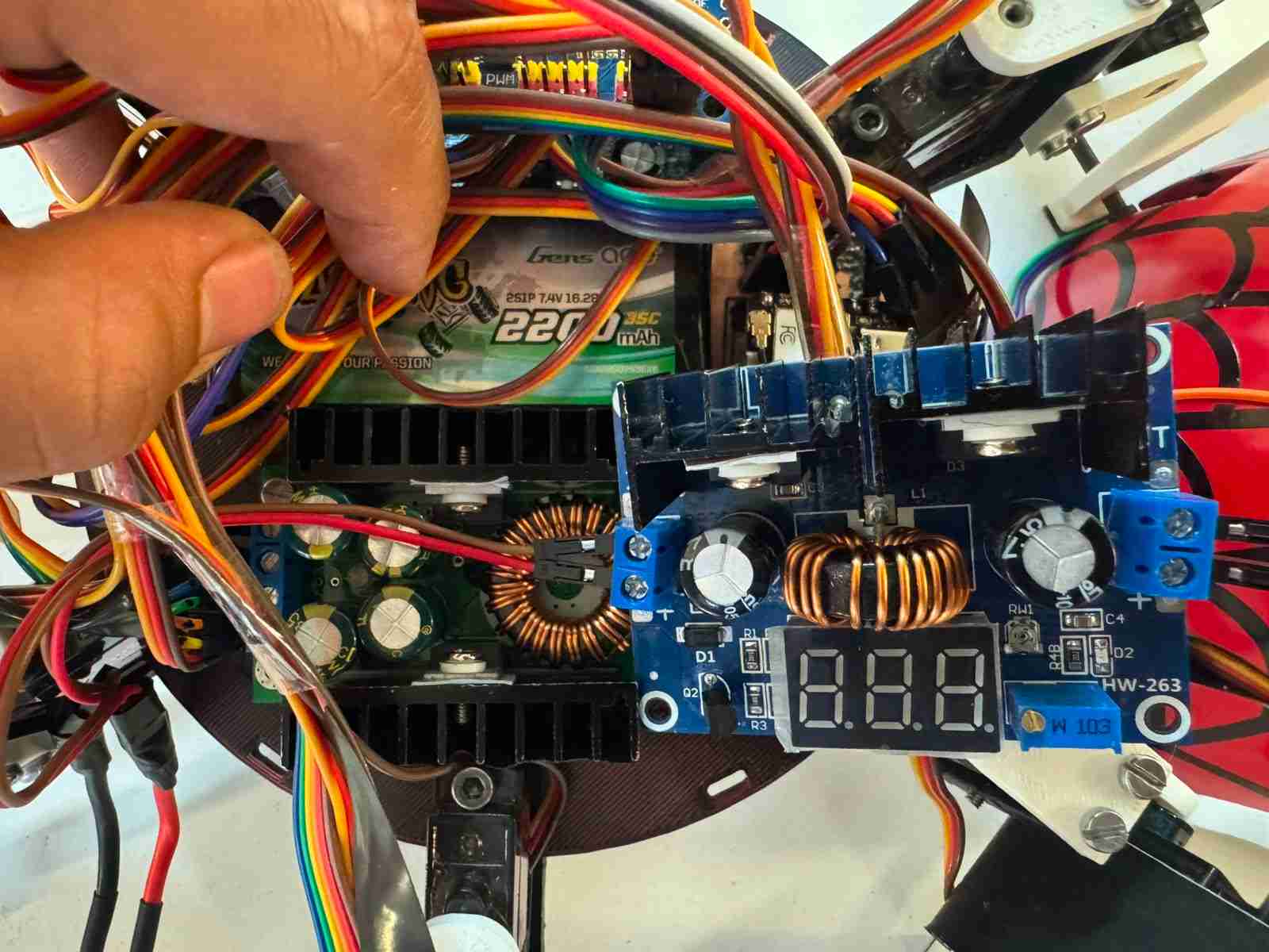
5.1.2 External Satellites and Modular Peripherals
To optimize weight distribution and mechanical adaptability, several critical components are treated as modular external satellites connected to the main PCB via structured wiring harnesses and high-quality pin headers:
- XIAO ESP32-S3 Sense (Camera Module): Mounted externally on a custom front-facing bracket to clear the chassis line-of-sight. It is connected through flexible jumper cables carrying the dedicated 5 logic supply, GND, and data signals, ensuring the RF antenna remains clear of electromagnetic interference (EMI) from the structural servos.
- Dual PCA9685 16-Channel PWM Drivers: Positioned strategically near the coxa joints of the hexapod. These modules offload the processing burden from the main microcontroller by handling the PWM generation for the 18 servomotors via a shared I2C bus connected directly to the main PCB logic interface.
- VL53LXX-V2 Time-of-Flight (ToF) Sensors: Positioned on peripheral arrays for spatial awareness. They utilize their respective XSHUT lines routed from the main board to dynamically assign unique I2C addresses upon system boot, avoiding standard address collisions on the shared bus.
- Passive Buzzer Module: An external acoustic indicator driven by a dedicated digital line (GPIO20) from the XIAO ESP32-C6 to provide real-time state machine diagnostics and battery low-voltage alerts.
5.2 PCB design
5.2.1 PCB Design: Power Integrity and Dual-Capacitor Decoupling Network
Ensuring a stable voltage profile across the PCB requires addressing power integrity at both the macro and micro levels. To achieve this, a Dual-Capacitor Decoupling Network is implemented in parallel at the power input pins of both the XIAO ESP32-C6 and XIAO ESP32-S3 modules. This multi-tier filtering strategy compensates for the non-ideal parasitic characteristics—specifically Equivalent Series Resistance (ESR) and Equivalent Series Inductance (ESL)—inherent to different capacitor technologies.
5.2.2 High-Frequency Noise Mitigation: 0.1µF Ceramic Capacitors
The 0.1µF ceramic capacitors serve as the first line of defense against high-frequency electromagnetic interference (EMI). Microprocessors operating at high clock speeds and RF switching circuits (such as the 2.4 GHz Wi-Fi radio) inject high-frequency ripple into the power planes. Due to their ultra-low ESR and ESL, ceramic capacitors exhibit very low impedance at Megahertz (MHz) scales. This allows them to react within nanosegundos, shunting high-frequency transient noise directly to the GND copper pour before it can corrupt the digital logic states of the microcontrollers.
5.2.3 Transient Bulk Storage: 100µF Electrolytic Capacitors
Conversely, high-frequency filtering is insufficient to prevent localized voltage sag during sudden, macro-level current surges. When the ESP32-S3 initiates high-resolution video streaming, its current consumption spikes instantly by up to 350 mA. Since switching regulators (like the MP1584EN) suffer from a finite loop response delay, this surge causes a localized transient voltage drop.
To resolve this, 100µF polarized electrolytic capacitors are placed immediately upstream of the ceramic filters. These components act as localized chemical energy reservoirs. During an instantaneous load surge, the electrolytic bulk capacitor discharges its stored energy into the power rail within microseconds, buffering the current demand until the main buck regulator can adjust its duty cycle.
Layout Constraint Rule: To maximize the effectiveness of this network, the 0.1µF ceramic capacitor is placed as physically close as possible to the microcontroller power pins to minimize trace inductance, while the 100µF bulk electrolytic capacitor is positioned immediately behind it, creating a structured low-impedance path from the power source.
Is imporatat to note that last but not least I put a led conected to the 5V In to know whne the PCB is powered.
Here is the schematic of the PCB
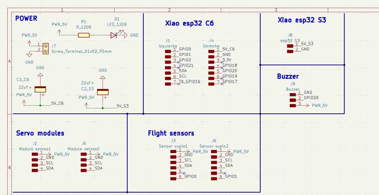
Here is the PCB layout of the final PCB.
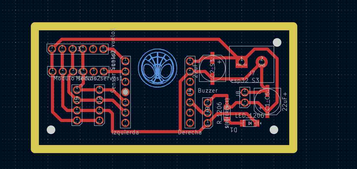
5.3 Electronic production
I made this PCB on the Roland Monofab machine that we have here ai Ibero Puebla.
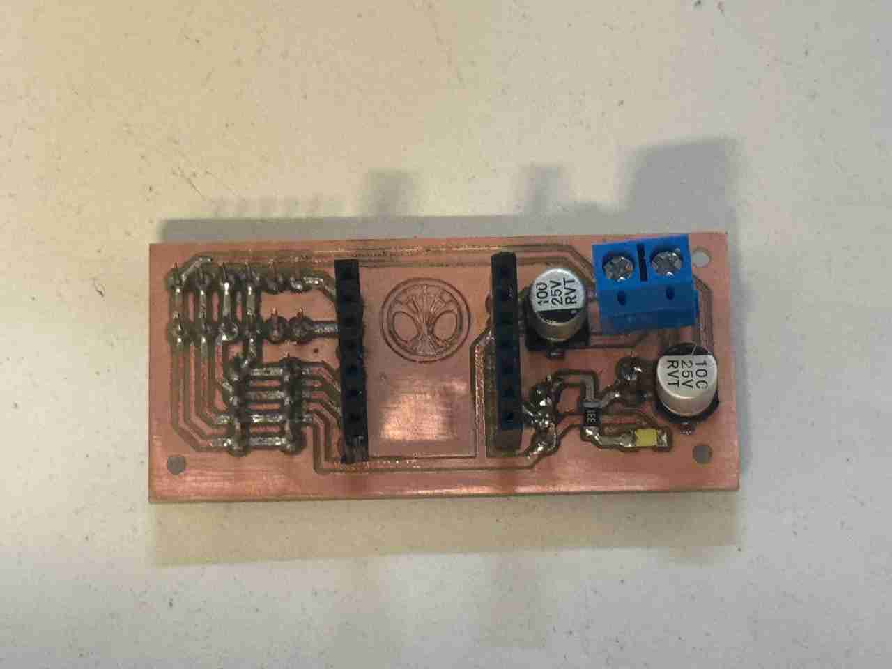
Here is the final result testing the spiderbot with the new PCB.
6. System integration
As I mentioned in week 15, my idea is to make a case that completely covers almost all the cables to give them some organization, even if only superficially, and to give a good finish.
I also noticed that I could directly integrate the camera and buzzer into this housing, which will have press-to-fit joints connecting to the cuerpo V2. I'll take advantage of the fact that my frame's geometry is a circle to perform a revolution operation and generate this dome without too much complication.
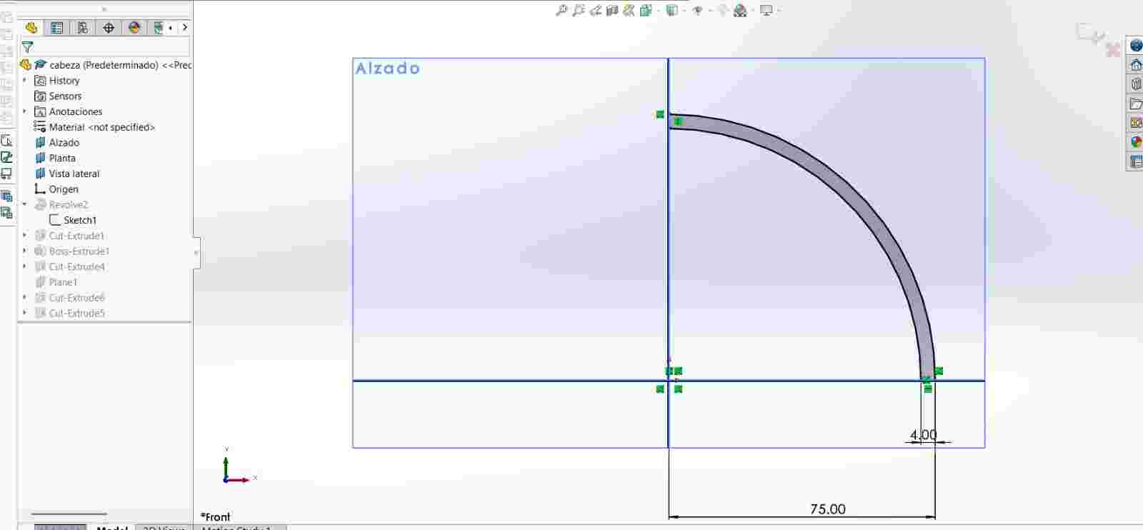
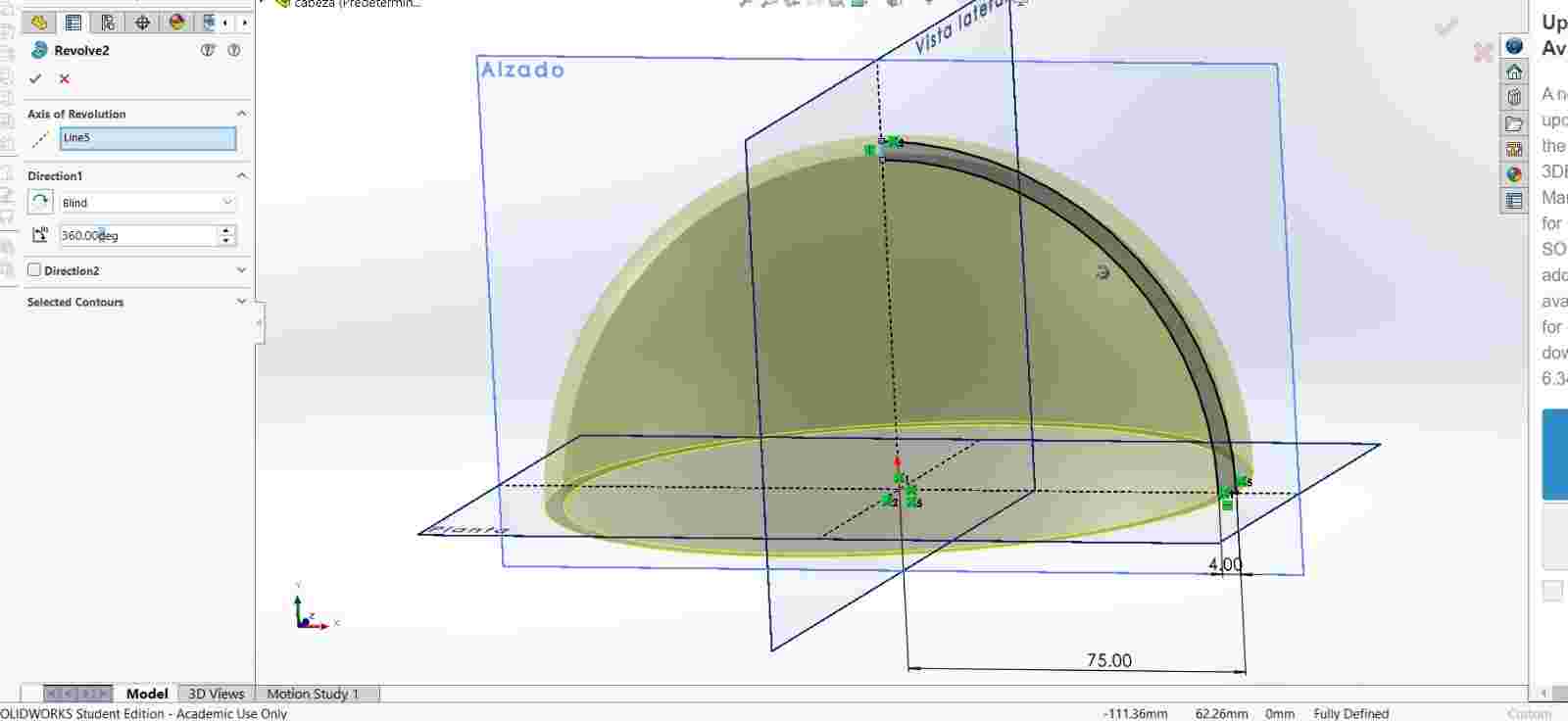
Then cut the holes where the servomotors are located so that it can easily fit in and cover most of the body area.
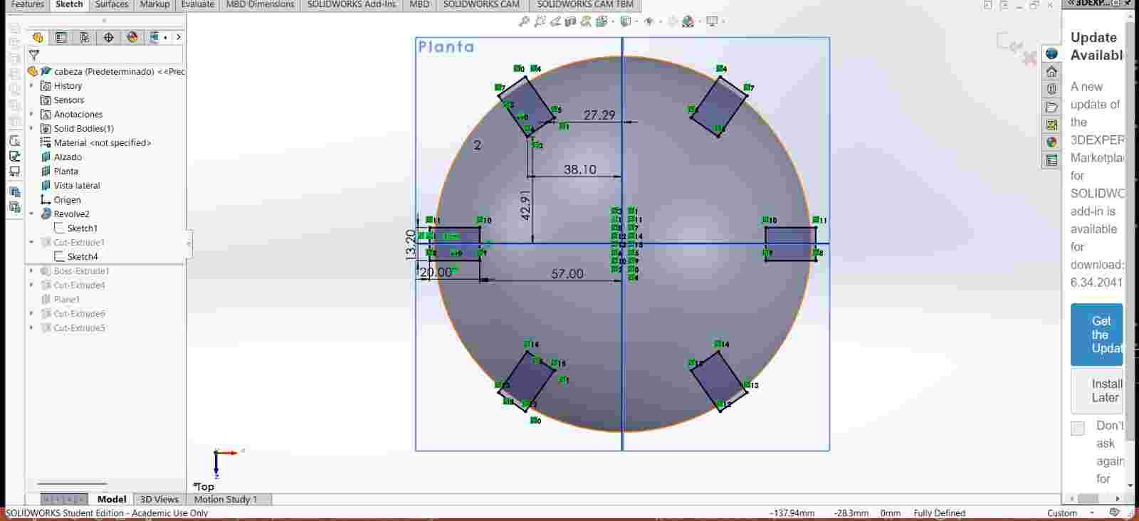
Then I added the tabs for the joints
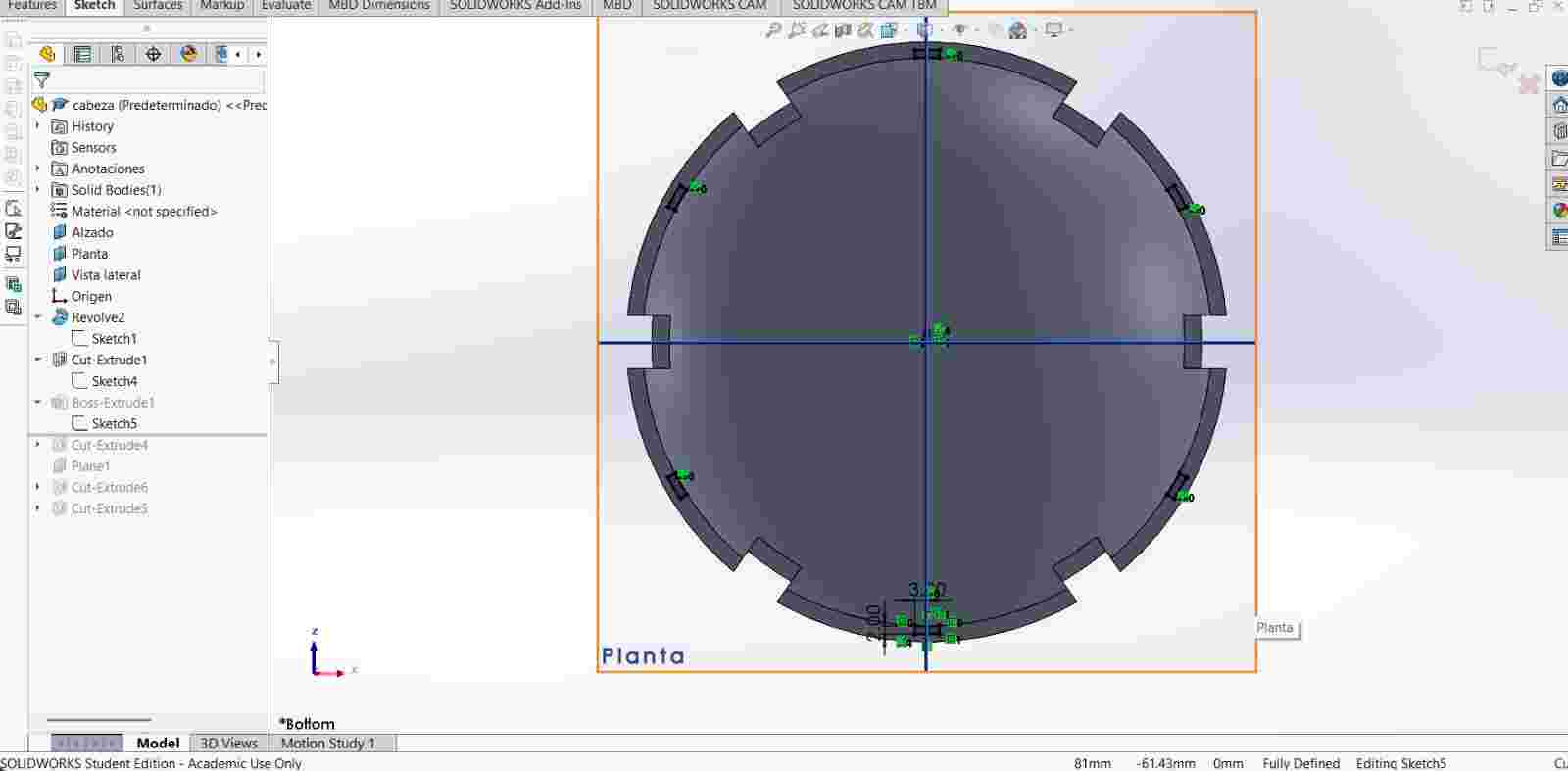
After I created both holes for the buzzer and the camera.
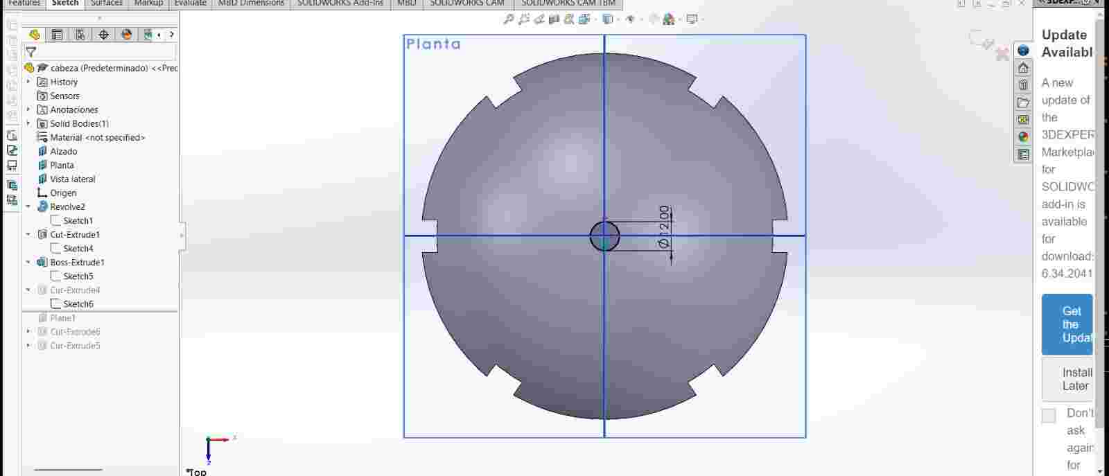
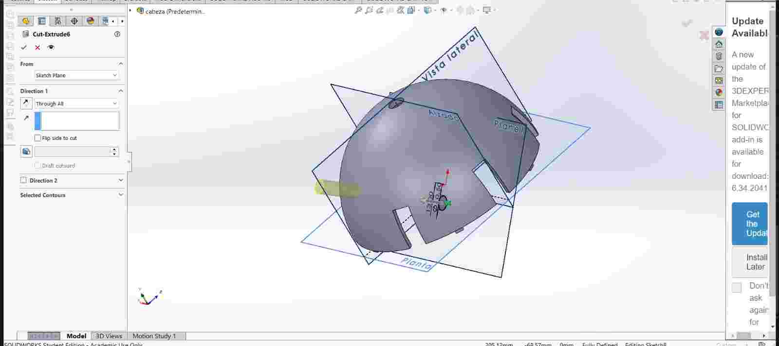
Here is how it looks in the assembly
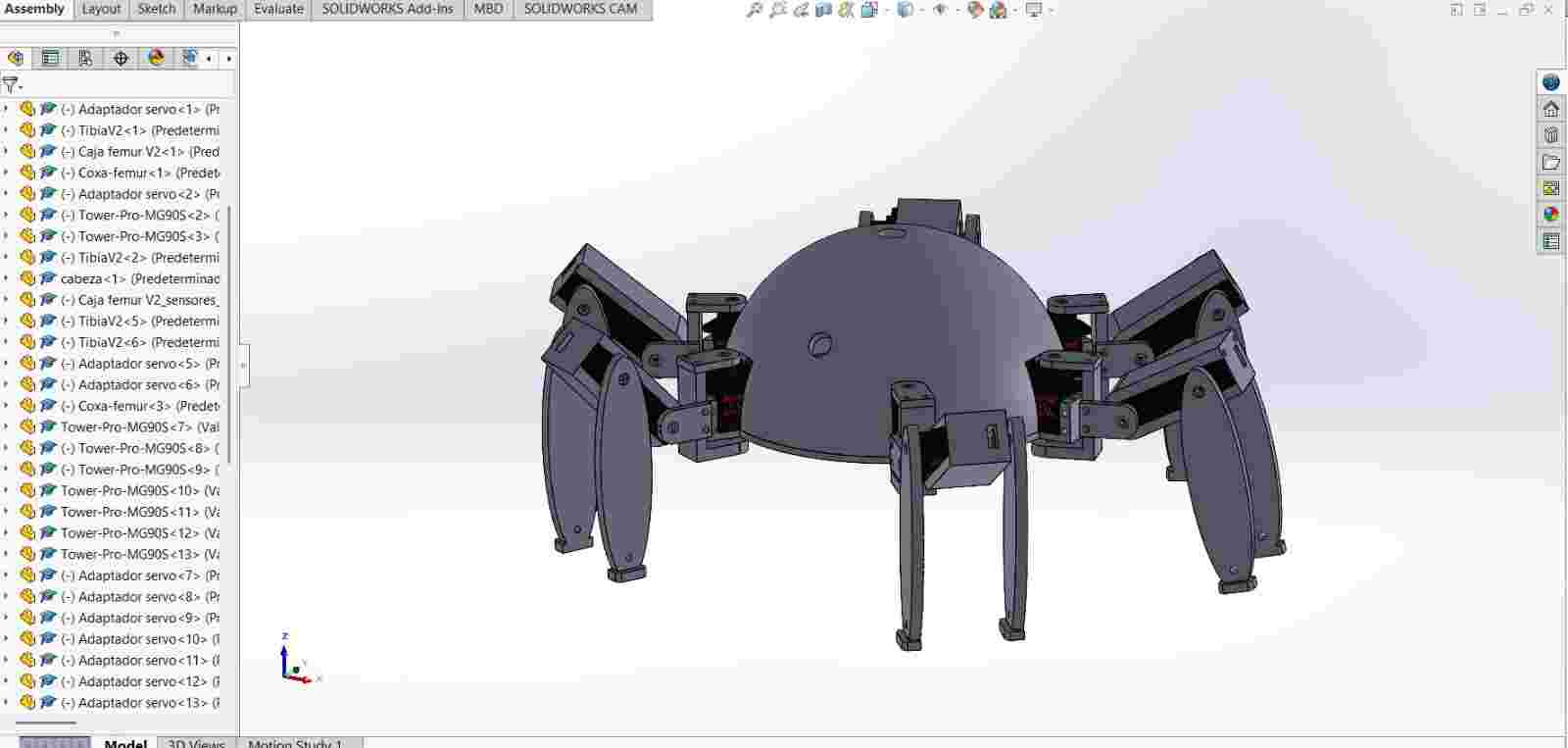
Here is how it looks printed and assmbled on the skeleton
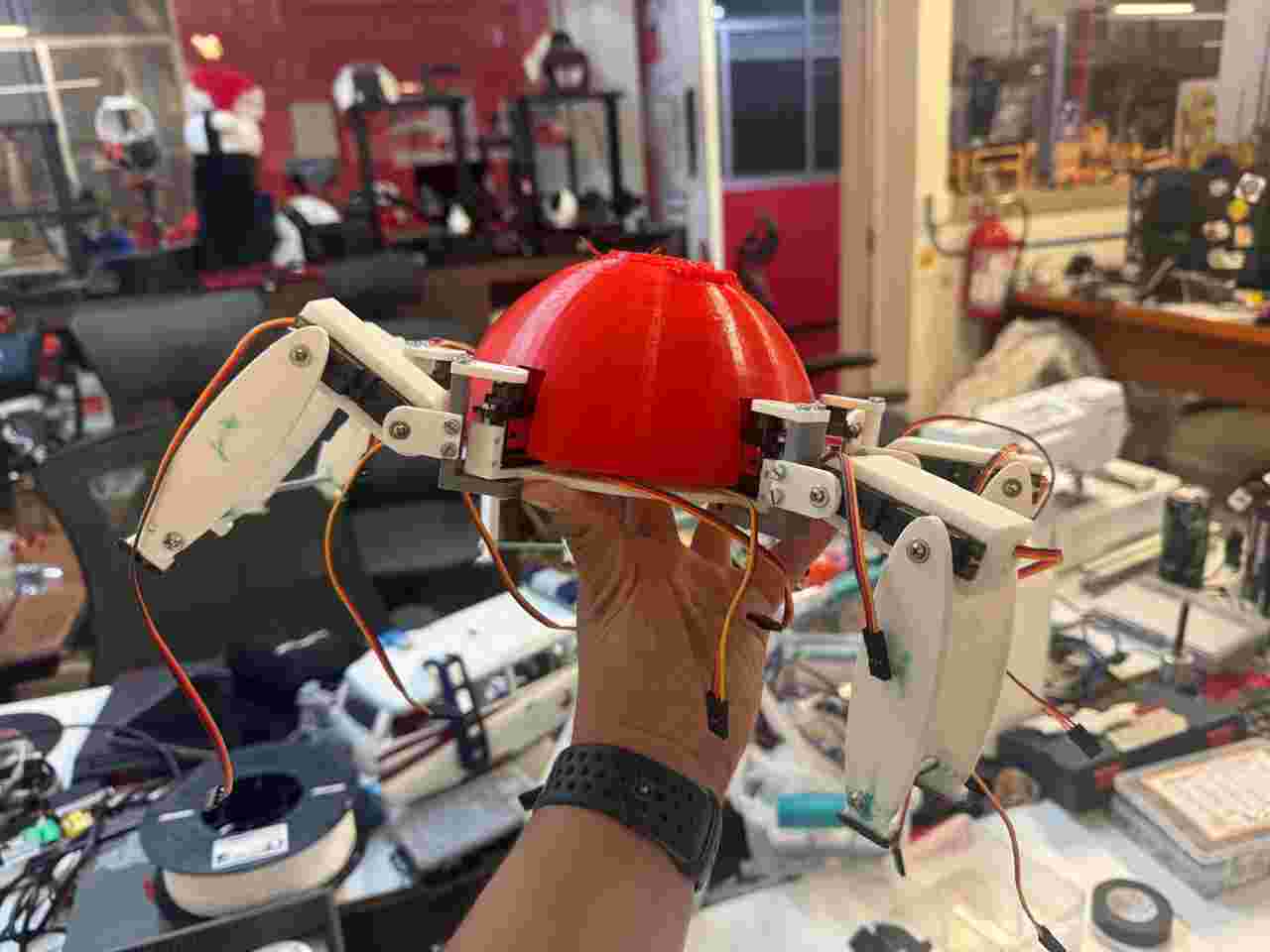
To organize the cables inside the dome, I will group the cables from each leg so I could differentiate which leg was the bundle of cables. I also marked were the screwed components should go like the modules or the PCB to the body so they would be static without affecting the body's center of gravity.
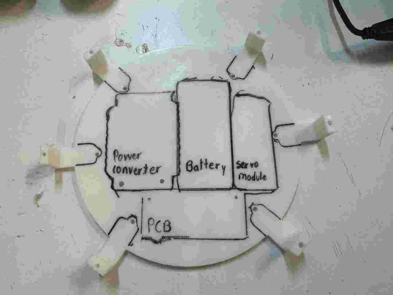
Here is how the final accomodation of the cables and components looks like.
7. 3D printing
As previously seen, I am using 3D printing to manufacture all my parts because this method is fast and allows me to make almost instantaneous corrections.
All the pieces were printed on a Prusa MK4s using the Prusa Slicer
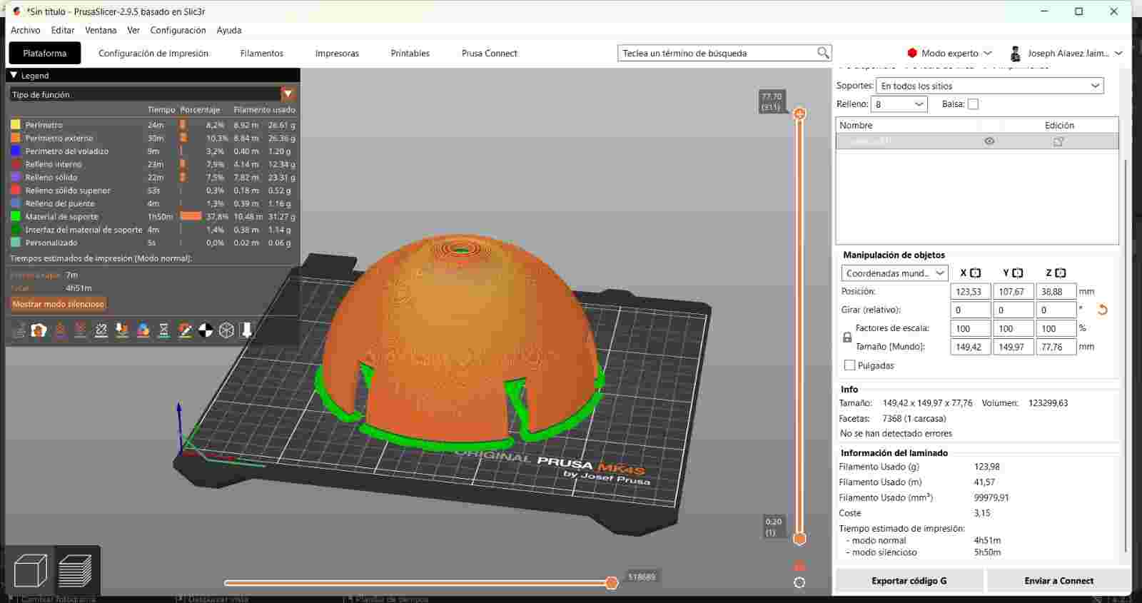
The current number of parts to print in PLA for the final result are:
- 12 Tibia V2
- 4 Caja femur V2
- 1 Caja femur V2 sensor derecho
- 1 Caja femur V2 sensor izquierdo
- 12 Servo adapter
- 6 Coxa-femur
- 1 head
- 1 Body V2
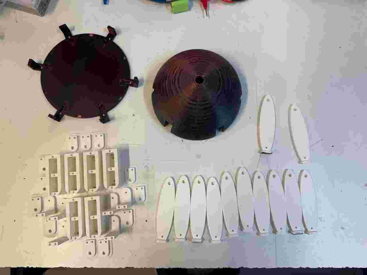
For the post-processing stage I printed TPU eyes that I designed in blender (the pattern I used was also designed by me :)).
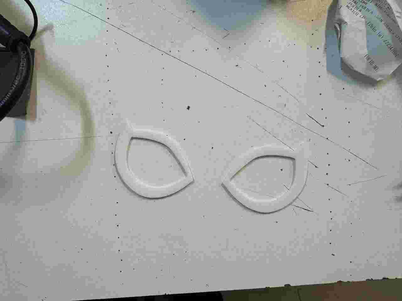
8. Post-processing
Post-processing is divided into sanding, painting (any desired color), vinyl, painting (clear to give shine and protect the colored paint) and handmade items.
8.1 Sanding
To sand, we start with the lowest grit number and work our way up to the highest. In my case, I first sanded with 120 grit sandpaper, then wet it to remove excess dust, and sanded again. When the surface feels somewhat smooth, we can change to a different grit sandpaper, in my case 400 grit, and repeat this process until we obtain a smooth and even surface.
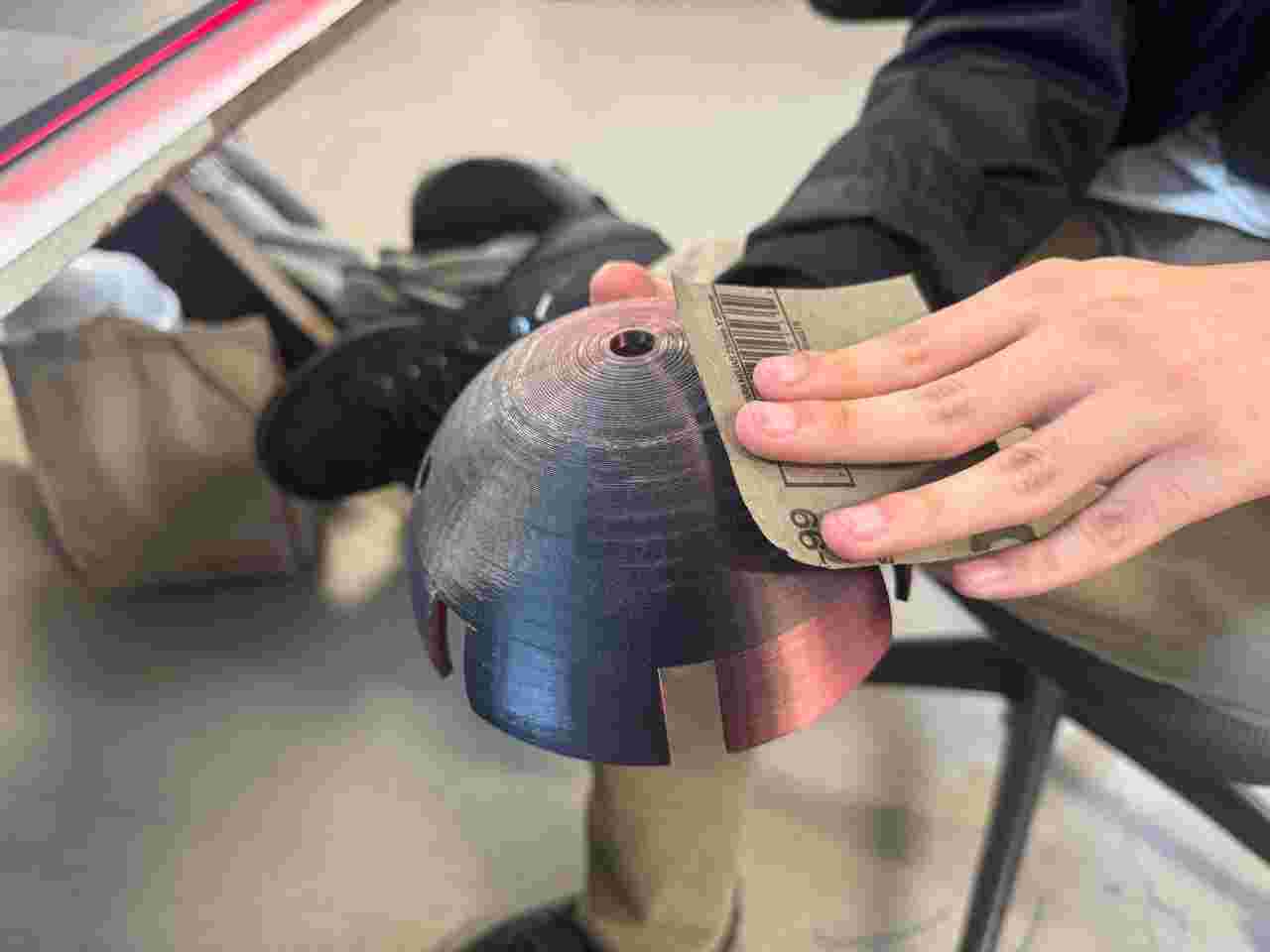
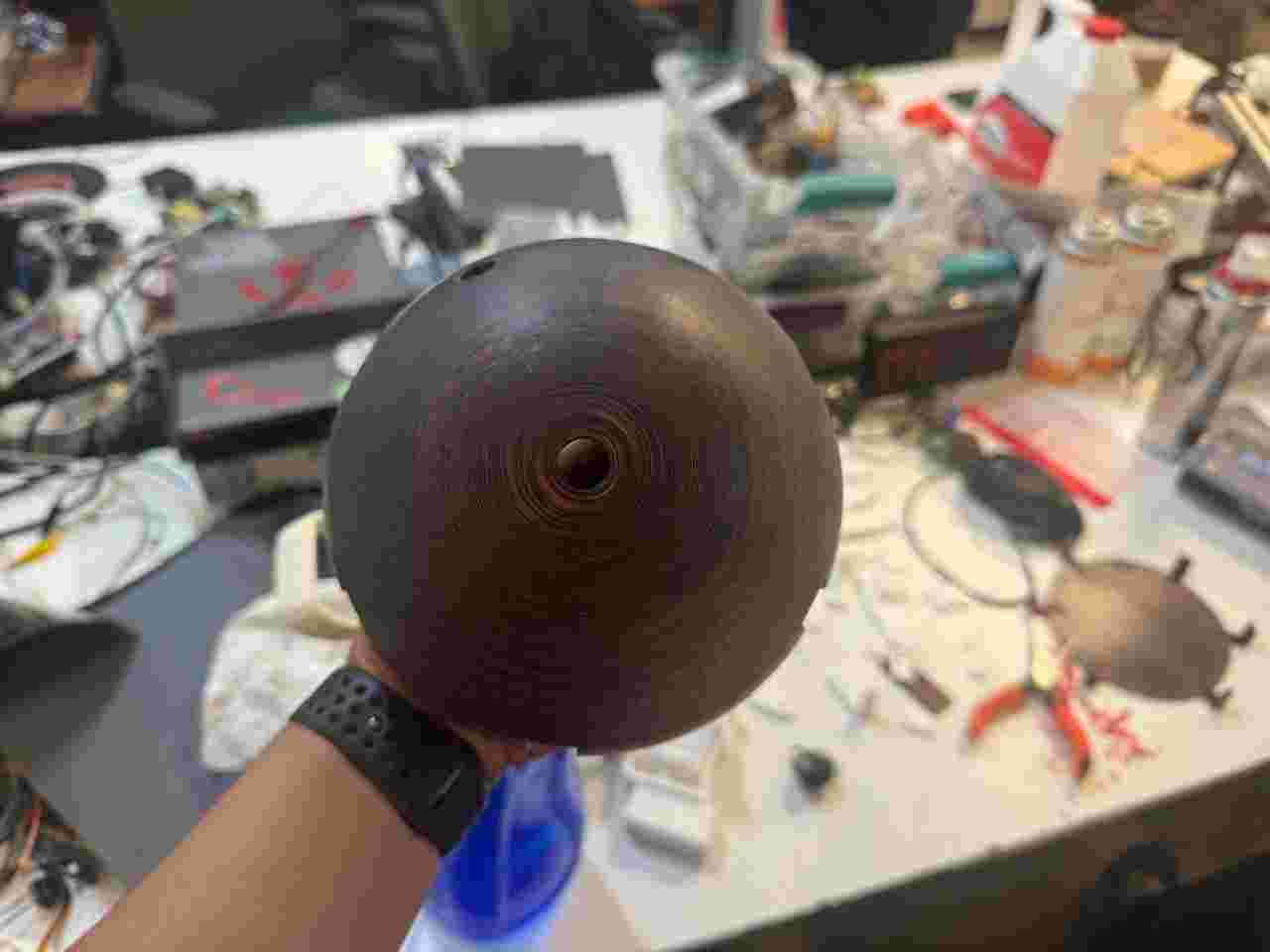
8.2 Painting
I painted almost all the pieces black, except for the body and head. The head was first primed white and then painted red.
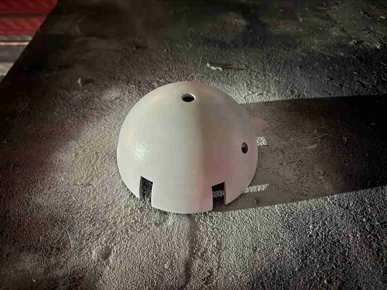
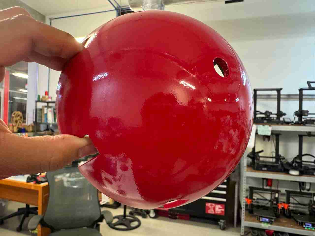
Here is how all the pieces look
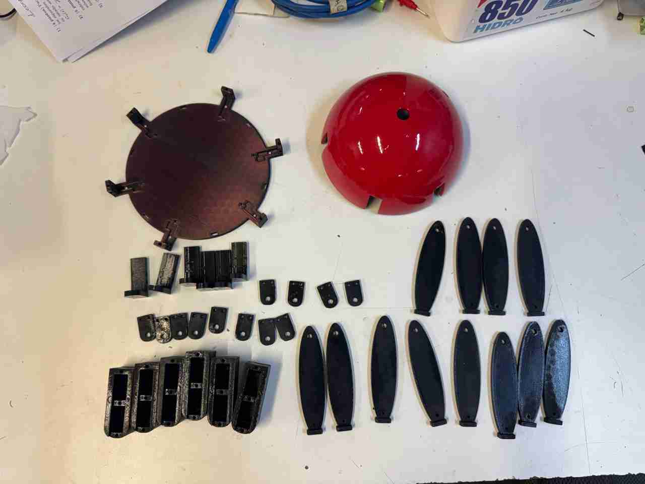
One comment I'd like to make is that for the final body assembly I'll be using the servo adapter and Tibia v2 parts unpainted, since during testing the paint increased or modified the joint holes, causing it to move and fall off.
8.3 Vynil and painting
I'll use the spiderweb sticker I made during week 3, but now on a larger scale, as that will be the spiderweb pattern for my Spiderbot. I just have to get it cut and adjusted to the correct size.
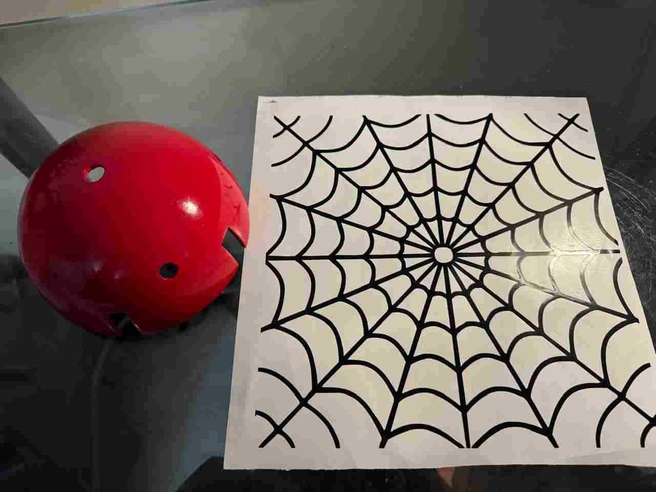
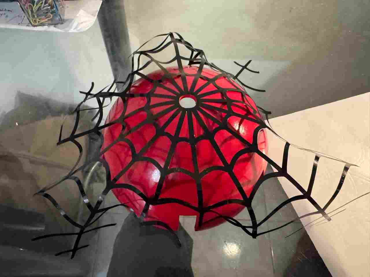
Because it's a curved surface, some spiderwebs won't fit; you'll have to cut them by hand and adjust them.
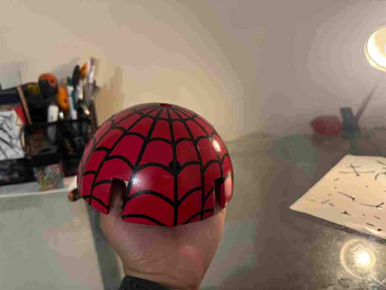
After applying the vinyl, I will apply three coats of clear spray paint to achieve a glossy finish and protect the base paint.
8.4 Handmade items
These were two objects, the lenses, which are purely decorative. They were made with micro-perforated vinyl and plastic bottles to achieve that curved effect. Is also important to mention that I painted the lenses color black.
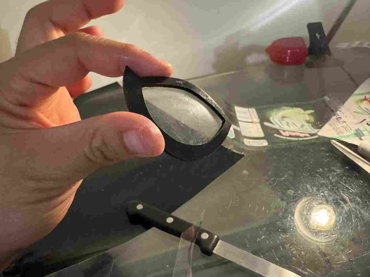
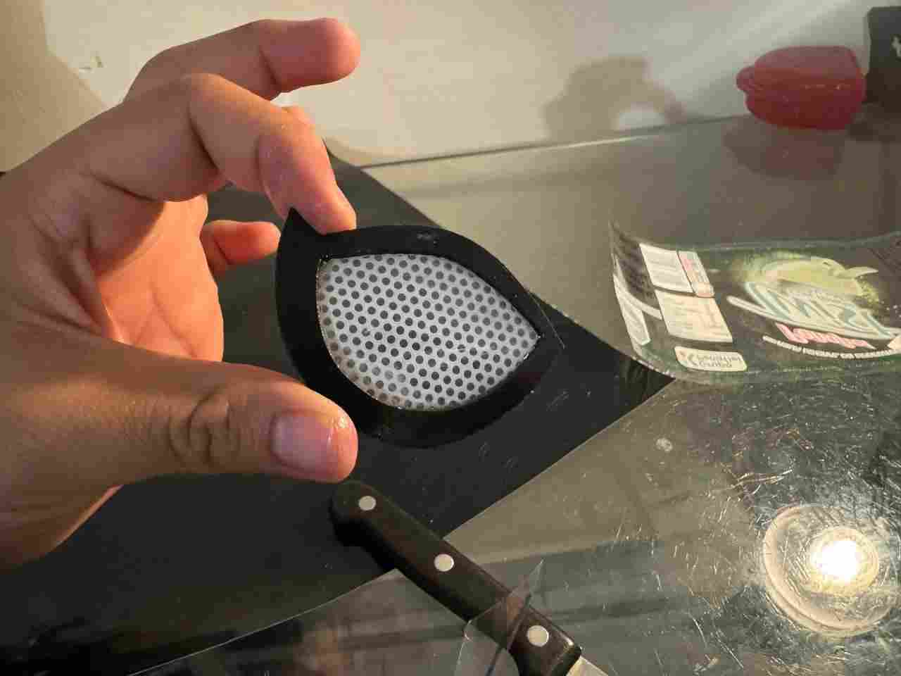
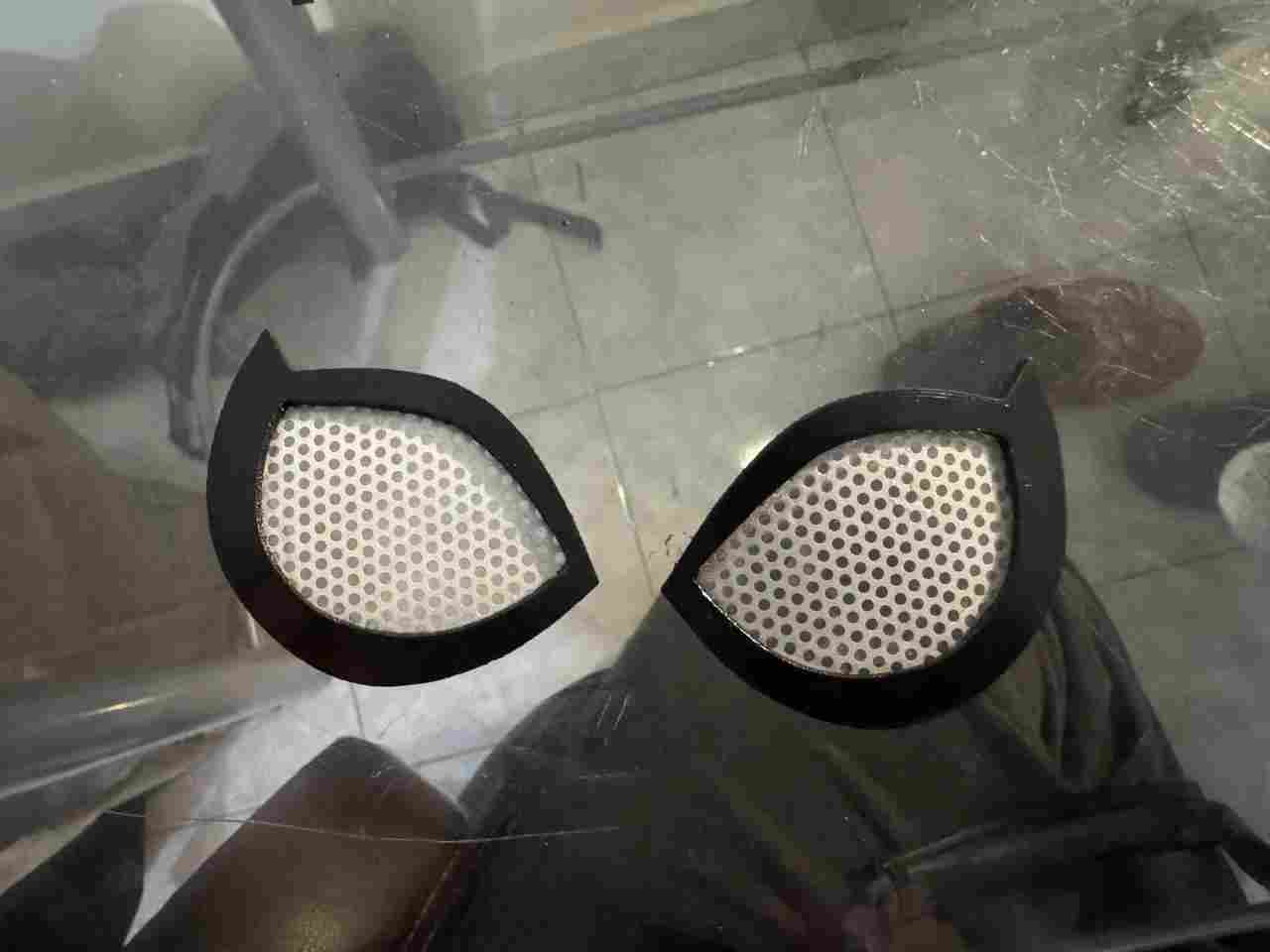
Finally, all that remains is to glue them to the dome.
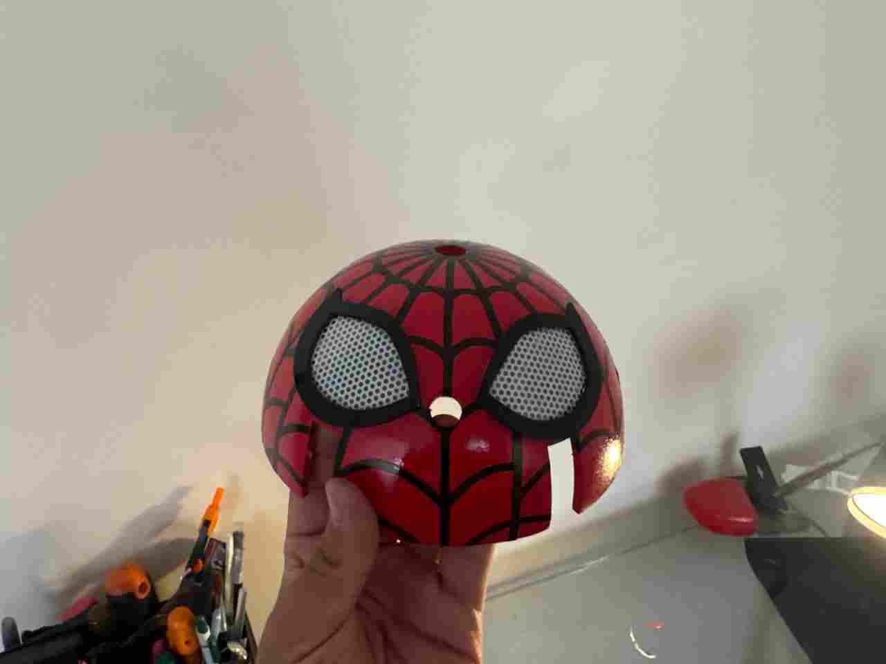
9. Final result
Once we have all the pieces finished and ready to assembly (remember that tibia V2 and servo adapter must no be painted) we will have to repeat the same process for assembly and calibrating the servomotors as we did on body design.
The components on top of the body (electronics) can be in any order; it doesn't really matter since none of them interfere with each other. It should look somethinglike this
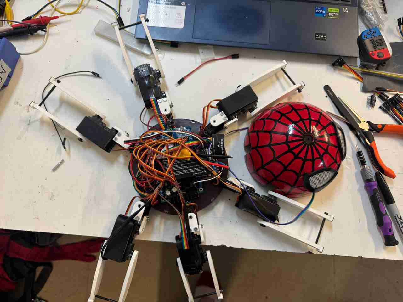
Finally, after integrating all the previous processes, the final result of the spiderbot looks like this.
10. Files created
Click here to create your own Spiderbot, thanks for being with me during all my way.
I wanna thanks to my parents and my friends for always support me, cheer me up when I didn't feel like working and for believe in me. I love you :D