Week 15. Systema integration
Summary
This week I focused to the organization and planning of the integration of my final project which I like to call "spiderbot" but in fact is an hexapod that the user will be able to controll it via Wifi and their mobile phone. I devided the final project into 4 sections: electronics, mechanical, programming and final design
1. Electronics
For this section I subdevided it into:
- Microcontrollers
- Inputs and outputs (What components will I use?)
- Powering (What type of battery will I use)
- PCB (What will it do?)
1.1 Microcontrollers
I will use 2 microcontrollers a Xiao esp32 C6 and a Xiao esp32 sense S3.
1.1.1 Xiao esp32 C6
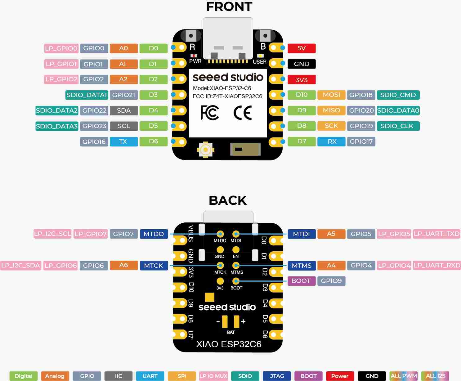
This microcontroller will handle the control aspect, sending information to the phone and receiving signals from the user when they touch the phone's screen. I'll use this microcontroller because it has Wi-Fi, which is necessary in my case so the user can control the Spiderbot from a medium distance and receive an immediate response. Also, as I don't need to use many pins, so I didn't consider using the base ESP32 necessary.
1.1.2 Xiao esp32 sense S3
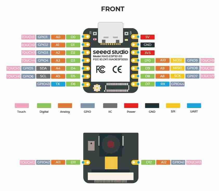
The sole function of this microcontroller is video transmission, allowing the user to see what the spiderbot sees from the front, since the idea is for the user to remain stationary while the spiderbot moves freely. Furthermore, during testing, I noticed that the video transmission causes the microcontroller to overheat significantly, so in my opinion, using it for anything else could cause it to burn out.
1.2 Inputs and outputs
For this part I will use:
- Servomotors (completely in charge of the movement)
- Servomotor module (Beacuse of the number of servomotors that I will use, I ran out of pins if I don´t use this modules).
- Flight sensors (in charge of detecting the distance between the middle leg of each side and any object, in order to not crash)
- Pasive buzzer (this one is purely decorative because I wnat the spiderbot to make noise if you tap on certain button on the interface)
- Xiao esp32 sense S3 (video transmission)
1.3 Powering
The proper functioning of the spiderbot with an estimated weight of 1.5 kg and 18 MG90S servomotors requires a robust, efficient, and protected power supply system. The main challenge in this type of mobile robotic system is electromagnetic noise and the drastic voltage drops generated by the motors under load (voltage sag), which can cause unpredictable restarts in the control and processing stages located in the XIAO ESP32-S3 and C6 modules.
To solve this problem, I will implement a split power supply architecture Dual-Bus, completely isolating the power stage electromechanical force from the logic stage processing and sensors. I will also include electrical protection through fuse
1.3.1 Primary Power Source: Gens Ace 2S 7.4V 2200mAh 35C LiPo Battery
The choice of the Gens Ace Bashing 2S battery (7.4V nominal / 8.4V maximum charge) with a capacity of 2200 mAh and a constant discharge rate of 35C is justified by the analysis of the worst dynamic scenario.
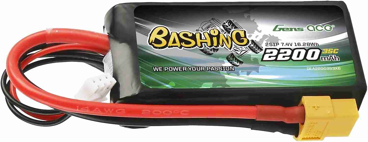
To determine the viability and safety of the primary power source, the maximum sustained current that the Gens Ace LiPo 2S (7.4V) battery can continuously deliver was calculated based on its nominal capacity and discharge rate specifications. Converting the 2200 mAh capacity to its equivalent in Ampere-hours (2.2 Ah) and multiplying it by its physical performance factor of 35C, the standard electrical discharge equation Maximum Current = Capacity times Rate C is applied, yielding a theoretical safe delivery capacity of up to 77 Amps. By comparing this physical limit with the critical maximum demand calculated for the 18 MG90S servomotors of the hexapod (13.5 A in stall condition), it is validated that the battery will operate with a safety margin greater than 500%, guaranteeing a highly stable, cool and free power delivery without severe voltage drops during dynamic walking routines.
Although under standard continuous operation, the duty cycle is estimated to have an average nominal current draw between 4.5 A and 5.5 A.
With this, we can calculate the usage time by dividing 2.2 Ah by 5 A, which gives us approximately 26 minutes of usage time.
1.3.2 Electromechanical force power stage
The 18 MG90S servomotors operate at their optimal torque curve at 6.0V. Because the average system current is 5 A with peaks of 13.5 A, the XL4016 integrated circuit will be used to power the module.
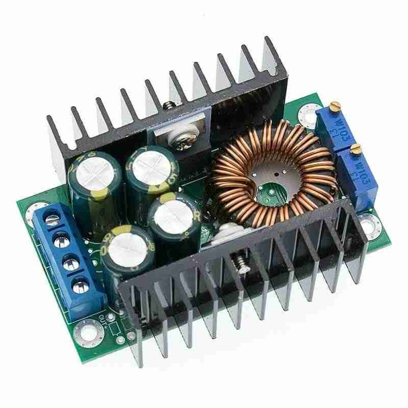
This robust, high-efficiency power module is designed to handle continuous nominal currents of 9 A (with built-in passive dissipation) and peak currents of up to 20 A with forced cooling. It more than covers the spiderbot's power demands, ensuring highly efficient thermal energy conversion from the battery's 7.4 V to the stable 6.0 V required by the servo distribution lines on the PCB.
1.3.3 Processing and sensors stage
The Seeed Studio XIAO family of controllers (ESP32 sense S3 and C6), along with the VL53L1X time-of-flight (ToF) range sensors, require a fixed, extremely clean, and noise-free 5.0V power supply.
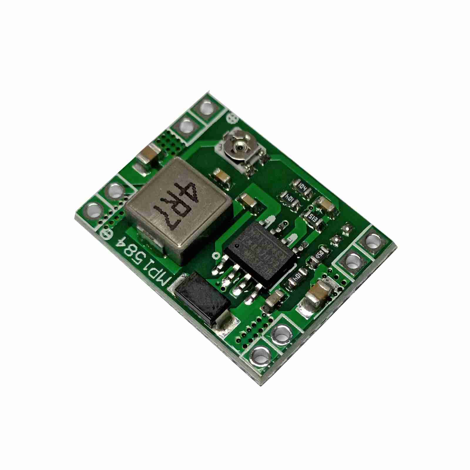
The MP1584EN module was selected for its ultra-compact size (ideal for optimizing physical space on an integrated PCB) and its excellent high-frequency switching performance, capable of delivering up to 3A. By exclusively powering the system logic (whose combined current draw does not exceed 500mA), this module operates with absolute safety margin and remains completely immune to any disturbances or voltage drops that the servos on the XL4016 line might experience.
1.3.4 Electrical Protection: PCB Mounting Safety Fuses
Since lithium polymer (LiPo) batteries with high discharge rates (like this 35C one capable of delivering 77 Amps instantaneously) are dangerous power sources in the event of mechanical short circuits or welding failures, it becomes strictly mandatory to include a redundant active protection system:
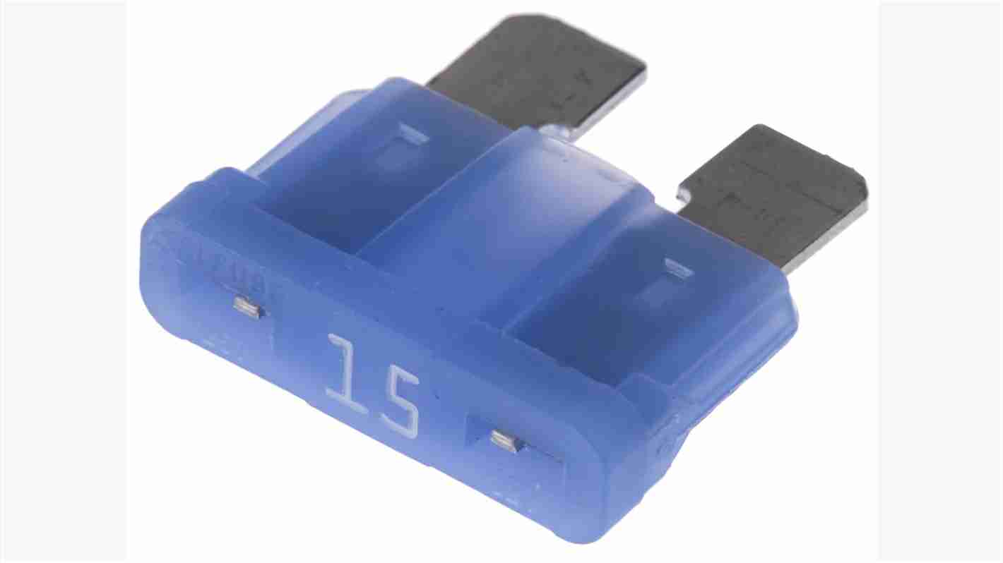
- Inclusion of Mini/Micro Blade Type Fuse Holder on PCB: The motherboard will be designed to include a black automotive fuse holder socket soldered directly in series with the main positive line of the battery (just after the XT60 connector).
- Fuse Sizing (15A): A 15A automotive fuse has been selected for the main line. By placing it above the robot's worst-case dynamic current draw (13.5 A), false trips due to thermal fatigue are avoided during normal operation, but immediate filament breakage is guaranteed if the current spikes to the 77A short-circuit current.
- Maintainability: The use of the plastic fuse holder ensures electrical isolation from the board's ground plane and allows for "snap-on" cartridge replacement in seconds, protecting the PCB's copper traces, regulators, and most importantly, the battery's physical integrity against catastrophic failures or fires.
1.4 PCB
For the hexapod's electronic system, a single integrated main PCB (motherboard) design was chosen. Centralizing everything on a single board minimizes the use of external wiring, reduces electromagnetic noise, and decreases critical points of failure due to poor connections. As the PCB is not designed yet I will explain the PCB layout and connection flow that are structured as follows:
- Power Input: The Gens Ace LiPo 2S battery connects directly to the PCB via an integrated XT60 male surface-mount connector. The main positive line passes directly through the 15A protective fuse holder soldered to the board.
- Regulation Channel Division: After the fuse, the battery voltage branches in parallel to the inputs of the two switching regulators: the massive XL4016 converter (power stage) and the reverse protection diode SS34 preceding the MP1584EN mini module (logic stage).
- Power Line (6.0V): The XL4016's regulated 6.0V output directly powers the high-current traces (minimum 3.5 mm wide) for the terminal blocks and power pins of the 18 MG90S servomotors. A 2200 µF electrolytic capacitor is connected in parallel to this bus to filter mechanical demand spikes.
- Logic and Control Line (5.0V): The stable 5.0V output of the MP1584EN powers the power rails of the female header strips where the XIAO ESP32-S3 and XIAO ESP32-C6 microcontrollers are mounted, ensuring a clean processing environment. Similarly, the power connections for the VL53L1X ToF distance sensors and the PCA9685 I2C servo control module are derived from this 5.0V bus.
2. Mechanical part
For this section I subdevided it into:
- Design of the pieces (basic shapes)
- 3d prints
- Digital and physical assembly
- limitations and corrections
2.1 Design of the pieces (basic shapes)
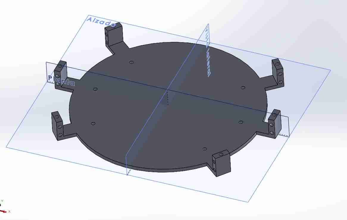
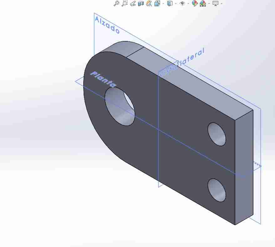
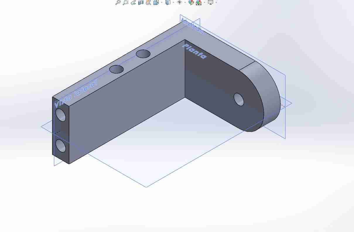
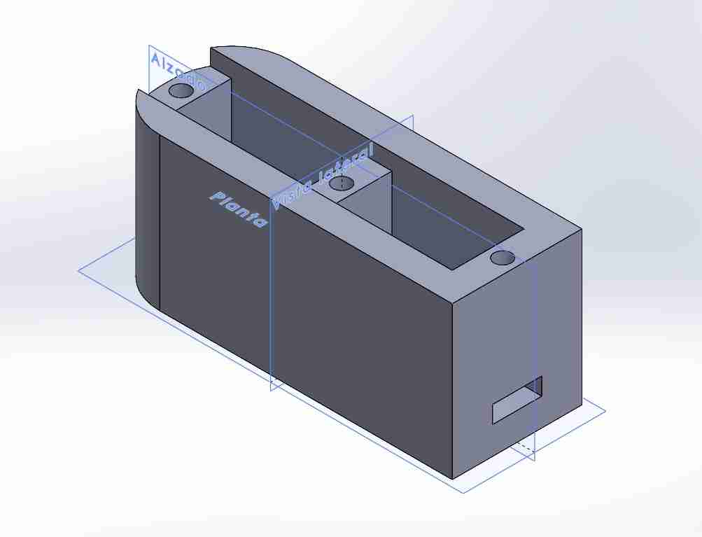
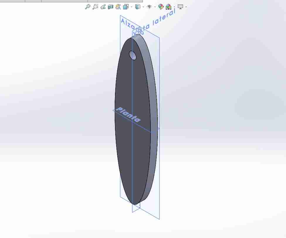
For doing 1st test and making corrections od the body and other parts I designed all the parts in a simple way so I can 3D printed them faster and make corrections quickly, the idea is to keep this desgin so the final design will just be a cover for this and the electronics that can be removed easily.
Here are body, coxa, femur, tibia and ither parte that are necessary for the assembly so I can use press to fit joints for the servomotors.
2.2 3D printing
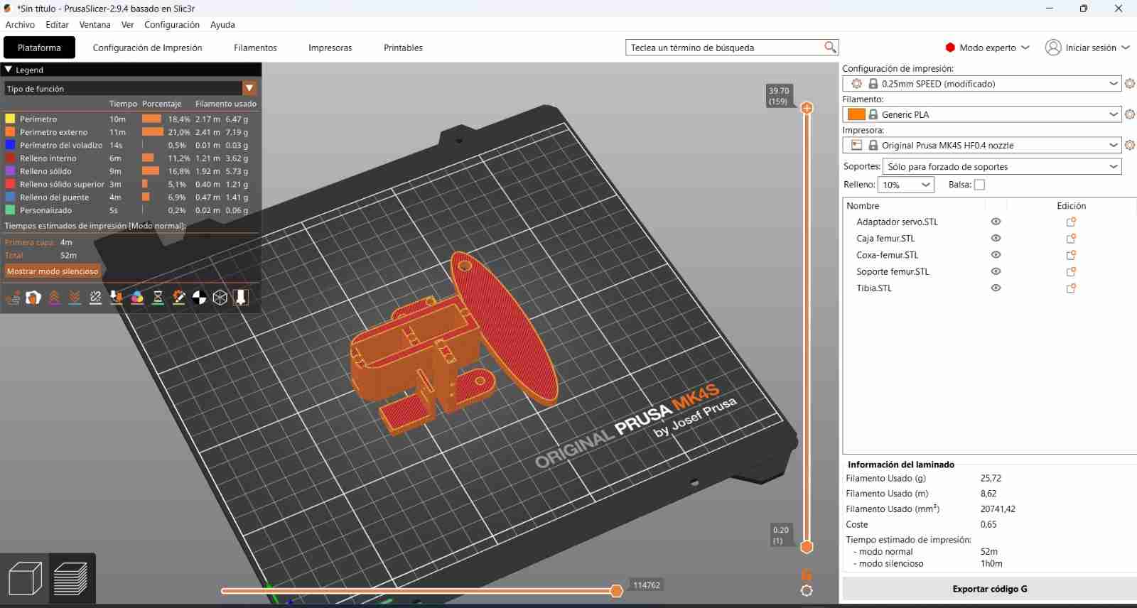
As I already said I will 3D print all the parts in a Prusa MK4S.
Here is the view on the Pursa slicer.
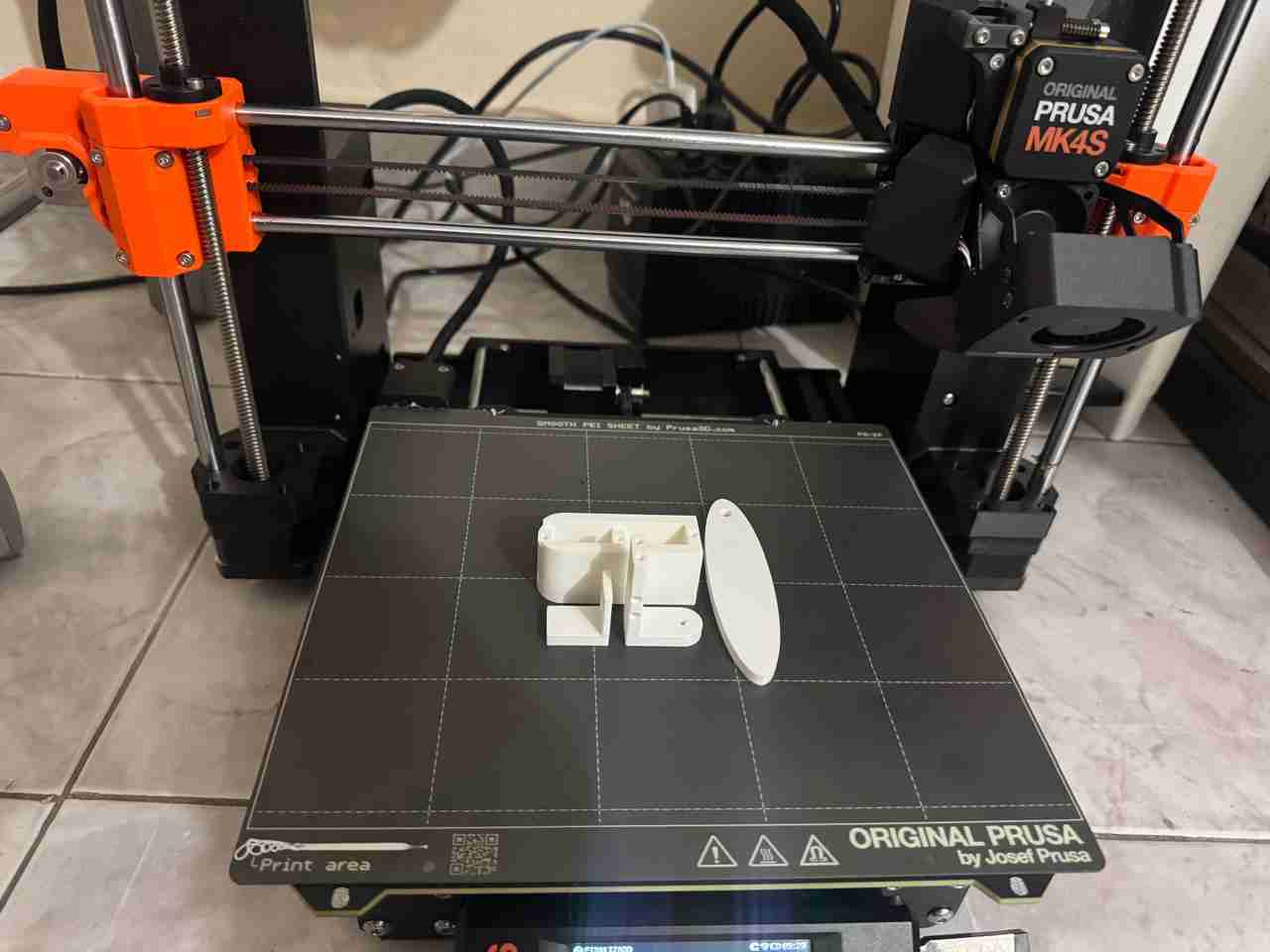
Here are the parts already pirnted.
2.3 Assmbly (digital and physical)
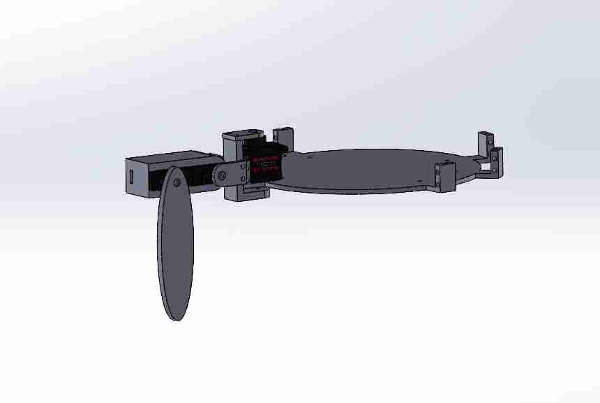
Here is a look of the assembly of one leg in solidworks.
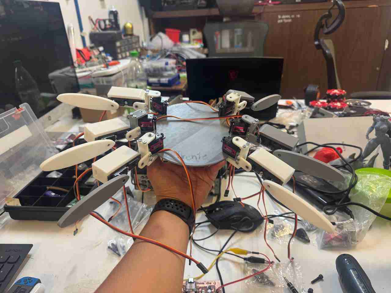
Here is a look of all the legs and the body assembled.
2.4 Limitations and corrections
While doing tests with the PCB that I made during week 11 and using the servomotos modules I noticed that the servos from the coxa have limited motion because they are too close together, for the second version of the body I will modify this part so that all the servos can have a full range of motion; the other parts can move with complete freedom and ease.
3. Programming part
For this section I subdevided it into:
- Control (Node a or code 1)
- Camera (Node b or code 2)
Both of this codes are already explained of how I made them on the week 14 page, This parte is the same that I already did. So I will resume how both codes works.
It is important to mention that both codes connect the microcontrollers to the user's hotspot, since I will use wifi for the communcation.
3.1 Control (Node a or code 1)
The first code runs on the Xia ESP32 C6. Upon connecting to the hotspot, it launches a webpage that the user must add to their phone's home screen to use it as an application. Once this application is open, the phone must be held horizontally. Clicking the green button initiates communication between the phone and both microcontrollers, as the ESP32 C6 is responsible for moving the servomotors, generating noise, and sending information from the flight sensors to determine if the Spiderbot is close to a collision.
3.2 Camera (Node b or code 2)
The second code connects the Xiao esp32 sense S3 to the hotspot and the control or node a so that it can send the video stream on the phone.
Here is the result of how this looks from the phone (screen recording).
4. Final design
The idea for the final design is that the basic shapes have a narrow edge through which to press the final design casing; this casing will house both the electronic components and provide the aesthetic and functional design I am looking for for this spiderbot.
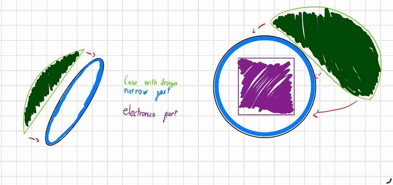
I will of course make a postprocessing of all the pieces in order to make them look like if the spiderbot was the same from the videogame or from Disney. So a lot of sanding and paint is waiting for me.
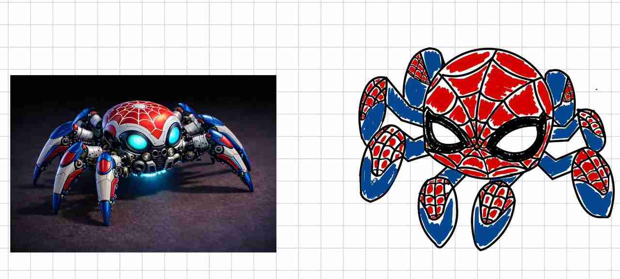
At the end I expect to have something like this sketch that I made or like the image that I generated from gemini (excepth for the metallic part like the gears, because I don' like how that looks). I will try to keep the classic red and blue design.