Week 9. Input devices
Summary
This week we focused on learning how to use input devices, how to use them, recieve responses, activate them and the ways to recieve signals. My device will be a flight sensor Vl53lXX-V2 with a modified board from week 08.
Group assignment
Here is the group assignment to check more information about the topic embedded programming.
1. Input devices
1.1 What are input devices?
Input devices are components that allow a system to receive information from the environment or the user. In electronics and mechatronics, we typically refer to sensors, which convert physical quantities into electrical signals that a microcontroller or computer can process. Essentially, they capture what's happening outside and translate it into data.
1.2 Types of measurements that sensors can perform
- Temperature: Sensors such as thermistors or LM35.
- Light: Photoresistors (LDRs), photodiodes.
- Distance/proximity: Ultrasonic, infrared.
- Pressure: Barometric or force sensors.
- Motion/acceleration: Accelerometers, gyroscopes.
- Sound: Microphones.
- Humidity: Sensors such as DHT11/DHT22.
- Position/rotation: Potentiometers, encoders.
- Magnetic field: Hall effect sensors.
1.2.1 ToF sensors, Time of Flight
Designed to measure distances with high precision, these sensors emit a pulse of infrared laser light and measure the time it takes to bounce off an object and return to the sensor. From this time, they calculate the distance.
- Use direct distance measurement (not estimated by intensity like simple IR sensors).
- Offer high precision (millimeters at short ranges).
- Less dependent on the object's color or texture.
- Use I2C communication.
1.3 What is I2C communication
I2C (Inter-Integrated Circuit) communication is a protocol that allows multiple electronic devices to communicate with each other using only two wires.
1.3.1 How it works
- SDA (data): Where information travels.
- SCL (clock): Sets the pace of the communication.
In example there is a master device (microcontroller) that controls everything, and several slaves (sensors).
1.4 What are libraries?
Libraries are sets of pre-written code that you can reuse to perform specific tasks without having to program them from scratch. they are useful because they save time (don't have to programm from scrath), simplify the code, reduce errors and make working with hardware easier because most sensors have already their own library
1.4.1 What they do?
They include ready-to-use functions, classes and tools like:
- Reading a sensor.
- Controlling a display.
- Handling communication.
1.5 What will I do?
For this week I will use 2 ToF sensors VL53LXX-V2since the idea is to detect how close is the spiderbot's body to any object; the sensors will be attached to the legs, one per side.
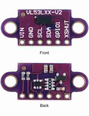
2. VL53LXX-V2 sensor
As I mentioned, the VL53LXX-V2 sensors are designed for highly accurate distance measurement. This particular one is among the smallest in the world, which is why I'll be using it. Since I want it to be as aesthetically pleasing as possible, this sensor size helps achieve that goal.
2.1 Datasheet
At the moment there is no existence for the datasheet of this same sensor but we can use the datahseet from the previous version the VL53L0X that can be found here. We can read the datasheet to know how to activate the sensor or we can also use libraries that simplifies the code on just a few lines.
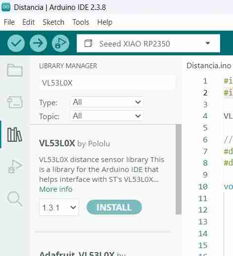
2.2 Libaries
To use this sensor we will install the library VL53L0X by Pololu because it comes with simple functions for initializing and reading distance, without having to configure complicated sensor registers, and instead of writing many lines for I2C communication and calculations.
2.2.1 Install any library
To install any library we will search it in the libraries tab in the Arduino IDE we click on the icon where are many books and search it, then click on install and it will be automatically downloaded.
To learn what functions a library has, click on "More info". This will take you directly to the creator's page where you can read what each function does, how to call it, and the expected result.
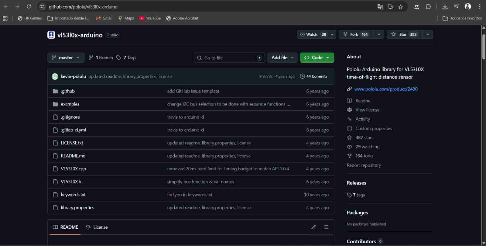
In my case, the file "VL53L0X" is the one that lists the functions and their respective uses. Once you've read it, you can start programming.
2.3 Communication and connections
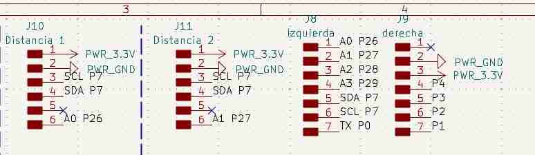
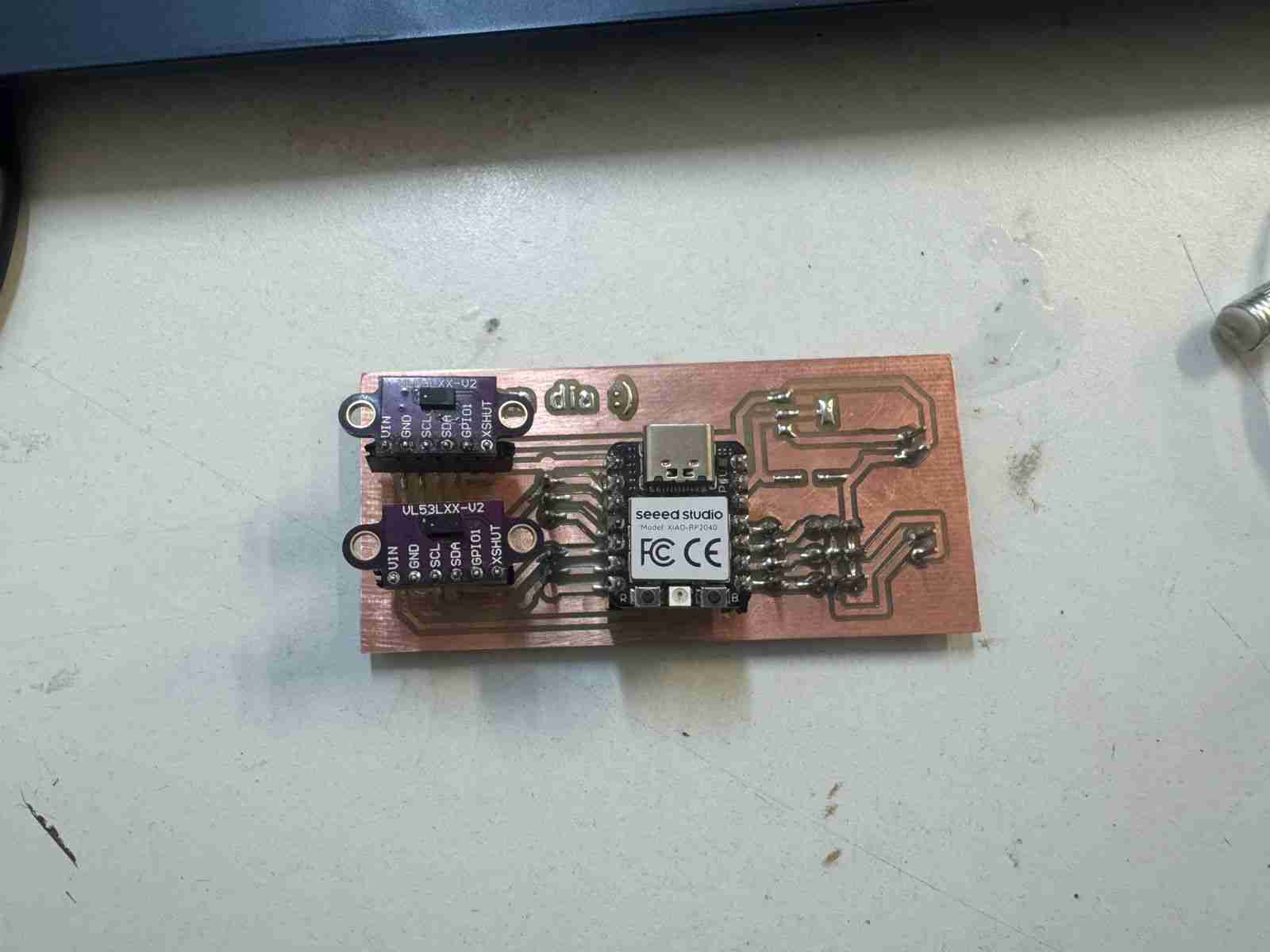
As I also mantioned this type of sensors uses the I2C communication so the diagram of connection is very simple, connect the SDA of the sensor to the SDA of the microcontroller and same for the SCL. in the next picture I will show the pinout from the sensors to the Xiao rp2040.
The SDA and SCL will be connected direct, the VIN of the sensors will be on the 3.3 V pin from the Xiao and the most important pin is the XSHUT thia pin will be connected to the GPIO pin each other, this pin is the responsible for sending the information to the Xiao.
5. Board to use
At first moment I decided ro use the Xiao rp2350 since is the one that the Fab Academy recommended to use but it has a problem with the I2C communications because it uses the pins that are below the board ibstead of the ones that are on the side that are the ones that we commonly used, I tried everyway to use it but it couldn't.
The final solution that my local instructor gave was to use another board and in fact that worked. I used the Xiao rp2040 whach has a similar pinout to the rp2350 but I can work with this one, I was able to code and test the sensor just in five minutes because the code that I did was correct only the rp2350 wasn't letting me use the common I2C pins.
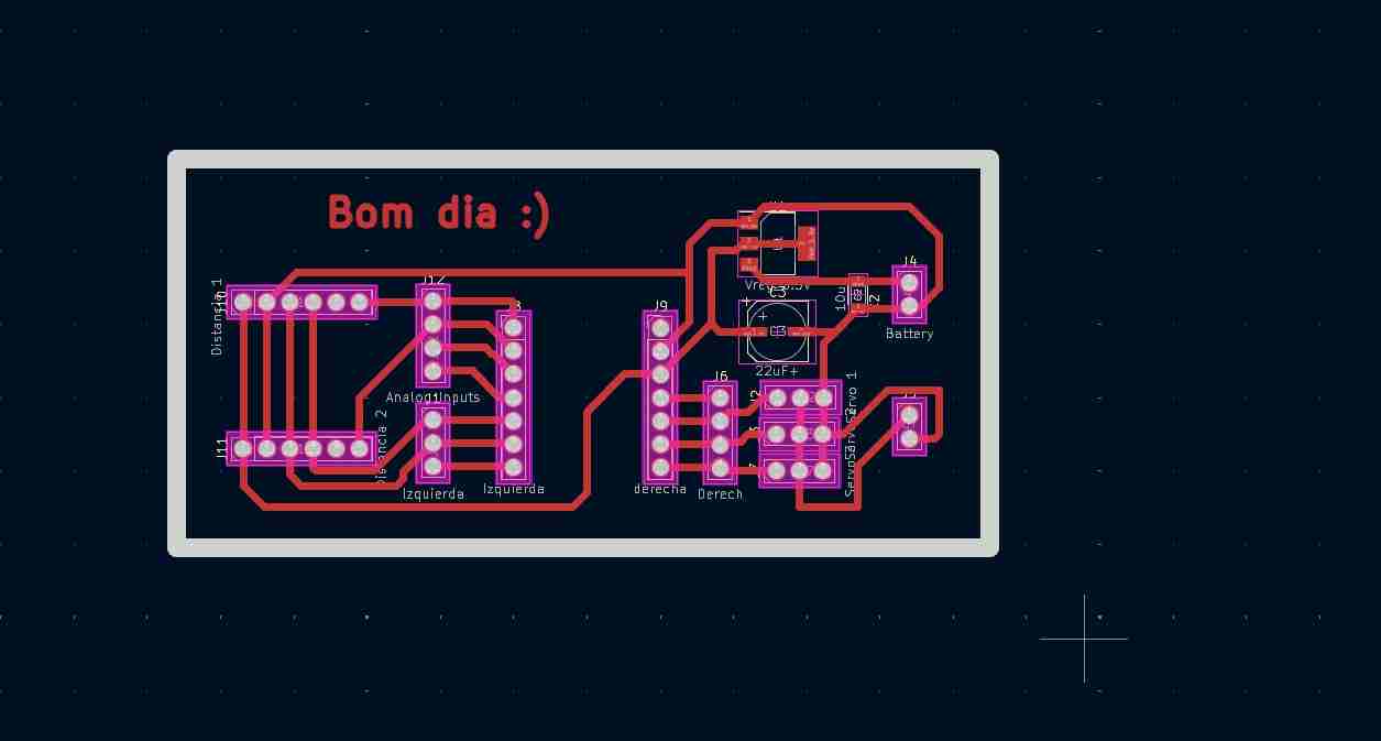
4. Modifying the PCB
I modified the PCB from week 8 moving the servomotors to other pins beacuse they were using the SDA and SCL pins which I needed for the sensors to communicate, I removed the led and button to have more space for fitting the new components. Last but not least I added a new line of pins just in case I need to use them twice instead of just one time.
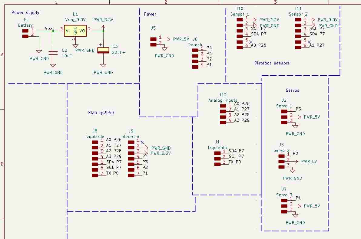
I also have to reorganize the space from the pcb layout.
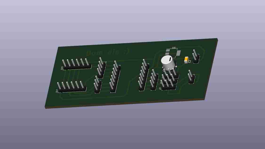
Here is the 3D view of the modified PCB
5. Making the modified PCB
For this step I will repeat the process from week 8 using the Roland Monofab machine and the same tools.
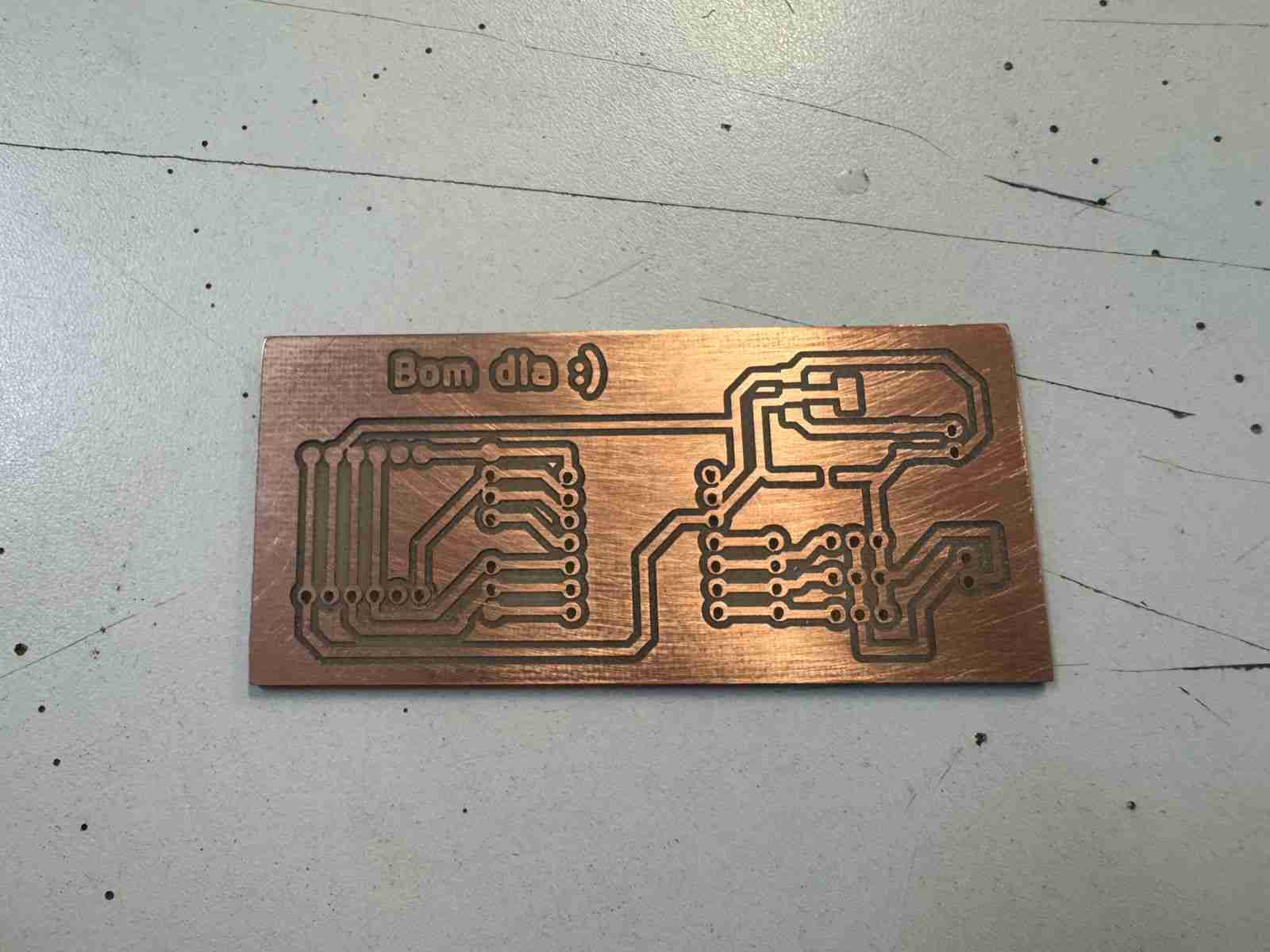
Then we will have to sold the components on it. Is important to notice that I do not sold the voltage regulators and the capacitors because at the moment I will not use and external power source to give energy to the Xiao and I don¿¿'t want to waste those components yet.
6. Making the code
6.1 Defining libraries and objetcs
| Command | Function |
|---|---|
| #include <Wire.h< | Standard library for I2C communication. |
| #include <VL53L0X.h< | Library that we installed at the beginning and that is specific to controlling the distance sensors. |
| VL53L0X sensor1, sensor2 | Two "objects" are created that represent each physical sensor in the code. |
| SHT_LOX1, SHT_LOX2 | The digital pins (26 and 27) are defined and connected to the XSHUT pins of the sensors. These function as an on/off switch. |
6.2 Setup
| Command | Function |
|---|---|
| pinMode(..., OUTPUT) | Configure the control pins as outputs. |
| digitalWrite(..., LOW) | Puts both sensors into standby mode (off). |
6.3 I2C Bus Initialization
| Command | Function |
|---|---|
| Wire.setSDA(6), Wire.setSCL(7) | Define which physical pins will be used for the data (SDA) and clock (SCL) of the I2C bus. |
| Wire.begin() | Communication begins on the bus. |
6.4 Dynamic Address Assignment
We will repeat the process for both sensors.
| Command | Function |
|---|---|
| digitalWrite(SHT_LOX1, HIGH) | Turn on only the first sensor. |
| sensor1.init() | It starts with the factory address (0x29). |
| sensor1.setAddress(0x30) | It is immediately ordered to change its address to $0x30$, so that now sensor 1 will no longer respond to the original address. |
6.5 Loop cycle
| Command | Function |
|---|---|
| readRangeSingleMillimeters() | It sends out a laser pulse, measures the time it takes to return, and returns the distance in millimeters. |
| uint16_t d1, d2 | Stores values in unsigned 16-bit integer variables. |
| Serial.print | It sends the results to the computer's serial monitor so you can view them in real time. |
| delay(100) | Pause execution for 100 milliseconds to avoid saturating the serial port and to stabilize the readings. |
Here is the complete code:
                    #include <Wire.h<
                    #include <VL53L0X.h<

                    //Definimos objetos
                    VL53L0X sensor1;
                    VL53L0X sensor2;

                    //Pines XSHUT (encienden sensores)
                    #define SHT_LOX1 26 // D0
                    #define SHT_LOX2 27 // D1

                    void setup() {
                    Serial.begin(115200);

                    //Pines XSHUT como salida
                    pinMode(SHT_LOX1, OUTPUT);
                    pinMode(SHT_LOX2, OUTPUT);

                    // 1.Estado inicial
                    digitalWrite(SHT_LOX1, LOW);
                    digitalWrite(SHT_LOX2, LOW);
                    delay(10);

                    // 2.Iniciar I2C
                    Wire.setSDA(6);
                    Wire.setSCL(7);
                    Wire.begin();

                    // 3.Configuracion sensor 1
                    digitalWrite(SHT_LOX1, HIGH); // Prendemos el 1
                    delay(10);
                    sensor1.setTimeout(200);
                    if (!sensor1.init()) {
                        Serial.println("Fallo al iniciar sensor 1");
                    }
                    sensor1.setAddress(0x30); //Escogemos direccion nueva

                    // 4.Configuracion sensor 1
                    digitalWrite(SHT_LOX2, HIGH); //Prendemos el 2
                    delay(10);
                    sensor2.setTimeout(200);
                    if (!sensor2.init()) {
                        Serial.println("Fallo al iniciar sensor 2");
                    }
                    sensor2.setAddress(0x31); //Escogemos otra dirección para sensor 2

                    Serial.println("Sensores configurados con direcciones 0x30 y 0x31");
                    }

                    void loop() {
                    // Lectura Sensor 1
                    uint16_t d1 = sensor1.readRangeSingleMillimeters();
                    // Lectura Sensor 2
                    uint16_t d2 = sensor2.readRangeSingleMillimeters();

                    Serial.print("S1: "); Serial.print(d1); Serial.print("mm | ");
                    Serial.print("S2: "); Serial.print(d2); Serial.println("mm");

                    delay(100);
                    }
7. Results
Here is the code working at the recieving the distance from the sensors connected in the PCB.
8. Files created
Click on the "Download ZIP" to download all the files I made for this week assignment