Week 8. Electronics production
Summary
This week we focused on learning how to use the endmill machine so we can make our own pcb for whatever purpose we want, this week reuses topics that we saw on week 4.
Group assignment
Here is the group assignment to check more information about the topic electronics production.
1. Basic concepts
1.1 What is a mini CNC?
It's a 3-axis (X, Y, Z) milling machine that uses subtractive machining. Essentially, a rotating milling cutter cuts material while the workpiece moves along the X, Y, and Z axes, controlled by a computer.
1.1.1 Why is it useful?
- PCBs (electronic boards)
- Mechanical prototypes
- Small molds
- Engraving and carving
1.2 What is solding?
Soldering is the process of joining two pieces using a molten metal, called solder, which solidifies upon cooling and holds them together. In the current topic, soldering means heating tin with a soldering iron to join the pins of a component to the traces on a PCB, creating a mechanical and electrical connection.
1.2.1 Materials that you must have for solding
- Tin: It usually comes as solder wire, which, when heated with a soldering iron, melts and electrically and mechanically joins the components to the tracks of a PCB.
- Soldering Iron: An electric tool that heats up to melt solder and allow components to be joined to the PCB.
- Soldering iron stand: A base where the hot soldering iron is safely placed when not in use.
- Flux: A substance that cleans the metal surface and improves solder adhesion, preventing faulty solder joints.
- Sponge or Tip Cleaner: Used to clean the soldering iron tip while working and maintain good heat transfer.
- Tweezers: Allow you to hold small components or place them on the PCB without getting burned.
- Desoldering braid or desoldering pump: Tools used to remove excess solder or correct soldering errors.
2. Exporting our files from Ki Cad
Before using the monofab we need to exporte our files from Ki Cad so we can drill, engrave and cut our pcb.
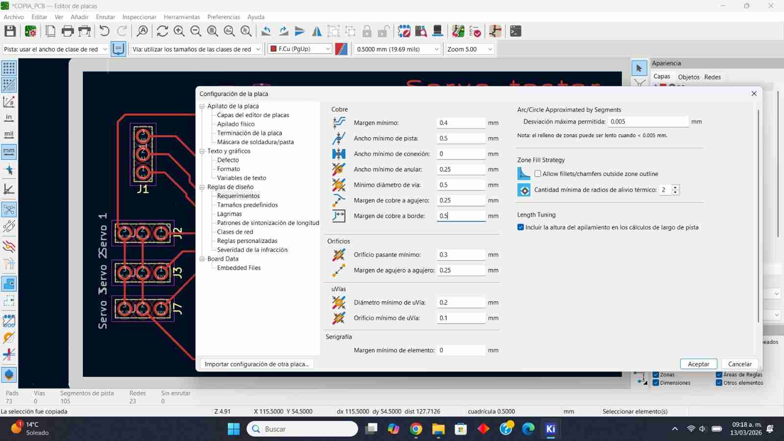
2.1 Making small changes
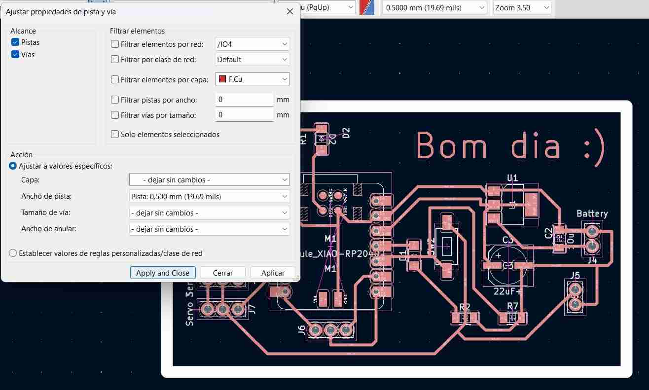
2.1.1 Modiying the width of my tracks
Before exporting out files I made some changes to the pcb I made on week 4, I made changes to the width of the track because I hadn't previously considered the mill bit to be used, so I was only "cutting ideally", changing my width to 0.5mm.
To apply the change to all tracks, press "shift+a" (select all), then go to edit, edit track and track properties, change your track width to 0.5 and click on "apply and close".
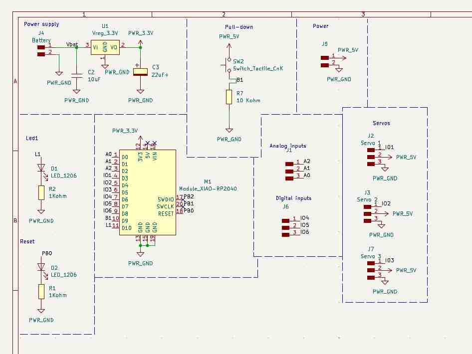
2.1.2 Adding pins to the pcb
I modified the outputs so I could test 3 servomotors at the same time and left the other inputs free in case I wanted to use them.
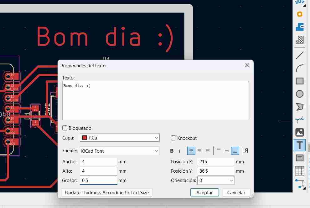
2.1.3 Add text to the pcb
This is just in a decorative way. To add text, click the button with the "T" logo, write what you want, and adjust the size. The recommendation is to use a square size so it looks good.
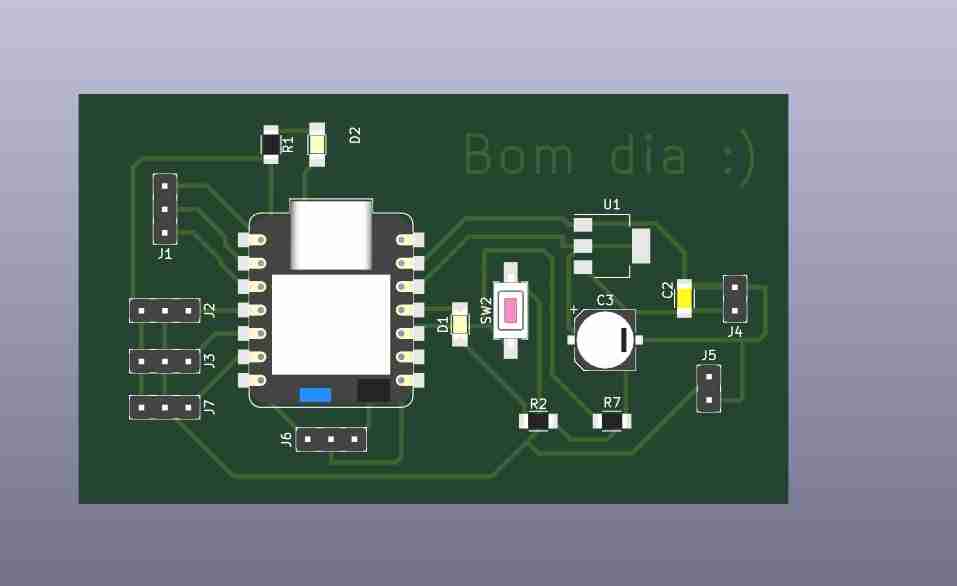
2.2 Final 3D view of my pcb
Here is how I my pcb should look like ince it is finished.
2.3 Export your files from Ki Cad
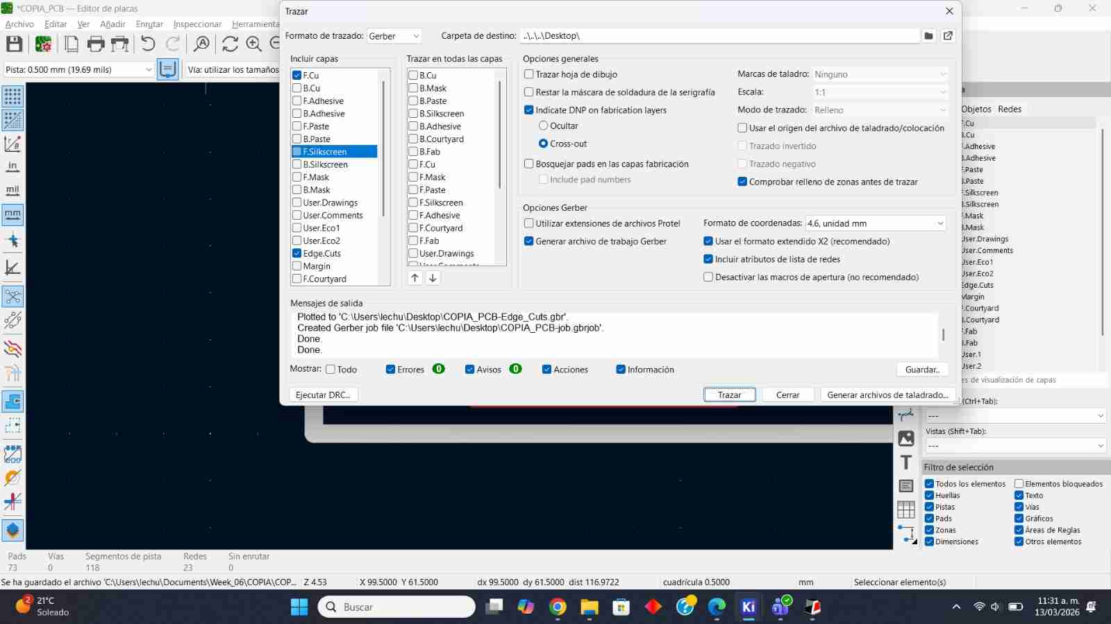
Once you have done your changes, corrections and modifications you should go to File, Factory Outputs, Gerber, select SVG plot and plot.
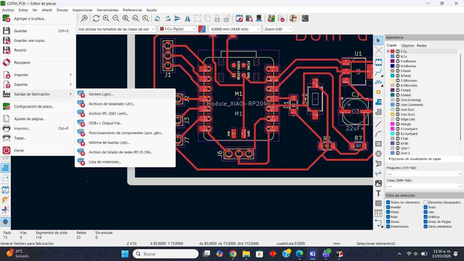
Select only the layers that we have used in the PCB file, in my case F.Cu, User.Drawings and Edge.Cuts.
3. Saving the files to the monofab formmat
The Roland MonoFab SRM-20 (and other Roland milling/cutting machines) accepts RML files because this is Roland's native command format that defines the machine's paths and movements.
3.1 Open the mods CE page
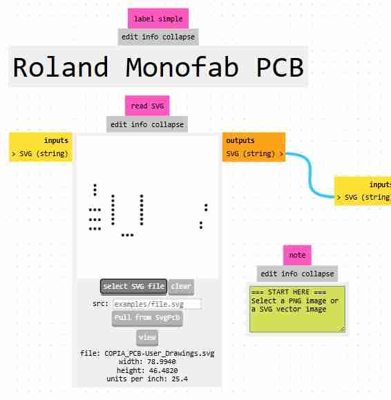
The Mods CE is a page that converts SVG or PNG files to rml files so the milling/cutting machines can make what you want. You acces by clicking on the previous link or by searching roland monofab CE it will normally be the 1st or 2nd link.
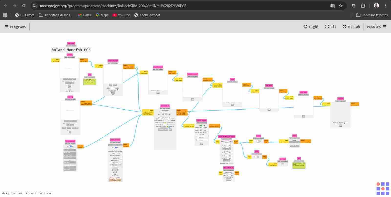
Search for the machine that you have, in my case it will be the Roland Monofab PCB
3.2 Select your SVG or PNG
Once you have selected your machine you will upload one file, is important to follow this workflow for obtaining better results holes, engrave, cutting.
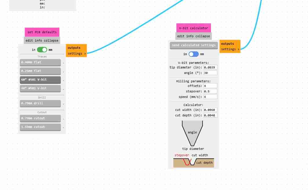
3.3 Select the tool
We have 3 options for the tool trace, drill and cutout. Depending on what we need we will select each function, in my case I'm doing the holes so I will select drill and it will automatically make the maths to send the instructions to the machine, in this part we will change the tool diameter for the ones that we have physically (my case will be 0.89 for hole and 2 for cutting). We can also specify how mane offsets we want the machine to do (the offsets are the nomber of times the machine will repeat the instruction) for the holes and cutting I personally recommend 1
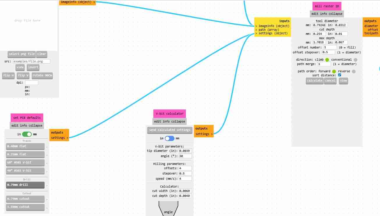
We can modify the speed at which the tool operates, which is recommended to be between 2 and 4 mm/s, and finally, we must activate the "outputs, save files" option so that our rml file is downloaded when we click on calculate.
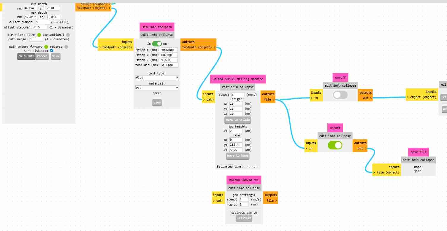
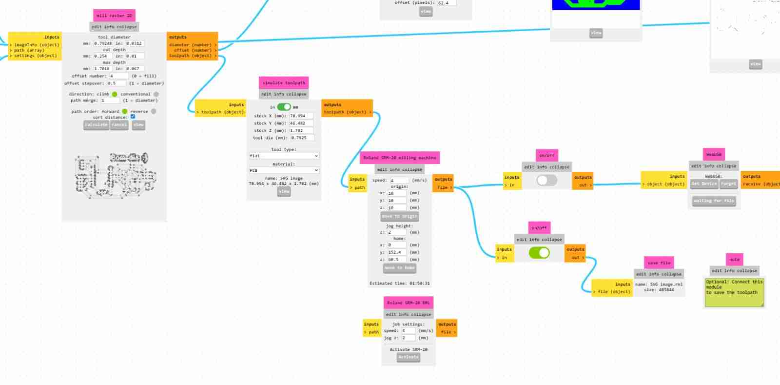
3.4 Download you file
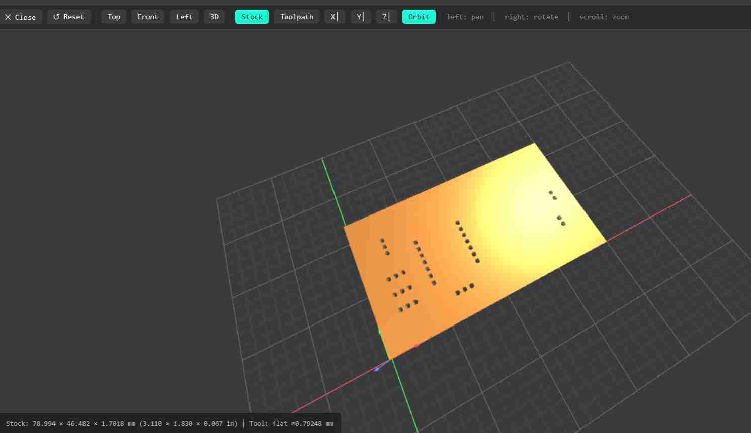
Click on calculate to download your file and also thw page will open a new tab in which you will what the rml file will do.
You will repeat this process with the cutting and engravig. Except that on the engraving option you will change the tool and the number of offsets, being that the tool will be the one of 60° and the offsets will be 4 to prevent our traces from having copper burrs, because it's a mistake that happened to me and I had to sand my PCB more than expected.
At the end we will have 3 files for using the machine.
4. Using the monofab
Once we have all our files we can start using the monofab, but firts we will have to install the program.
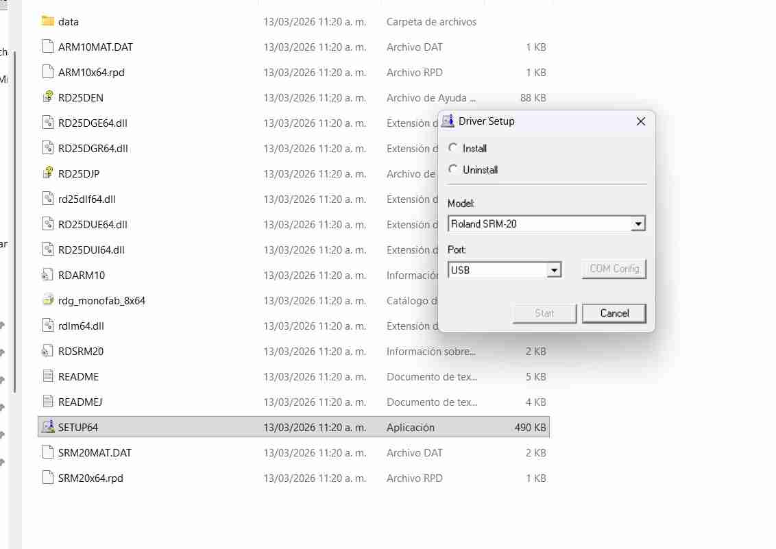
4.1 Download the program
My local instructor gave us the program to download it. We installed the program provided by our instructor and selected the endmill model.
This is the program window.
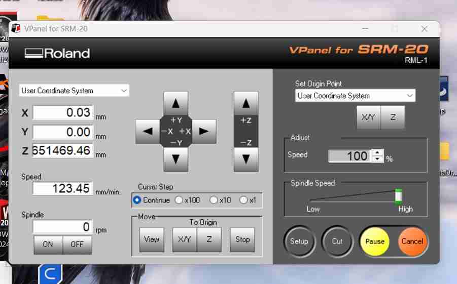
4.1.1 What each button does
- View: Shows us the plate.
- XY and Z: Go to where the machine is, but we won't use them because we could break the bit.
- x100, x10, x1: Lowers more slowly the tool.
We also make it lower until it produces dust, similar as we did with the CNC from week 7.
For executing our rml files we click on Cut, then add file and select the rml file, then click on output and it will automatically start drilling, cutting or engraving.
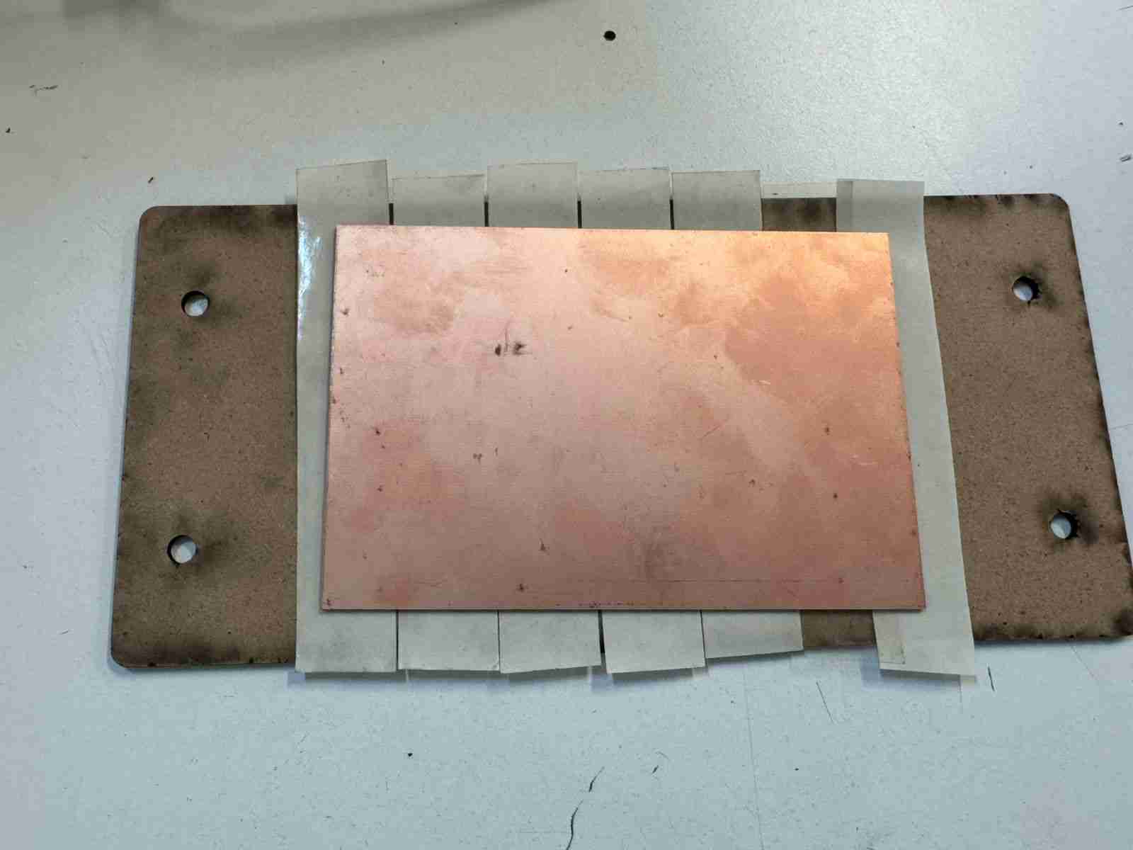
4.2 Preparing the pcb
Similar to the CNC in week 7, we will have our working material, the PCB and the sacrificial bed.
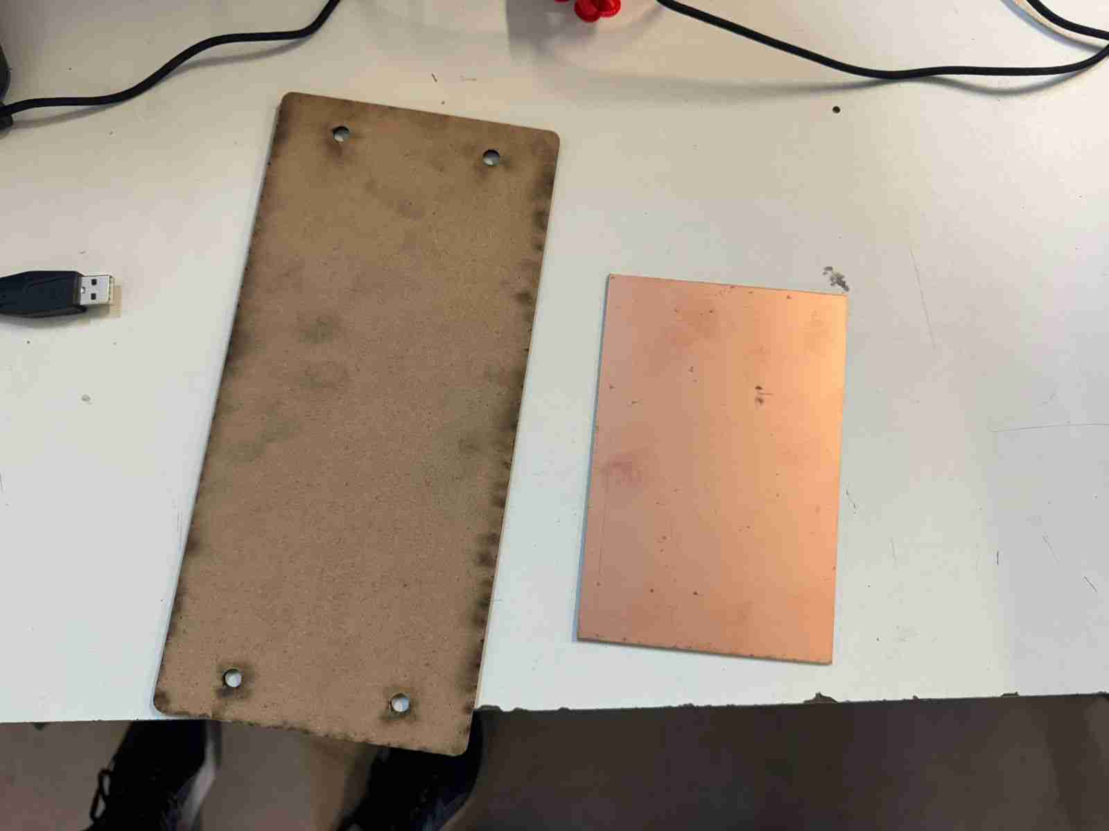
We attached the PCB to the bed with double-sided tape so that it wouldn't move when the tool was on it.
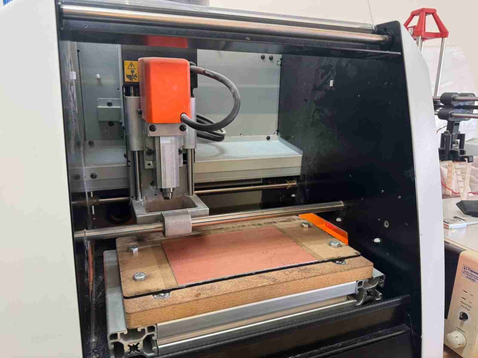
4.3 Preparing the machine workspace
This is the workspace of the machine.
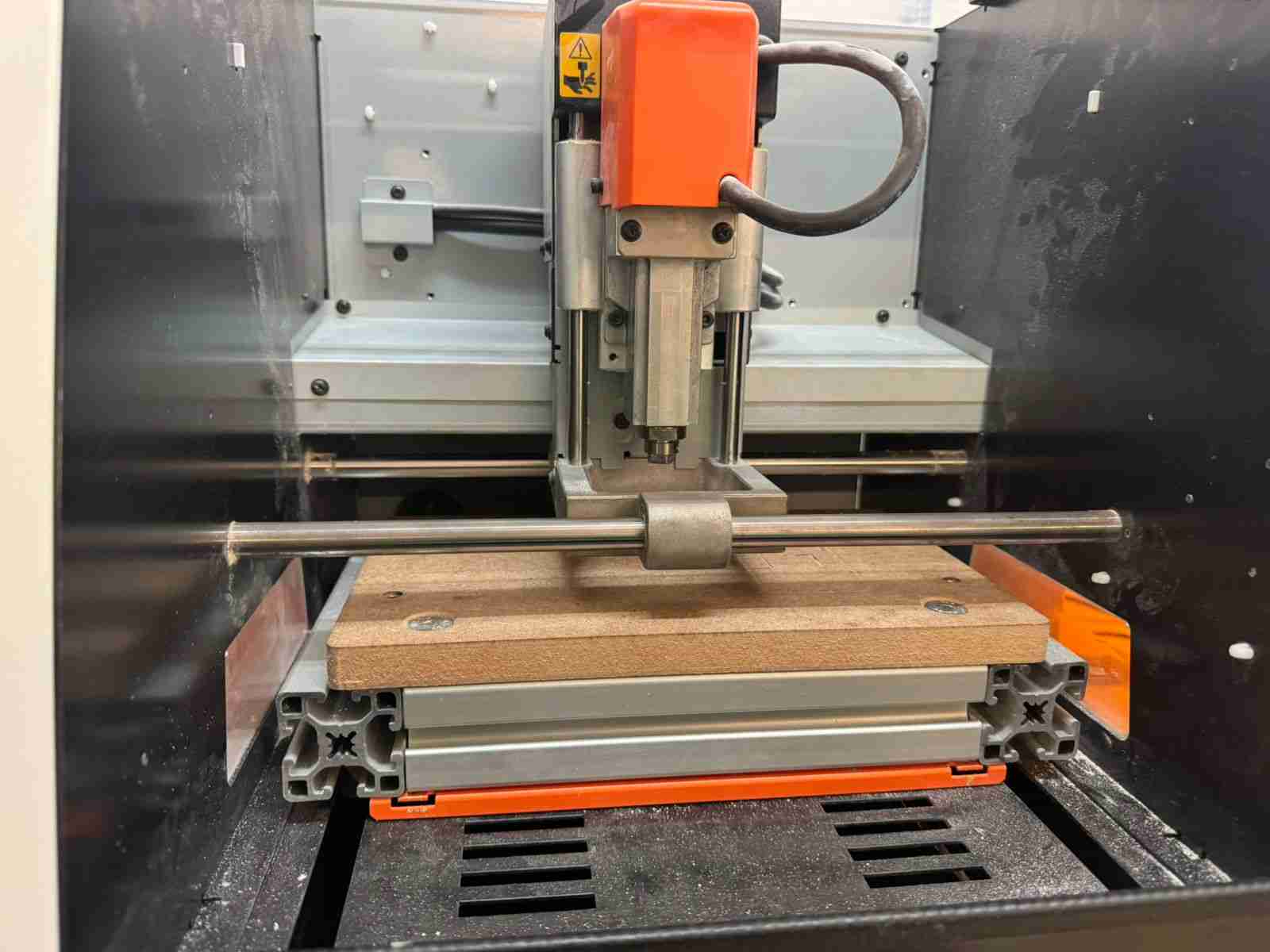
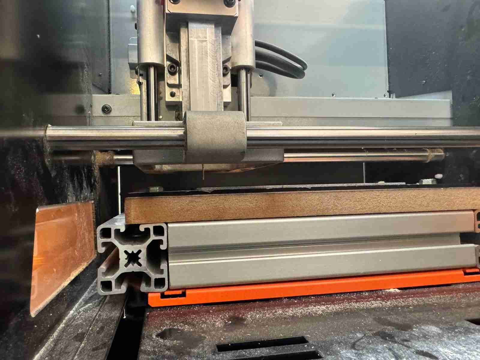
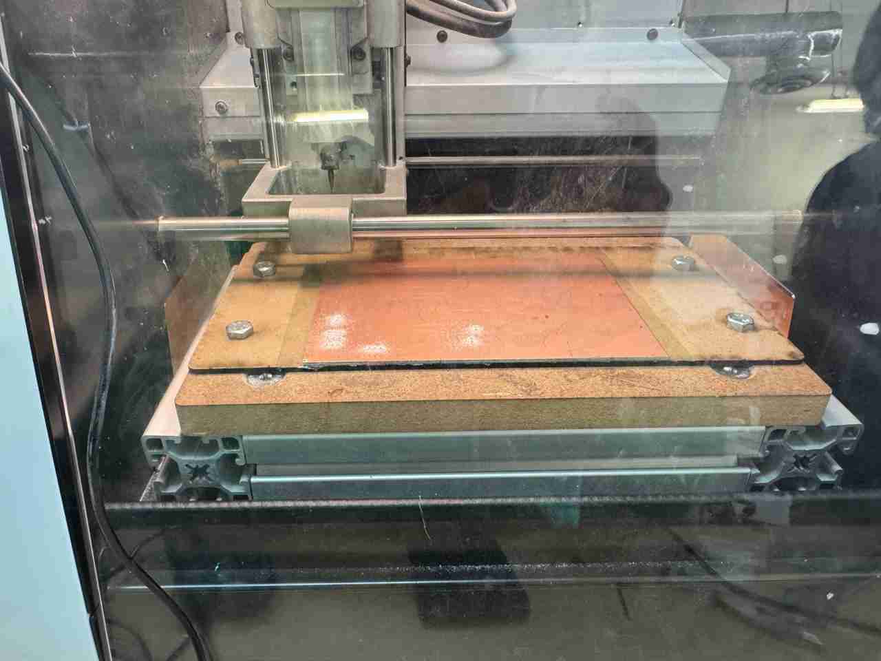
4.3.1 Screw our sacrificial bed together
We bolted down our bed so that it wouldn't move while we were working.
At the end it has to look like this.
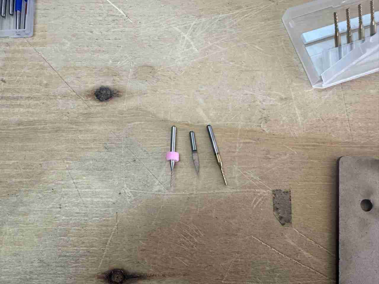
4.3.2 Bits to use
These are the bits and mill bit to use, the ones for holes and cuts being the same, only changing the radius (smaller hole, larger cut) and the mill bit is the engraving tool that looks like a needle.
To change the bits, we use an Allen wrench that loosens our bits bit by lowering it. Once it's lowered, we replace it with the bit we need. In our case, the bit bit can rise quite high, even to the point of being completely submerged. My recommendation is to insert the bit halfway or slightly less than its length, tighten the screw, and that's it.
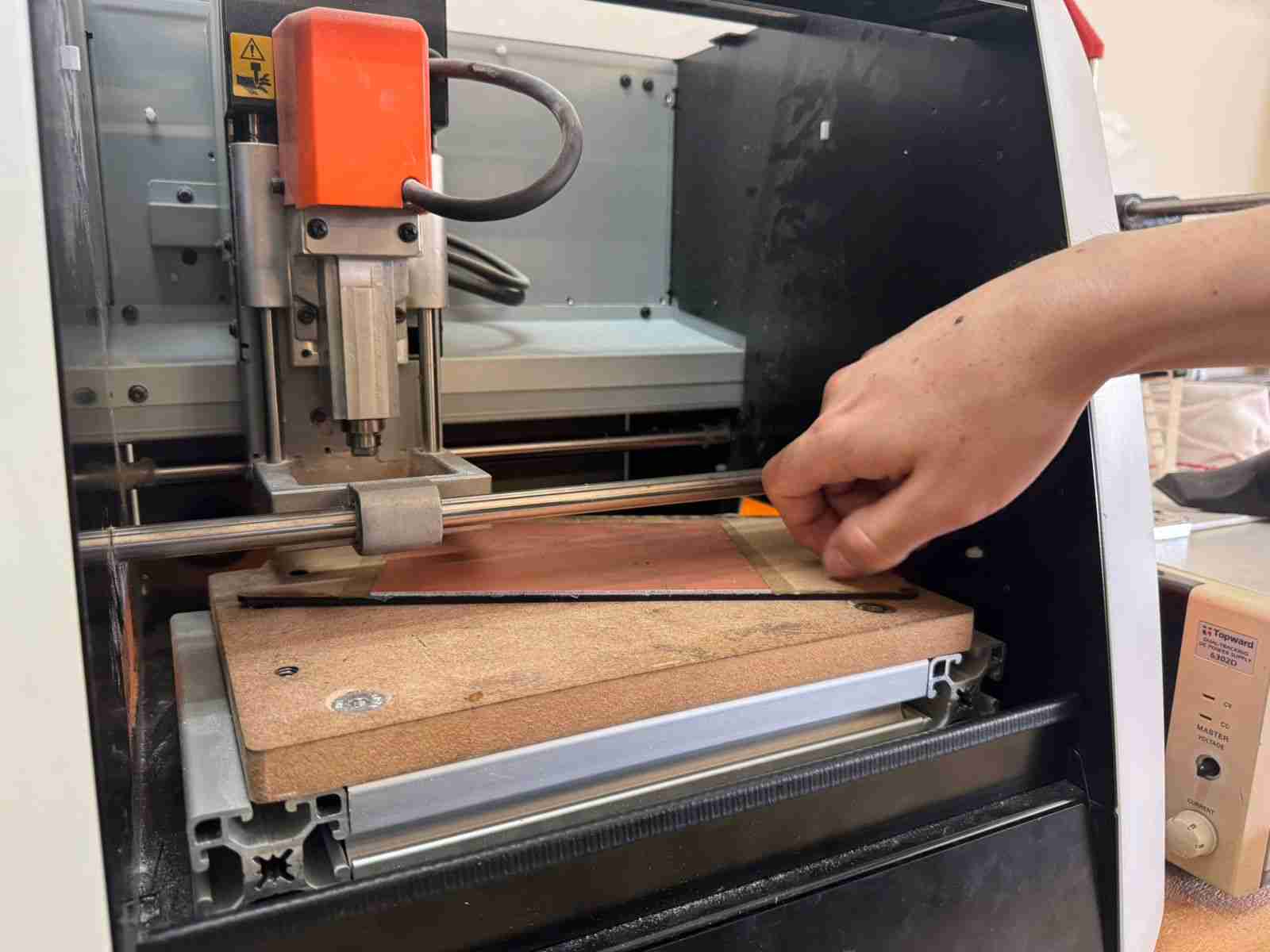
4.4 Execute the files
Now that all is set up we can run our files, starting with the holes.
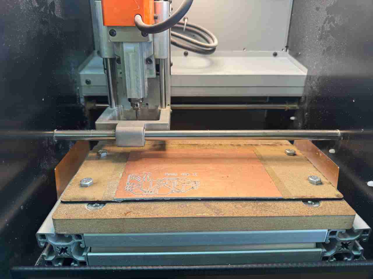
4.4.1 Holes
As I already mention I will follow this workflow hole, engrave and cut.
After each work dust from the cutted PCB is generated so we have to clean when our rml file is done so we can execute the next file.
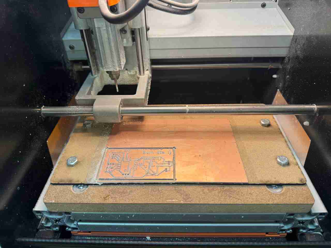
4.4.1 Engrave
4.4.1 Cuts
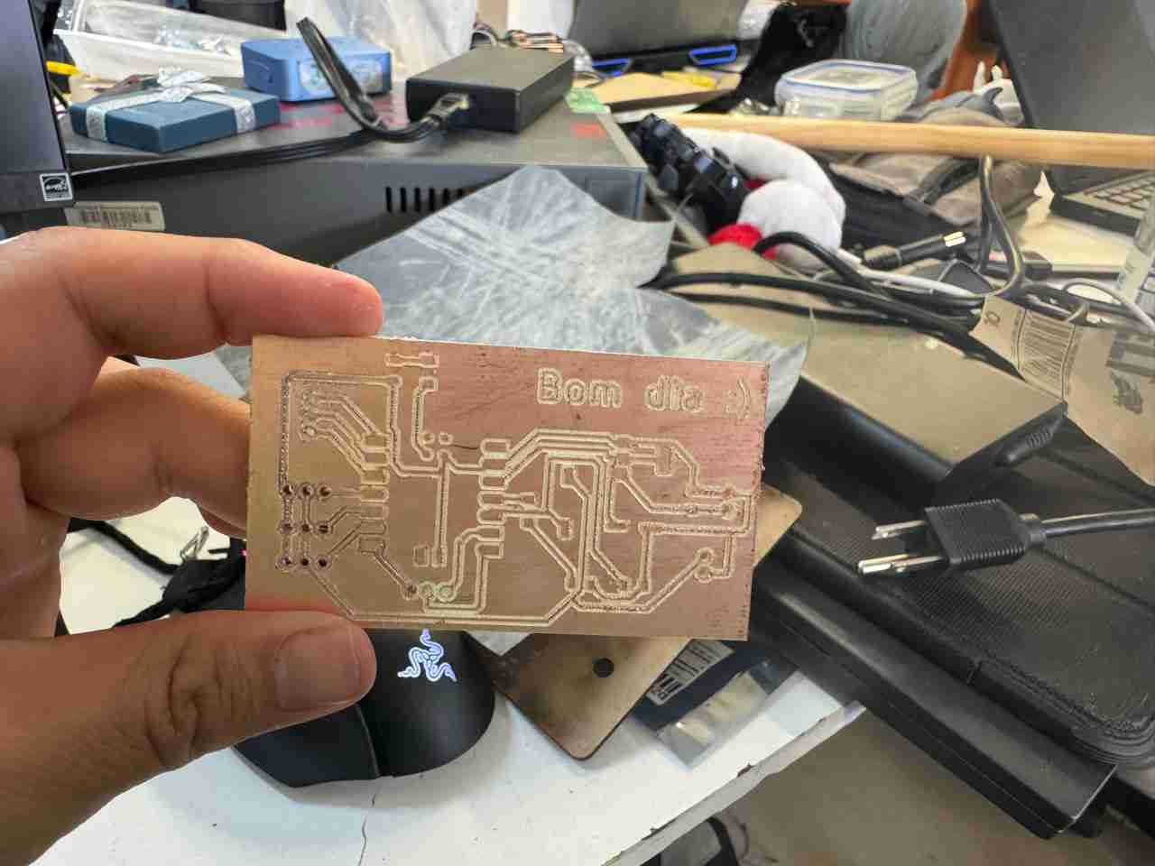
4.5 Result
Here is the final result after sanding and ready to satrt solding.
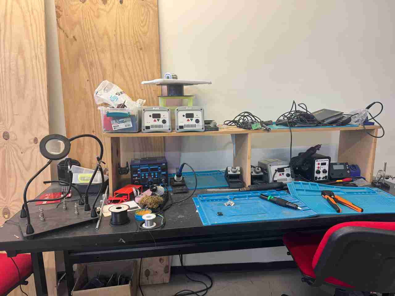
5. Solding
Last we have to sold the components that were in our Ki Cad files. This is our workspace here at Ibero Puebla.
4.1 Add flux
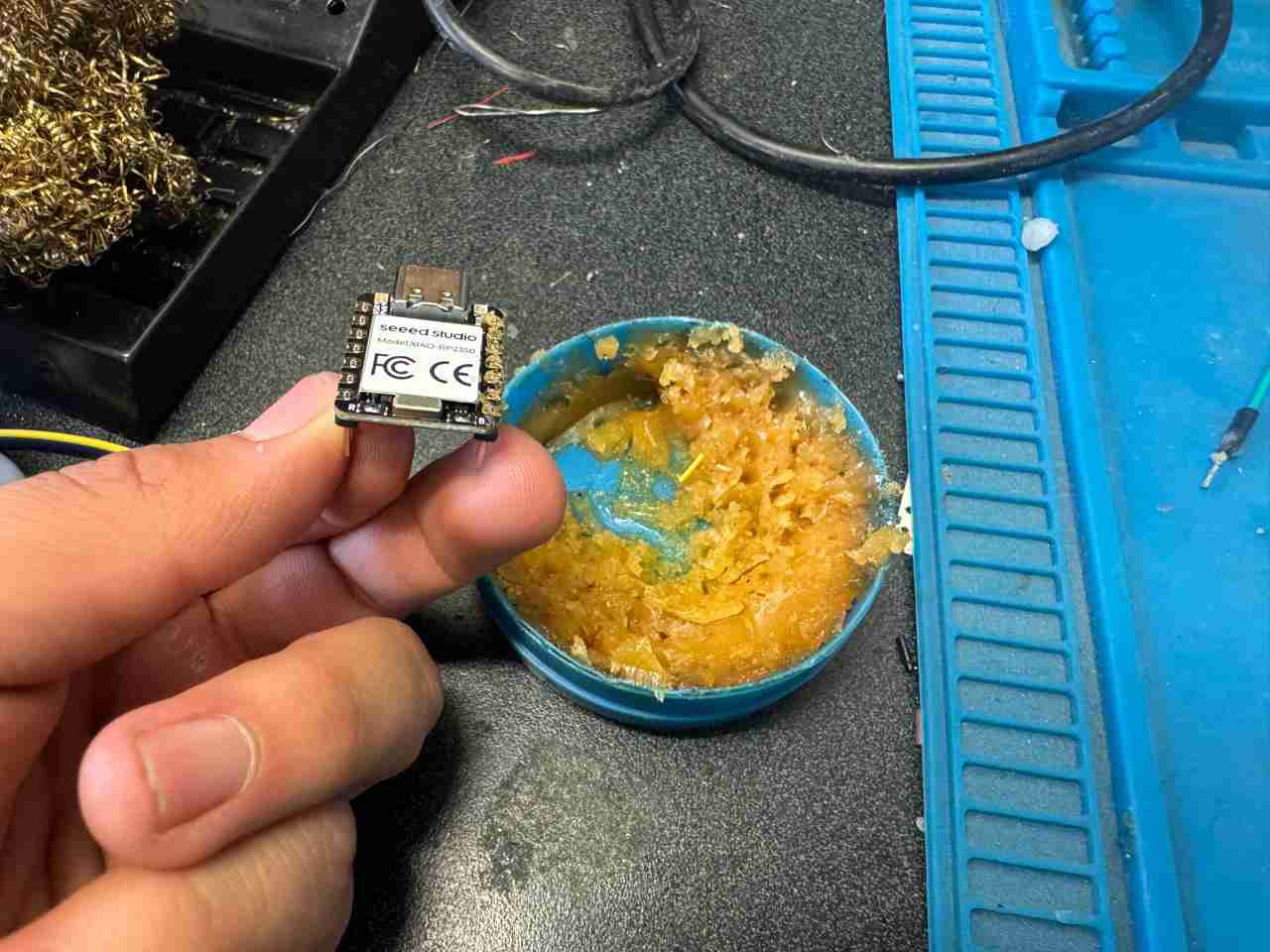
For solding in a better way we will aplly flux to each solding zone, like in the image in that way the heat it dissipates heat better, resulting in a more uniform and cleaner solder joint.
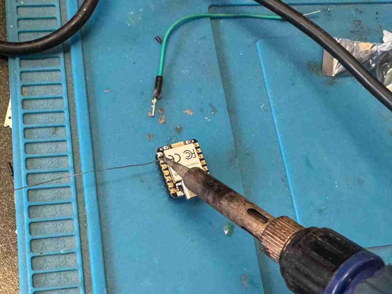
4.2 Start solding
We will put the tin and the soldering iron together in the place where we applied the flux.
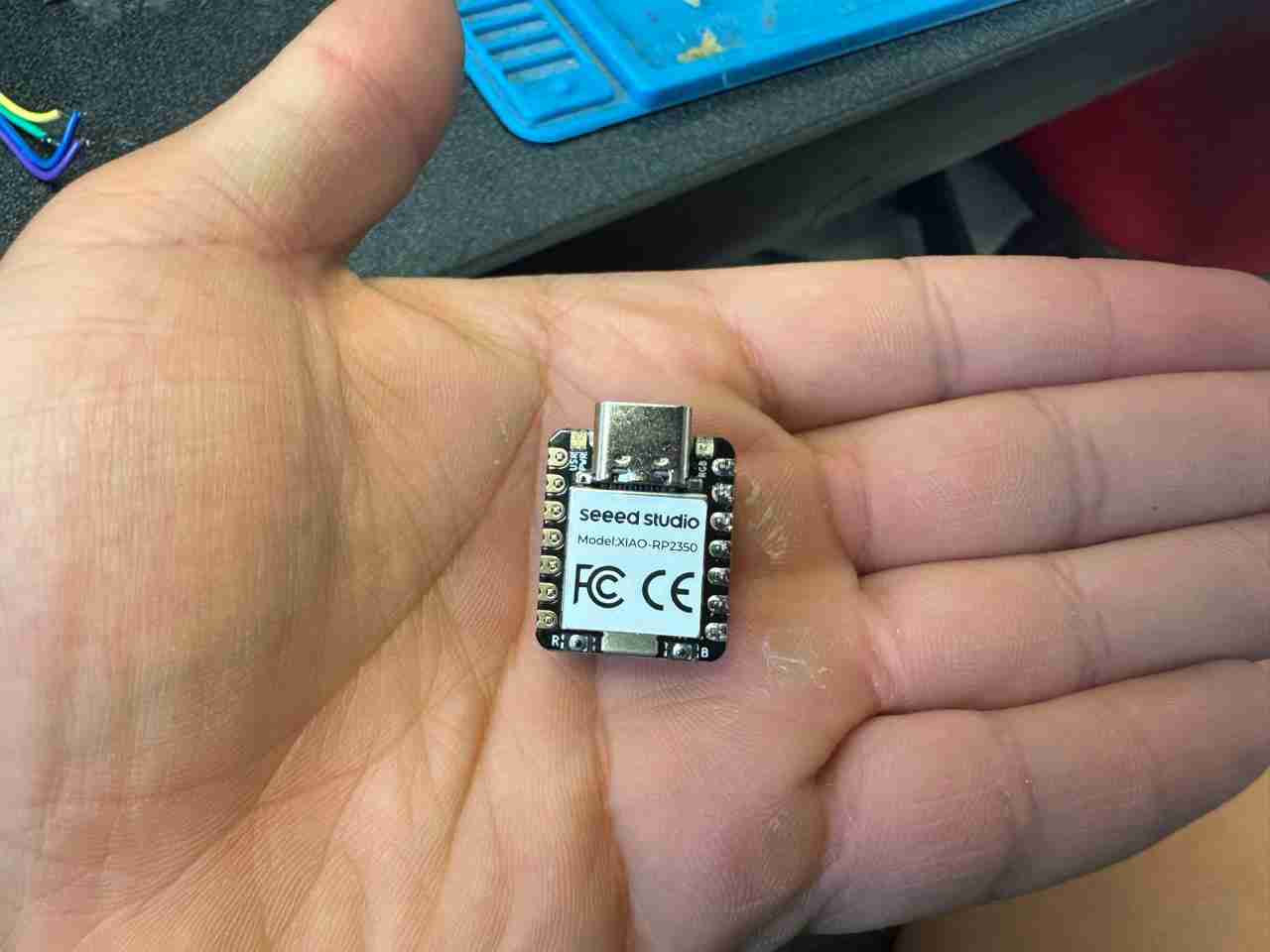
Here is a comparisson of how it looks soldered against not soldered.
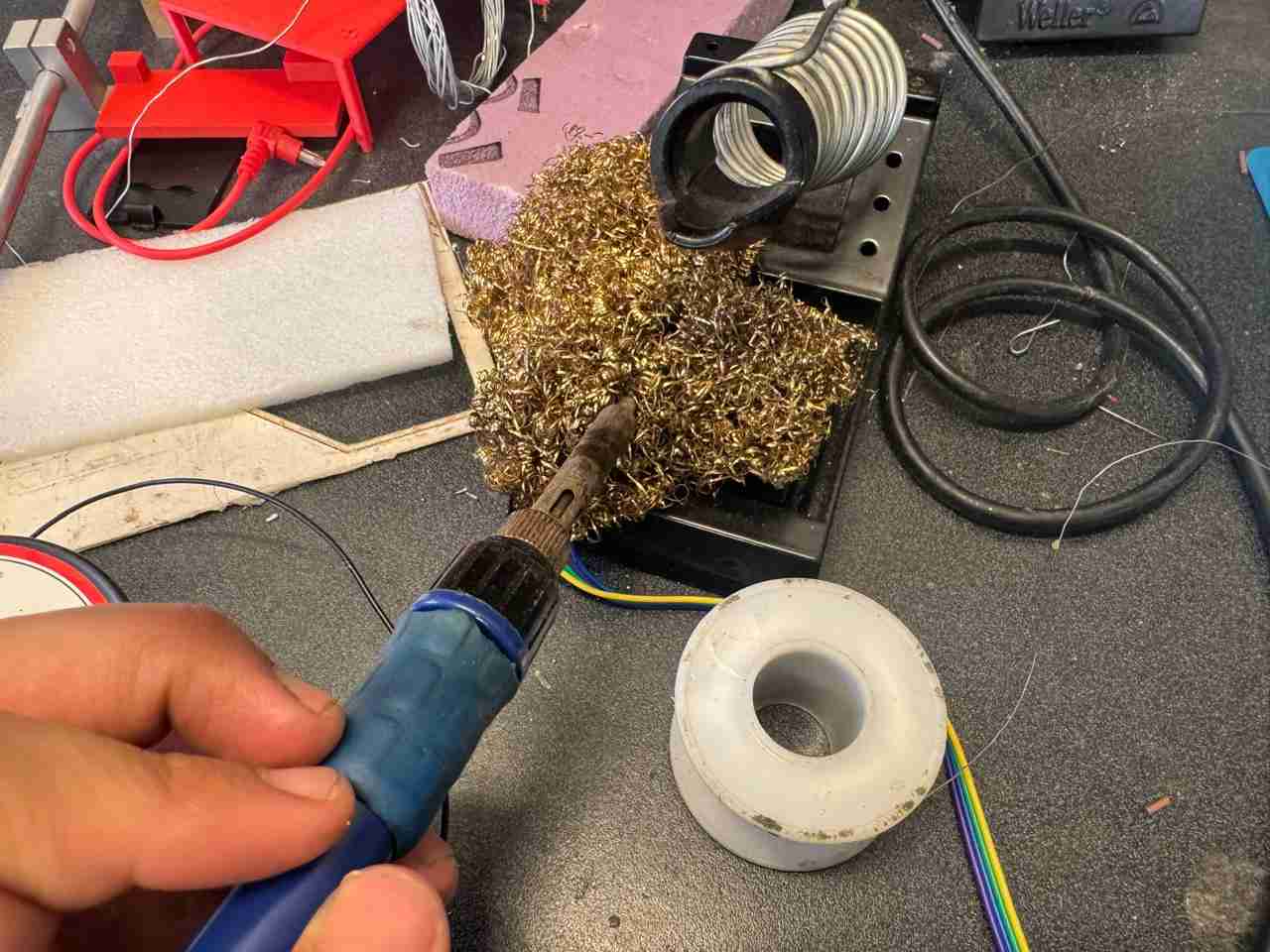
4.3 Clean you soldering iron
You have to clean your soldering iron with a sponge or a metallic fiber to remove the excess of tin from the tip.
This is the process that you have to repeat for each component until you have finished.
4.5 Positive and negative
The electrolytic capacitor and LED have a way of identifying which is positive and which is negative.
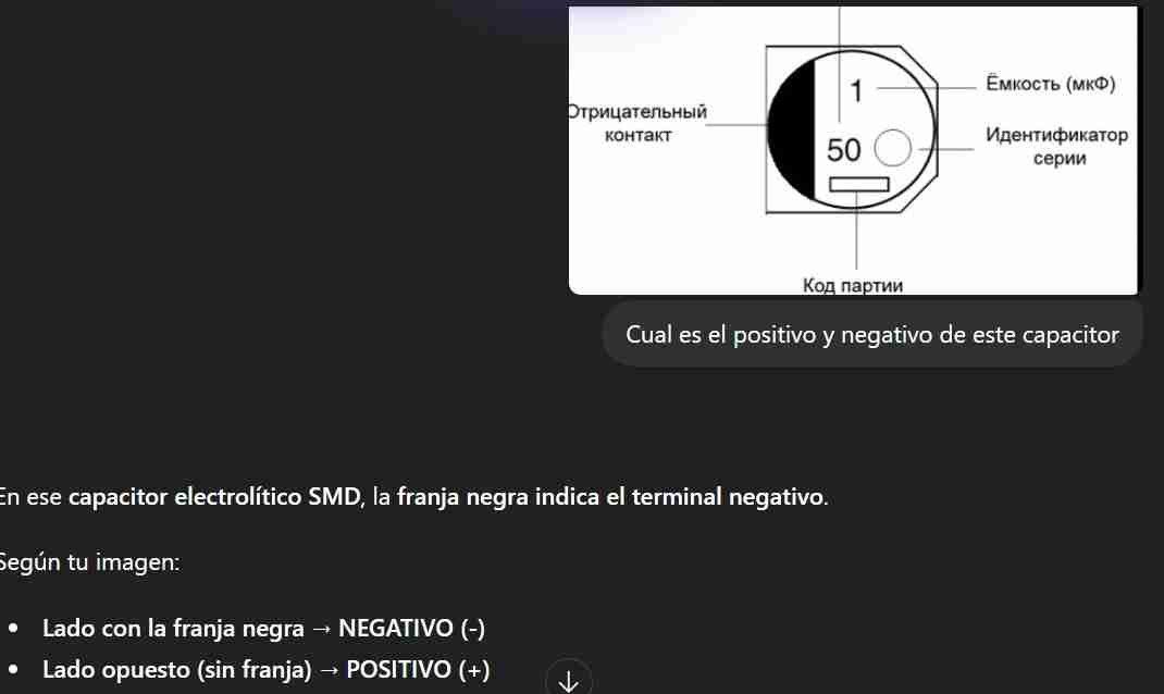
4.5.1 Electrolytic capacitor
The positive is the side with no black paint and the negative is the side with black paint.
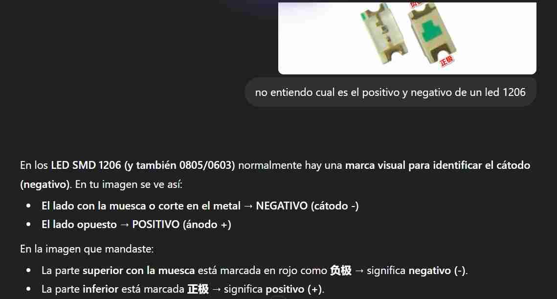
4.5.2 LED
The positive is the side with the flat side of the T.
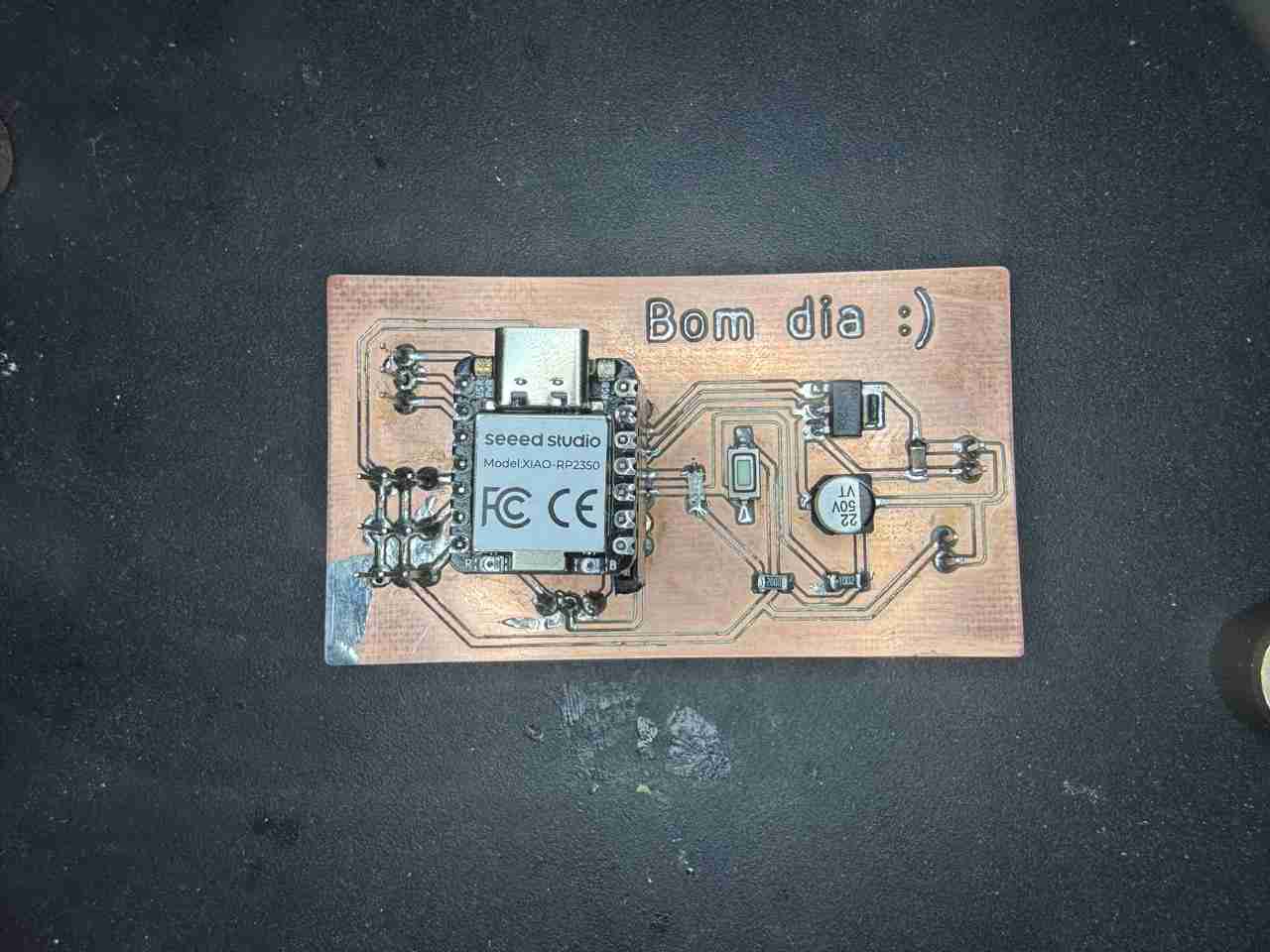
Here is my PCB already soldered.
6. Results
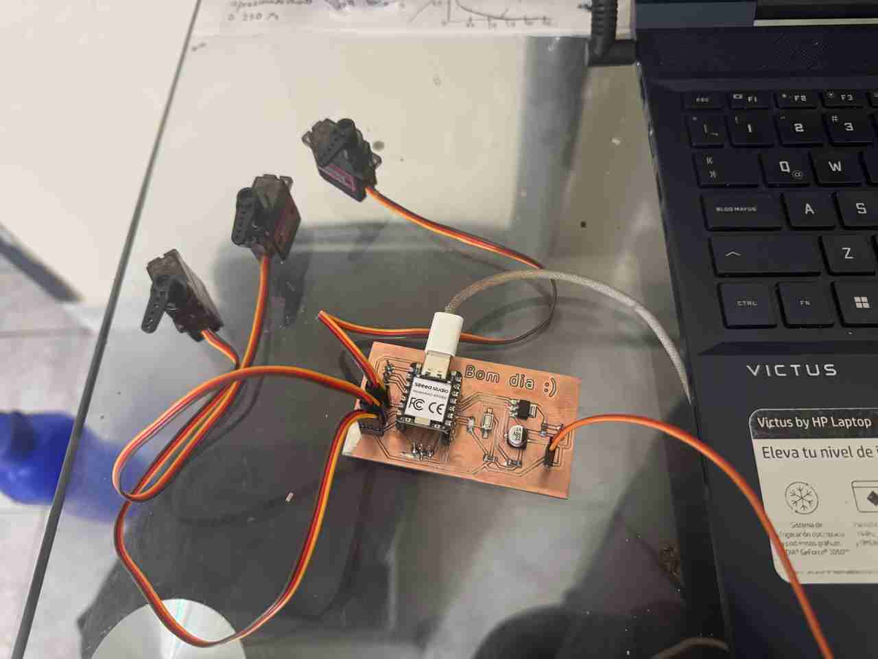
Here is how it looks the pcb with the servos attached.
Here is the code used for testing the PCB functionality.
                from machine import Pin, PWM
                import time
                import sys
                import uselect

                SERVO1_PIN = 6    # USAR GPIO
                SERVO2_PIN = 7
                SERVO3_PIN = 5
                LED_PIN    = 3
                BTN_PIN    = 4

                # Parámetros de los Servos
                SERVO_MIN_US = 500
                SERVO_MAX_US = 2500
                SERVO_HZ = 50
                PERIOD_US = 1_000_000 // SERVO_HZ

                servo1 = PWM(Pin(SERVO1_PIN), freq=SERVO_HZ)
                servo2 = PWM(Pin(SERVO2_PIN), freq=SERVO_HZ)
                servo3 = PWM(Pin(SERVO3_PIN), freq=SERVO_HZ)

                led = Pin(LED_PIN, Pin.OUT)
                boton = Pin(BTN_PIN, Pin.IN, Pin.PULL_UP)

                # Configuración de lectura de terminal (sin bloqueo)
                spoll = uselect.poll()
                spoll.register(sys.stdin, uselect.POLLIN)

                def mover_servo(servo, angulo):
                    us = int(500 + (angulo * 2000 / 180))
                    duty = (us * 65535) // 20000
                    servo.duty_u16(duty)

                # Variables de estado
                last_btn_state = 1
                print("Sistema listo, formato: ID, angulo")

                while True:
                    btn_val = boton.value()
                    if btn_val == 0 and last_btn_state == 1:
                        led.value(not led.value())
                        time.sleep_ms(50)
                    last_btn_state = btn_val

                    if spoll.poll(0):
                        raw_data = sys.stdin.readline().strip()
                        try:
                            partes = raw_data.split(',')
                            if len(partes) == 2:
                                idx = int(partes[0])
                                ang = int(partes[1])

                                if 0 <= ang <= 180:
                                    if idx == 1:
                                        mover_servo(servo1, ang)
                                    elif idx == 2:
                                        mover_servo(servo2, ang)
                                    elif idx == 3:
                                        mover_servo(servo3, ang)
                                    print(f"S{idx} -> {ang}")
                        except:
                            pass

                    time.sleep_us(100)
Here are the both tests, the servos and the led with the button.
7. Files created
Click on the "Download ZIP" to download all the files I made for this week assignment