Week 4. Embedded Programming
Summary
This week we focused on the basics of programming and connecting using simulators like Wokwi and learning some lenguages like C++ and python. The objective of this week was to programm and test a wiring diagram in a simulation page or software.
Group assignment
Here is the group assignment to check more information about the topic embedded programming.
1. Basic concepts
1.1 What is embedded programming?
It is the programming of embedded systems: devices where the software runs inside a microcontroller or microprocessor to control specific hardware (sensors, motors, communications, etc.) and perform a specific function. It works directly with peripherals (GPIO, ADC, PWM, I2C, SPI, UART), has limited resources (memory, CPU, power) and usually requires knowing its behavior in real time (precise timing, fast response).
1.2 What is a lenguage programming
Programming languages are formal systems (with rules of syntax and meaning) that allow you to write instructions for a computer or microcontroller to perform tasks. They are used to express logic (conditions, loops, functions), manipulate data, and control resources (memory, files, networks, or hardware). These instructions are then interpreted or compiled into a format that the machine can execute.
1.2.1 Types of programming languages
C++
C++ is a compiled programming language, derived from C, that adds object-oriented programming features (classes and objects) and other enhancements. It is widely used when you need high performance and direct control over hardware and memory, which is why it is common in embedded systems like Arduino/ESP32, video games, and high-performance software.
Python
Python is a high-level programming language, easy to read and widely used for automation, data analysis, web development, and scripting. In microcontrollers, it is primarily used in adapted versions such as MicroPython or CircuitPython, which allow programming hardware with Python syntax. Commonly used with Raspberry Pi Pico (RP2040), STM32, nRF52 with MicroPython and CircuitPython depending on what is used.
1.3 What are libraries?
They are a package of pre-built code (.h and .cpp files) that encapsulate common functions to avoid rewriting them (drivers, protocols, peripheral control). They provide a simple API ("ready-made functions") to perform complex tasks with just a few lines of code. This reduces typical errors and accelerates development (because the code has already been tested by many people) and keeps code cleaner by reducing the workload of writing the logic, while the library handles "low-level" hardware details.
1.3.1 How can we know which libraries exits?
We can determine the existence and compatibility of libraries by using software like Wokwi or Arduino (I'll discuss this program later) when adding them, as we just did. We can also search online for libraries we need and where to find them, but that involves more research and testing to verify compatibility.
1.4 What are datasheets?
Datasheets are technical documents from manufacturers that accurately describe a microcontroller or component: its electrical limits and values (voltages, currents, consumption), the pinout and functions of each pin, internal characteristics (ADC, PWM, UART, memory), operating ranges, timing requirements, and recommended connection circuits. They serve as the primary reference for designing, connecting, and programming a circuit correctly without damaging components and for diagnosing problems when something malfunctions.
You can search datasheets on internet by writting "name of the microcontroller or component" datasheet.
ESP 32 datasheet
Xiao rp2040 datasheet
1.5 What are components?
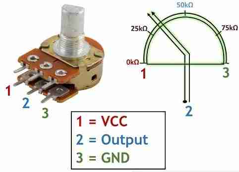
Components are physical elements that are connected in a circuit to perform a specific function, such as controlling current or voltage (resistors), storing energy (capacitors), directing or switching signals (diodes and transistors), or converting electrical signals into motion (motors and servomotors). Combined, they allow the construction of systems that process signals, control devices, and perform tasks.
1.6 What are microcontrollers?
A microcontroller is a single-chip "mini-computer" that integrates a processor, memory, and peripherals (GPIO, ADC, PWM, I2C, SPI, UART). It is used to control hardware by reading sensors and driving actuators in devices such as robots, IoT systems, household appliances, and industrial equipment. The assembled unit of any microcontroller is called a development board.
What is a module?
A module is a ready-to-use board or unit that integrates one or more components (for example, a sensor, a regulator, a microcontroller, or a communication chip) along with everything needed for easy connection (pins, protection, passive components). It simplifies assembly and testing, eliminating the need to design the entire circuit from scratch.
Types of development boards for microcontrollers.
ESP-32
The ESP32 is a family of microcontrollers from Espressif designed for IoT projects and embedded control, notable for integrating Wi-Fi and Bluetooth on the same chip. Typical features include a 32-bit CPU (depending on the model), a generous number of GPIO pins, peripherals such as ADCs, DACs (in some models), PWM (LEDC), timers, and I2C/SPI/UART buses, as well as low-power modes for battery-powered applications. It is commonly programmed using Arduino, ESP-IDF, or MicroPython.
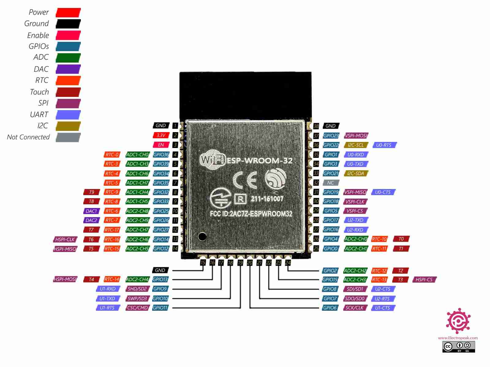
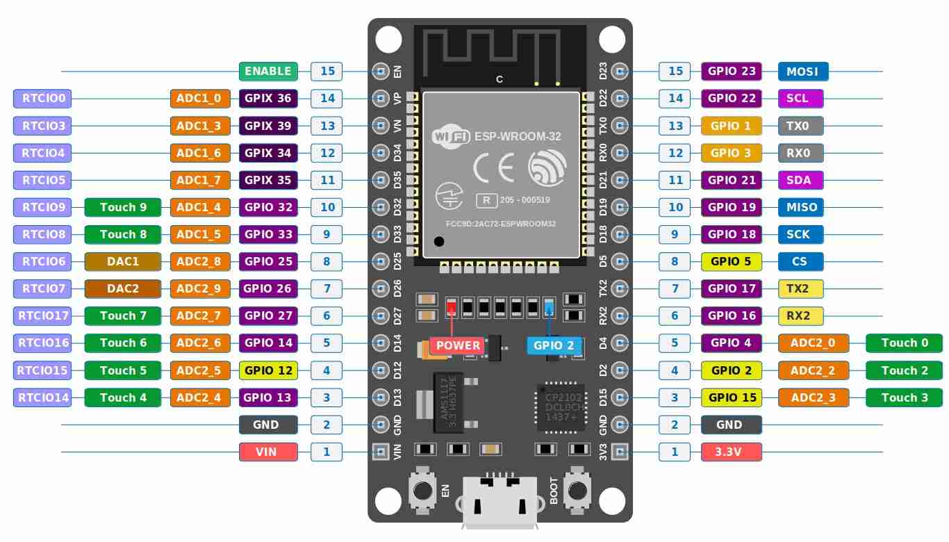
Here is the meaning of each name:
| Pin / Category | Description |
|---|---|
3.3V |
3.3 V power pin (to power 3.3 V sensors/modules). |
Vin 5V |
5 V pin (usually from USB 5 V, or external 5 V feed). |
GND |
Ground / 0 V reference. Common electrical reference. |
EN / RESET |
Enable pin / Reset button. LOW resets the chip; HIGH runs it. |
GPIOxx |
General Purpose Input/Output. General-purpose digital pins. |
ADCx |
Analog-to-Digital Converter. Used to read analog voltages (0–4095). |
DAC1 / DAC2 |
Digital-to-Analog Converter. Generates real analog voltage (GPIO25/26). |
TOUCHx |
Capacitive touch input channels for touch sensing. |
TX / RX |
Transmit / Receive for serial communication (UART). |
SPI (MOSI/MISO/SCK/SS) |
Fast bus pins for communication with SD cards, screens, etc. |
I2C (SDA/SCL) |
2-wire bus for sensors and small displays. |
FLASH Pins |
Internal memory signals. Avoid using these to prevent boot errors. |
Pin numbers (1-38) |
Physical header positions, distinct from internal GPIO numbering. |
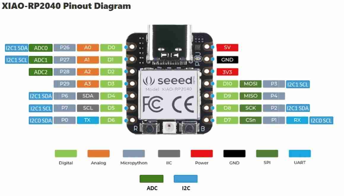
Xiao rp2040
Is a very small development board from Seeed Studio based on the RP2040 microcontroller (the same one used in the Raspberry Pi Pico). It stands out for its compact size, USB-C power supply, good performance for embedded projects, and multiple GPIO pins (with support for I2C/SPI/UART/PWM and analog inputs, depending on the board). It can be programmed with Arduino, MicroPython, or the Pico SDK, and is widely used for prototyping, controls, sensors, and DIY projects where space is limited.
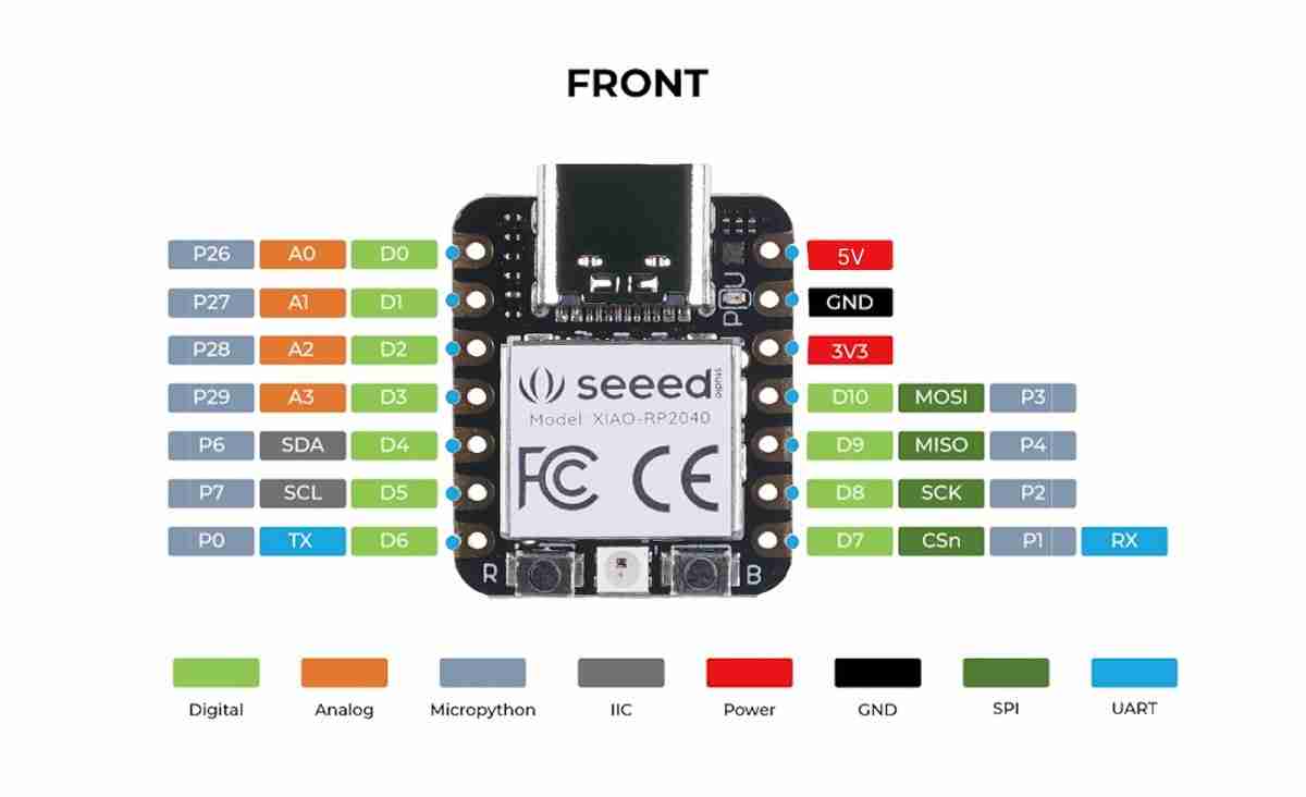
Here is the meaning of each name:
| Pin / Label | Description |
|---|---|
5V |
5-volt power pin (from USB). Powers 5V peripherals (logic is 3.3V). |
3V3 |
Regulated 3.3-volt output for 3.3V sensors and modules. |
GND |
Ground / 0V reference. Must be common with all connected devices. |
D0, D1, D2… |
Digital pin numbers used in Arduino-style examples (Input/Output). |
A0, A1, A2… |
Analog pins for ADC (analogRead). Can also function as digital I/O. |
P0, P1... / GPIO |
Raw RP2040 GPIO numbering used in MicroPython (e.g., GPIO26-29 for ADC). |
SDA / SCL |
I2C Data (SDA) and Clock (SCL) lines. Also known as IIC. |
MOSI / MISO |
Master Out Slave In (Data Out) and Master In Slave Out (Data In). |
SCK / CS |
SPI Clock line and Chip Select (active-low) to activate devices. |
TX / RX |
UART Transmit (Data Out) and Receive (Data In) for serial comms. |
FRONT |
Indicates the component side or orientation of the board. |
XIAO-RP2040 |
Board/Module identification label (Seeed Studio). |
Color Legend |
Visual categories for Digital, Analog, IIC, Power, GND, SPI, and UART functions. |
1.7 What is Wokwi?
Wokwi is an online free simulator for electronics and microcontrollers that allows you to build virtual circuits (with boards like ESP32, Arduino, Raspberry Pi Pico, etc.), connect components (servos, LEDs, sensors, displays), and run your code to test it without real hardware. It's useful for prototyping, learning, debugging connections, and validating logic before building the physical circuit.
2. Simulation in Wokwi
2.1 Search and open wokwi
We will search in internet or click here to open wokwi.
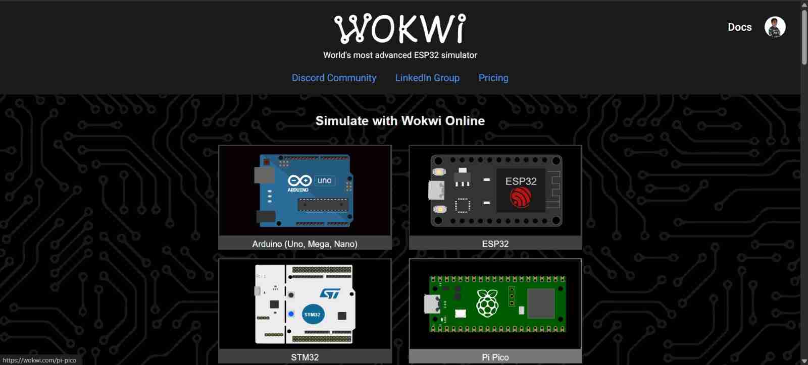
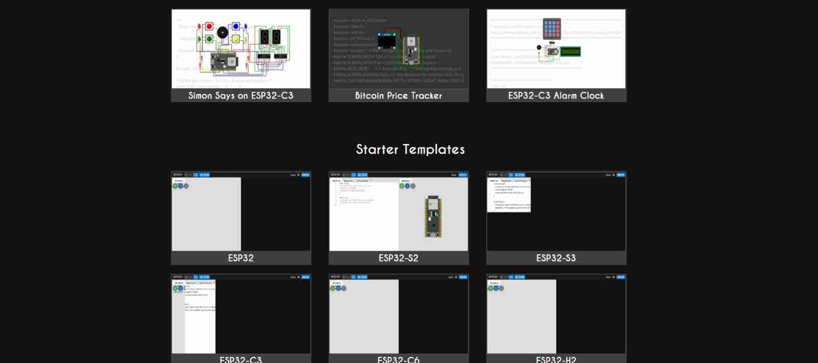
2.2 Open a new project
Once we have chosen the microcontroller we will use, we will have different templates of pre-made projects and new projects; I will select a new one specifically the ESP32.
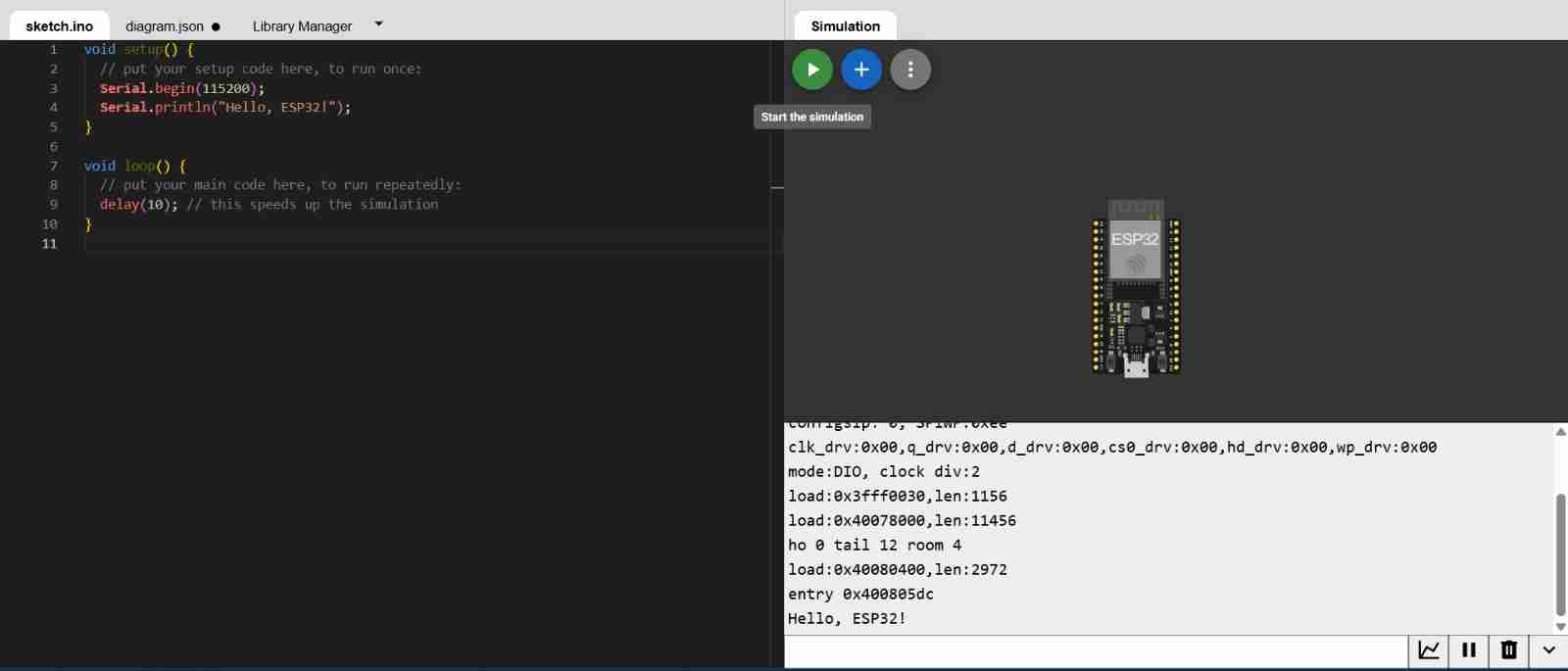
This the view when we open a new project is opened.
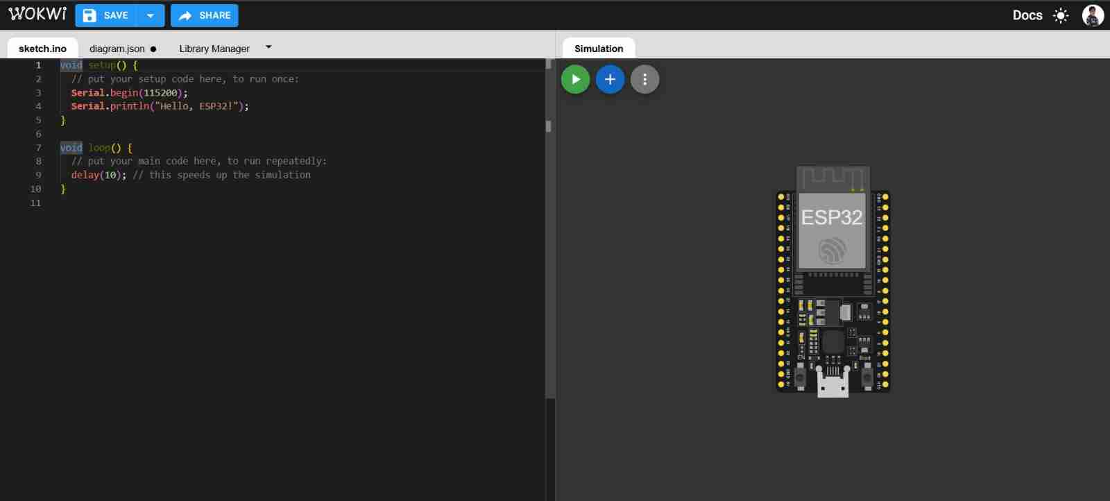
2.3 Test the code
If we click "Start the simulation", the code we have will run; in this case, the code prints "Hello, ESP32!"
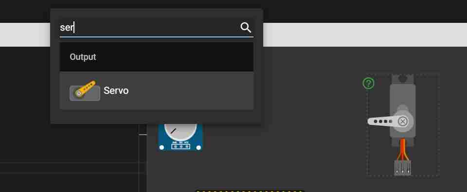
2.4 Add components
The plus icon is a tab for adding components; for example, I will use servomotors, so I will search for their name and click on it to insert the component.
2.5 Adding libraries
Go to "Library Manager" and click on the plus icon; there you will find the library you need.

Clicking will automatically add it and we can use it in our code.
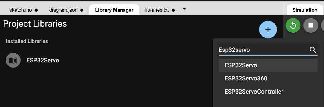
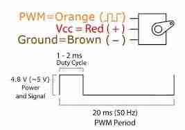
In my case I will add "ESP32servo, which helps in the use of servomotors since these are controlled with a PWM signal "Pulse with modulation", they work at a typical frequency: 50 Hz (one pulse every 20 ms), being that what changes is not the frequency, but the width of the pulse, being the minimum 1000 microseconds at one end, 1500 microseconds in the center and 2000 microseconds at the other end.
Therefore, it correctly configures the ESP32's PWM to 50 Hz, automatically (or manually) assigning an LEDC channel, and converting from degrees or microseconds to actual PWM values. This allows the use of functions such as:
| Command | Function |
|---|---|
servo.attach(pin, minUs, maxUs) |
Connect the servo object to a pin on the ESP32 and configure the minimum and maximum pulse range (in microseconds). Without `attach()`, the servo will not receive a signal. |
servo.write(angulo) |
It sends a position in degrees (usually 0–180). The library internally converts it to a PWM pulse within the range defined in attach(). |
servo.writeMicroseconds(us) |
It directly transmits the pulse width in microseconds (e.g., 1000–2000 µs, or 500–2500 µs). This is more precise and useful for calibration or fine-tuning with sensors/potentiometers. |
servo.detach() |
This "disconnects" the servo from the pin and stops generating the PWM signal. It releases the pin/channel and prevents the servo from continuing to "hold" its position (in many servos it becomes "looser," depending on the model/load). |
2.6 Programing
Using C++ and the library previously added, we are going to programm. The next table explain the basic stuff for the program that I will build.
| Function | Command | Description |
|---|---|---|
| Add libraries | #include <ESP32Servo.h> |
Includes the ESP32Servo library to generate the correct PWM control on the ESP32. |
| Pin definitions | int SERVO_PIN = 18; |
GPIO that outputs the PWM control signal to the servo (signal wire). |
int POT_PIN = 34; |
ADC input pin to read the potentiometer. GPIO34 is input-only on ESP32. | |
| Create object | Servo servo; |
Creates a Servo instance to control the motor via functions like attach() or write(). |
| setup() | Serial.begin(115200); |
Initializes serial communication for debugging at 115200 baud rate. |
servo.setPeriodHertz(50); |
Sets PWM frequency to 50 Hz (20ms period), the standard for hobby servos. | |
servo.attach(SERVO_PIN, 500, 2500); |
Connects servo to pin and defines pulse width range (500µs to 2500µs). | |
| loop() | int adc = analogRead(POT_PIN); |
Reads the potentiometer value from the ADC (returns 0 to 4095). |
int us = map(adc, 0, 4095, 500, 2500); |
Maps the 12-bit ADC reading to the 500-2500µs pulse width range. | |
servo.writeMicroseconds(us); |
Sends the exact pulse width in microseconds to the servo to set its angle. | |
| Serial debug | Serial.print(...); |
Prints the raw ADC value and computed pulse width to the Serial Monitor. |
| Delay | delay(10); |
Waits 10 ms before repeating the loop for stability. |
Here is the full code:
                    #include <ESP32Servo.h>  // ESP32-compatible Servo library (uses hardware PWM via LEDC)

                    // Pin definitions (constants)
                    int SERVO_PIN = 18;   // GPIO used to output the PWM signal to the servo
                    int POT_PIN   = 34;   // ADC-capable GPIO used to read the potentiometer (input only on ESP32)

                    // Create a Servo object instance
                    Servo servo;

                    void setup() {
                    // Initialize Serial for debugging (Serial Monitor)
                    Serial.begin(115200);

                    // Servos typically expect a 50 Hz control signal (20 ms period)
                    servo.setPeriodHertz(50);

                    // Attach the servo to a pin and define pulse width limits in microseconds:
                    // min pulse = 500 us
                    // max pulse = 2500 us
                    servo.attach(SERVO_PIN, 500, 2500);
                    }

                    void loop() {
                    // Read the potentiometer using the ESP32 ADC (typically returns 0..4095)
                    int adc = analogRead(POT_PIN);

                    // Map ADC range (0..4095) to servo pulse width range (500..2500 microseconds)
                    // This converts knob position to a pulse width that represents the servo position.
                    int us = map(adc, 0, 4095, 500, 2500);

                    // Send the pulse width to the servo (more precise than servo.write(angle))
                    servo.writeMicroseconds(us);

                    // Debug output: print raw ADC value and computed pulse width
                    Serial.print("ADC: ");
                    Serial.print(adc);
                    Serial.print("  us: ");
                    Serial.println(us);

                    // Small delay to limit update rate and reduce Serial spam
                    delay(10);
                    }
2.7 Connect diagram
To connect cables, simply click on the pin and input/output; they will connect automatically.
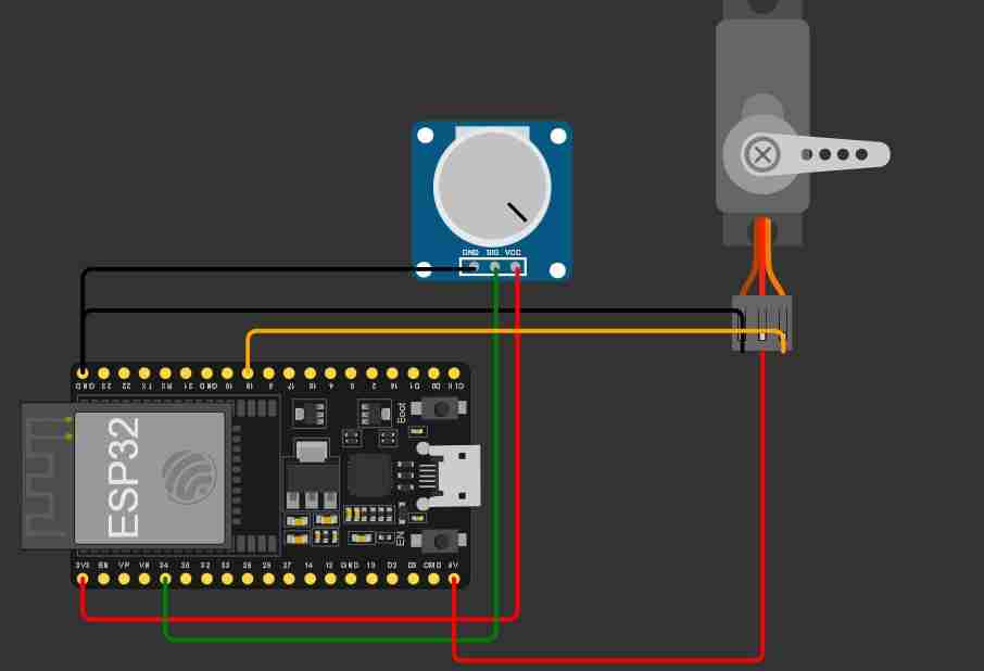
2.8 Test the code and connections
Here is a the view of my first project with all the necessary stuff
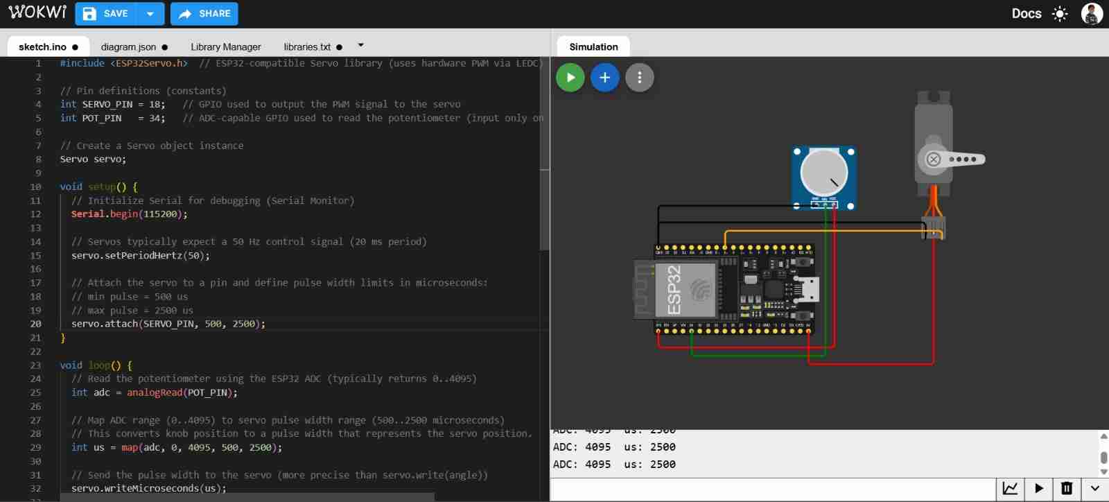
To run the project we will click on the play button and wait to have no errors.
3. Upgrading the project
Since my spiderbot will have 3 servomotors per leg, I will add 2 potentiometers and 2 servomotors using the same logic as the previous code and connections.
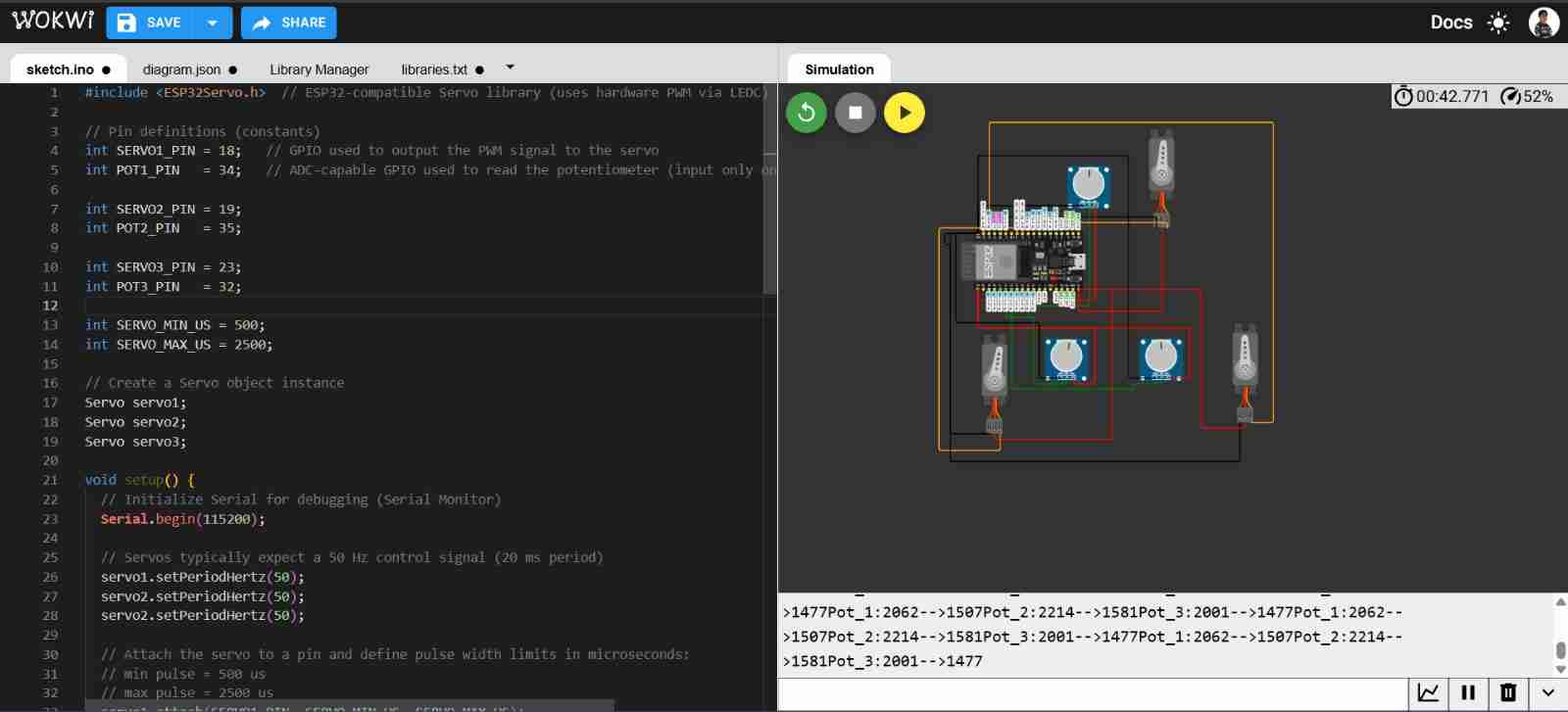
Making the upgrades and testing the project
Here is the code:
                    #include <ESP32Servo.h>  // ESP32-compatible Servo library (uses hardware PWM via LEDC)
                    // Pin definitions (constants)
                    int SERVO1_PIN = 18;   // GPIO used to output the PWM signal to the servo
                    int POT1_PIN   = 34;   // ADC-capable GPIO used to read the potentiometer (input only on ESP32)

                    int SERVO2_PIN = 19;
                    int POT2_PIN   = 35;

                    int SERVO3_PIN = 23;
                    int POT3_PIN   = 32;

                    int SERVO_MIN_US = 500;
                    int SERVO_MAX_US = 2500;

                    // Create a Servo object instance
                    Servo servo1;
                    Servo servo2;
                    Servo servo3;

                    void setup() {
                    // Initialize Serial for debugging (Serial Monitor)
                    Serial.begin(115200);

                    // Servos typically expect a 50 Hz control signal (20 ms period)
                    servo1.setPeriodHertz(50);
                    servo2.setPeriodHertz(50);
                    servo2.setPeriodHertz(50);

                    // Attach the servo to a pin and define pulse width limits in microseconds:
                    // min pulse = 500 us
                    // max pulse = 2500 us
                    servo1.attach(SERVO1_PIN, SERVO_MIN_US, SERVO_MAX_US);
                    servo2.attach(SERVO2_PIN, SERVO_MIN_US, SERVO_MAX_US);
                    servo3.attach(SERVO3_PIN, SERVO_MIN_US, SERVO_MAX_US);
                    }

                    void loop() {
                    // Read the potentiometer using the ESP32 ADC (typically returns 0..4095)
                    int adc1 = analogRead(POT1_PIN);
                    int adc2 = analogRead(POT2_PIN);
                    int adc3 = analogRead(POT3_PIN);


                    // Map ADC range (0..4095) to servo pulse width range (500..2500 microseconds)
                    // This converts knob position to a pulse width that represents the servo position.
                    int us1 = map(adc1, 0, 4095, SERVO_MIN_US, SERVO_MAX_US);
                    int us2 = map(adc2, 0, 4095, SERVO_MIN_US, SERVO_MAX_US);
                    int us3 = map(adc3, 0, 4095, SERVO_MIN_US, SERVO_MAX_US);


                    // Send the pulse width to the servo (more precise than servo.write(angle))
                    servo1.writeMicroseconds(us1);
                    servo2.writeMicroseconds(us2);
                    servo3.writeMicroseconds(us3);

                    // Debug output: print raw ADC value and computed pulse width
                    Serial.print("Pot_1:");Serial.print(adc1);Serial.print("-->");Serial.print(us1);
                    Serial.print("Pot_2:");Serial.print(adc2);Serial.print("-->");Serial.print(us2);
                    Serial.print("Pot_3:");Serial.print(adc3);Serial.print("-->");Serial.print(us3);

                    // Small delay to limit update rate and reduce Serial spam
                    delay(10);
                    }
4. Extra language python
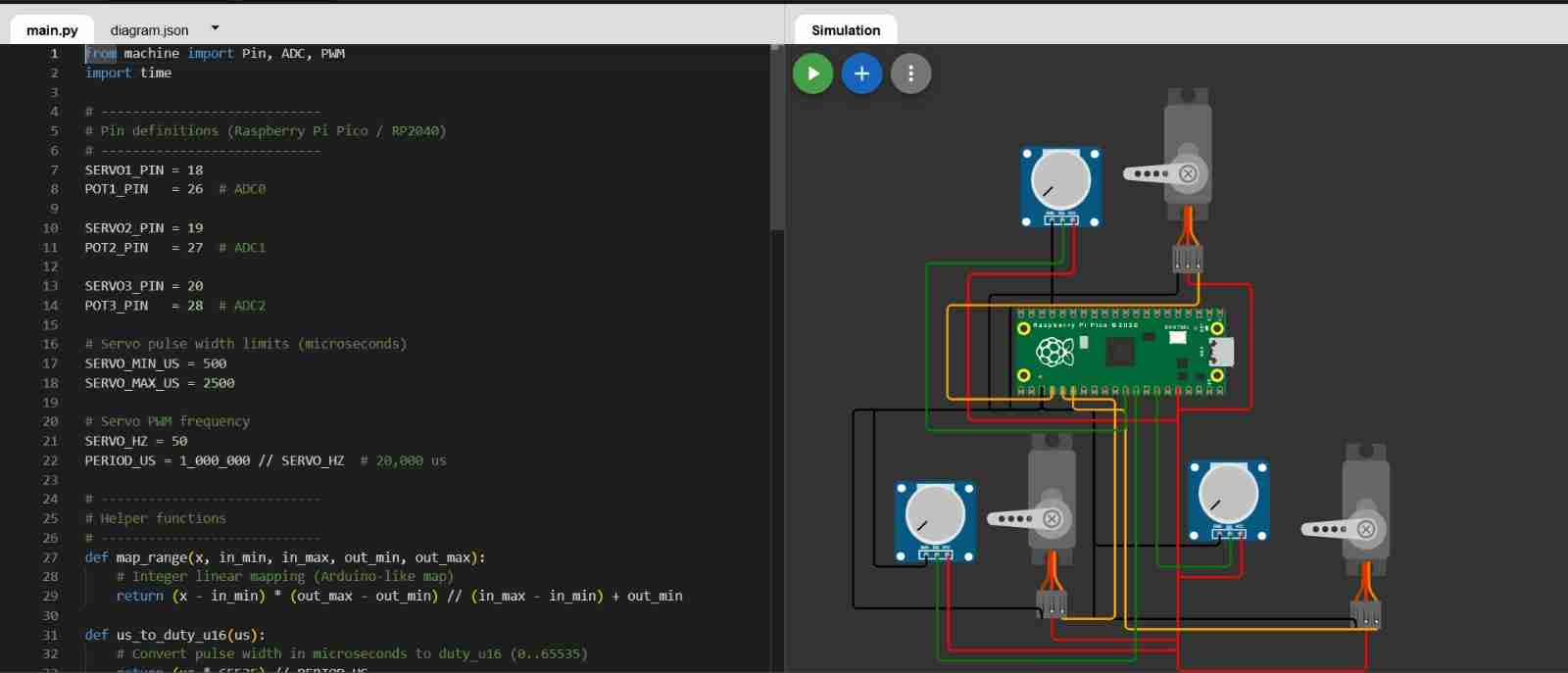
For this I will follow the same process, the only and mainn difference is the language wich now will be python, using MicroPython.
4.1 What is MicroPython?
It is a lightweight Python implementation designed to run on microcontrollers (such as the RP2040, E SP32, and STM32). It allows you to program hardware using Python syntax and modules like machine to control pins, ADCs, PWM, I2C, SPI, and UARTs, with an interpreter optimized for limited resources (memory and CPU).
4.2 Making the new file
We will create a new project in Wokwi but now we will select Pi Pico and then select MicroPython. After we will have to assemble and programm the project, so that finally we can test it. For this one we won't need to add any library.
4.3 Code and explanation
The next information is abour programming in python language.
| Function | Command | Description |
|---|---|---|
| Imports | from machine import Pin, ADC, PWM |
Imports classes to control GPIOs (Pin), read potentiometers (ADC), generate servo signals (PWM), and handle delays (time). |
| Pin definitions | SERVO1_PIN = 18 |
Defines GPIO 18 for PWM output and GP26 (ADC0) for analog input. Pico ADC pins are GP26, GP27, and GP28. |
| Servo pulse limits | SERVO_MIN_US = 500 |
Defines the pulse width range in microseconds: ~500 µs for one end of travel and ~2500 µs for the other. |
| Frequency & Period | SERVO_HZ = 50 |
Standard 50 Hz frequency for servos. PERIOD_US (20,000 µs) is the total cycle length used to calculate PWM duty. |
| Mapping Function | map_range(x, in_min, ..., out_max) |
Linear mapping to convert ADC readings (0-65535) into servo pulse widths (500-2500 µs). |
| Duty conversion | us_to_duty_u16(us) |
Converts microseconds to a 16-bit duty value (0-65535) using the formula: $(us / period) * 65535$. |
| ADC setup | pot1 = ADC(POT1_PIN) |
Creates ADC objects to read the analog voltage from each potentiometer. |
| PWM setup | servo1 = PWM(Pin(SERVO1_PIN)) |
Initializes PWM on servo pins and sets the frequency to 50 Hz. |
| Read ADC | adc1 = pot1.read_u16() |
Reads the potentiometer position as a 16-bit value (0 to 65535). |
| Map values | us1 = map_range(adc1, ..., SERVO_MAX_US) |
Translates the knob's 16-bit position into the specific pulse width required by the servo. |
| Update PWM | servo1.duty_u16(us_to_duty_u16(us1)) |
Applies the calculated duty cycle to the PWM pin to move the servo. |
| Debug & Stability | print(...) |
Prints values for verification and adds a 10 ms pause to keep the system stable. |
Complete code:
from machine import Pin, ADC, PWM
import time
# ----------------------------
# Pin definitions (Raspberry Pi Pico / RP2040)
# ----------------------------
SERVO1_PIN = 18
POT1_PIN = 26 # ADC0
SERVO2_PIN = 19
POT2_PIN = 27 # ADC1
SERVO3_PIN = 20
POT3_PIN = 28 # ADC2
# Servo pulse width limits (microseconds)
SERVO_MIN_US = 500
SERVO_MAX_US = 2500
# Servo PWM frequency
SERVO_HZ = 50
PERIOD_US = 1_000_000 // SERVO_HZ # 20,000 us
# ----------------------------
# Helper functions
# ----------------------------
def map_range(x, in_min, in_max, out_min, out_max):
# Integer linear mapping (Arduino-like map)
return (x - in_min) * (out_max - out_min) // (in_max - in_min) + out_min
def us_to_duty_u16(us):
# Convert pulse width in microseconds to duty_u16 (0..65535)
return (us * 65535) // PERIOD_US
# ----------------------------
# ADC setup
# ----------------------------
pot1 = ADC(POT1_PIN)
pot2 = ADC(POT2_PIN)
pot3 = ADC(POT3_PIN)
# ----------------------------
# PWM setup for servos
# ----------------------------
servo1 = PWM(Pin(SERVO1_PIN))
servo2 = PWM(Pin(SERVO2_PIN))
servo3 = PWM(Pin(SERVO3_PIN))
servo1.freq(SERVO_HZ)
servo2.freq(SERVO_HZ)
servo3.freq(SERVO_HZ)
# ----------------------------
# Main loop
# ----------------------------
while True:
# RP2040 ADC gives 0..65535
adc1 = pot1.read_u16()
adc2 = pot2.read_u16()
adc3 = pot3.read_u16()
# Map ADC (0..65535) to servo pulse width (us)
us1 = map_range(adc1, 0, 65535, SERVO_MIN_US, SERVO_MAX_US)
us2 = map_range(adc2, 0, 65535, SERVO_MIN_US, SERVO_MAX_US)
us3 = map_range(adc3, 0, 65535, SERVO_MIN_US, SERVO_MAX_US)
# Write PWM duty corresponding to pulse width
servo1.duty_u16(us_to_duty_u16(us1))
servo2.duty_u16(us_to_duty_u16(us2))
servo3.duty_u16(us_to_duty_u16(us3))
# Debug
print("Pot_1:", adc1, "-->", us1,
"| Pot_2:", adc2, "-->", us2,
"| Pot_3:", adc3, "-->", us3)
time.sleep_ms(10)
5. Making the projects in physical
For this I will use a breadboard this makes it easier for me to connect, because in the program the connections were either unreliable or floating.
5.1 Physical connection using ESP32
For this one I used Arduino IDE software which is free and it that allows you to program Arduino boards using a C/C++-based programming language.
5.2 Using Arduino IDE
Download it from the previous link.
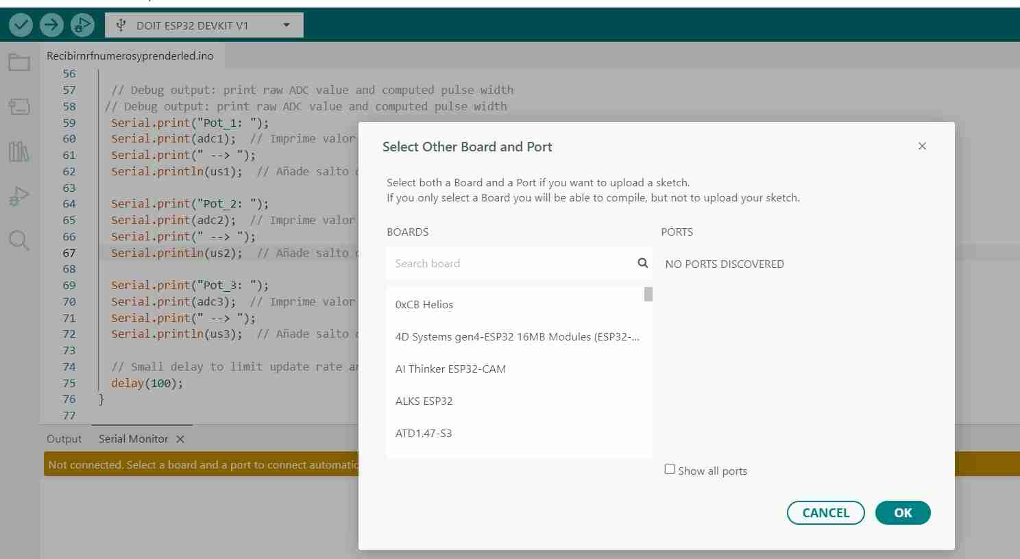
5.2.2 Select the board that you are going to work
You are going to connect your ESP32 to your computer through a USB cable, then click the usb logo which should appear like COM # that are the ports of your computer, then wou will search for the board you are going to use. My case I chose DOIT ESP32 DEVKIT V1 which is the default ESP32 board and also the one that is most commonly used.
5.2.3 Running the code
I copy and paste almost all of my code (I only modified the part about printing the potentiometer and servo values so they are easier to see) and connect it exactly as declared in the code.
Here is the code with change on the print information.
                    #include <ESP32Servo.h>  // ESP32-compatible Servo library (uses hardware PWM via LEDC)

                    // Pin definitions (constants)
                    int SERVO1_PIN = 18;   // GPIO used to output the PWM signal to the servo
                    int POT1_PIN   = 34;   // ADC-capable GPIO used to read the potentiometer (input only on ESP32)

                    int SERVO2_PIN = 19;
                    int POT2_PIN   = 35;

                    int SERVO3_PIN = 23;
                    int POT3_PIN   = 32;

                    int SERVO_MIN_US = 500;
                    int SERVO_MAX_US = 2500;

                    // Create a Servo object instance
                    Servo servo1;
                    Servo servo2;
                    Servo servo3;

                    void setup() {
                    // Initialize Serial for debugging (Serial Monitor)
                    Serial.begin(115200);

                    // Servos typically expect a 50 Hz control signal (20 ms period)
                    servo1.setPeriodHertz(50);
                    servo2.setPeriodHertz(50);
                    servo2.setPeriodHertz(50);

                    // Attach the servo to a pin and define pulse width limits in microseconds:
                    // min pulse = 500 us
                    // max pulse = 2500 us
                    servo1.attach(SERVO1_PIN, SERVO_MIN_US, SERVO_MAX_US);
                    servo2.attach(SERVO2_PIN, SERVO_MIN_US, SERVO_MAX_US);
                    servo3.attach(SERVO3_PIN, SERVO_MIN_US, SERVO_MAX_US);
                    }

                    void loop() {
                    // Read the potentiometer using the ESP32 ADC (typically returns 0..4095)
                    int adc1 = analogRead(POT1_PIN);
                    int adc2 = analogRead(POT2_PIN);
                    int adc3 = analogRead(POT3_PIN);


                    // Map ADC range (0..4095) to servo pulse width range (500..2500 microseconds)
                    // This converts knob position to a pulse width that represents the servo position.
                    int us1 = map(adc1, 0, 4095, SERVO_MIN_US, SERVO_MAX_US);
                    int us2 = map(adc2, 0, 4095, SERVO_MIN_US, SERVO_MAX_US);
                    int us3 = map(adc3, 0, 4095, SERVO_MIN_US, SERVO_MAX_US);


                    // Send the pulse width to the servo (more precise than servo.write(angle))
                    servo1.writeMicroseconds(us1);
                    servo2.writeMicroseconds(us2);
                    servo3.writeMicroseconds(us3);

                    // Debug output: print raw ADC value and computed pulse width
                    // Debug output: print raw ADC value and computed pulse width
                    Serial.print("Pot_1: ");
                    Serial.print(adc1);  // Prints POT1
                    Serial.print(" --> ");
                    Serial.println(us1);  // Add new line

                    Serial.print("Pot_2: ");
                    Serial.print(adc2);  // Prints POT2
                    Serial.print(" --> ");
                    Serial.println(us2);

                    Serial.print("Pot_3: ");
                    Serial.print(adc3);  // Prints POT3
                    Serial.print(" --> ");
                    Serial.println(us3);
                    // Small delay to limit update rate and reduce Serial spam
                    delay(100);
                    }
5.3 Physical connection using Xiao rp2040
For this one I used Thonny IDE is an integrated development environment (IDE) designed to make programming in Python easier, especially for beginners.
5.3.1 Download and open Thony
Download it from the previous link.
5.2.2 Select the board that you are going to work
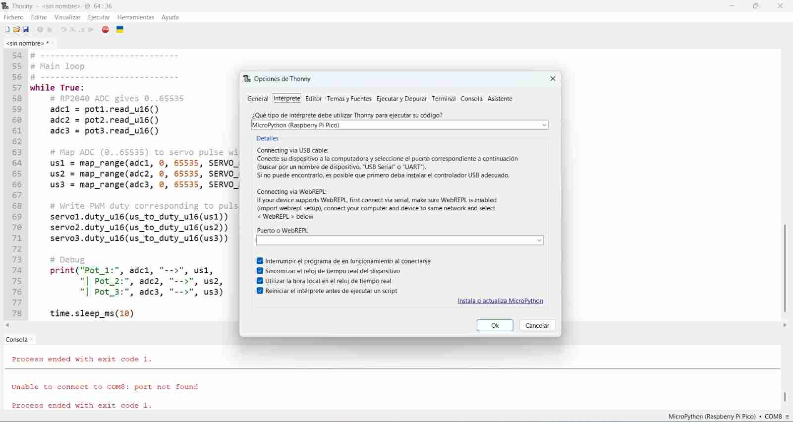
Tools section in the top of the screen, selected the options and then I opened the interpreter menu and selected the MicroPython (Raspberry PiPico) interpretrer.
5.2.3 Installing Micropython
For coding I will use Micropython, to install it on the Xiao you will have to connect the Xiao with a cable to your computer.
To do this, go to Tools, Options and click on "Install or update Micropython", Another tab will open. In "Micropython family" select "RP2. And in "variant" the one that says "RaspberryPi Pico / Pico H"
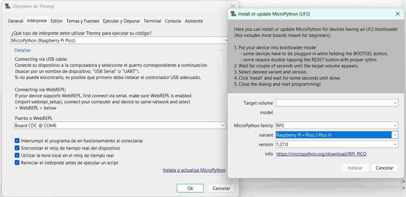
It will be installed on our Xiao and now we can load the code.
5.2.4 Running the code
I copy and paste almost all of my code I modified the used pins becuase on the simulation I had more than on the physical Xiao.
Important reminder
When defining the pins you are going to use beacuse if not your code will not work, if you are using Micropython be sure tu use the grey pins in the pinout of the Xiao rp2040.
Here is the complete code:
                    from machine import Pin, ADC, PWM
                    import time

                    # ----------------------------
                    # Pin definitions (Raspberry Pi Pico / RP2040)
                    # ----------------------------
                    SERVO1_PIN = 6
                    POT1_PIN   = 26  # ADC0

                    SERVO2_PIN = 7
                    POT2_PIN   = 27  # ADC1

                    SERVO3_PIN = 0
                    POT3_PIN   = 28  # ADC2

                    # Servo pulse width limits (microseconds)
                    SERVO_MIN_US = 500
                    SERVO_MAX_US = 2500

                    # Servo PWM frequency
                    SERVO_HZ = 50
                    PERIOD_US = 1_000_000 // SERVO_HZ  # 20,000 us

                    # ----------------------------
                    # Helper functions
                    # ----------------------------
                    def map_range(x, in_min, in_max, out_min, out_max):
                        # Integer linear mapping (Arduino-like map)
                        return (x - in_min) * (out_max - out_min) // (in_max - in_min) + out_min

                    def us_to_duty_u16(us):
                        # Convert pulse width in microseconds to duty_u16 (0..65535)
                        return (us * 65535) // PERIOD_US

                    # ADC setup

                    pot1 = ADC(POT1_PIN)
                    pot2 = ADC(POT2_PIN)
                    pot3 = ADC(POT3_PIN)

                    # PWM setup for servos

                    servo1 = PWM(Pin(SERVO1_PIN))
                    servo2 = PWM(Pin(SERVO2_PIN))
                    servo3 = PWM(Pin(SERVO3_PIN))

                    servo1.freq(SERVO_HZ)
                    servo2.freq(SERVO_HZ)
                    servo3.freq(SERVO_HZ)

                    # Main loop

                    while True:
                        # RP2040 ADC gives 0..65535
                        adc1 = pot1.read_u16()
                        adc2 = pot2.read_u16()
                        adc3 = pot3.read_u16()

                        # Map ADC (0..65535) to servo pulse width (us)
                        us1 = map_range(adc1, 0, 65535, SERVO_MIN_US, SERVO_MAX_US)
                        us2 = map_range(adc2, 0, 65535, SERVO_MIN_US, SERVO_MAX_US)
                        us3 = map_range(adc3, 0, 65535, SERVO_MIN_US, SERVO_MAX_US)

                        # Write PWM duty corresponding to pulse width
                        servo1.duty_u16(us_to_duty_u16(us1))
                        servo2.duty_u16(us_to_duty_u16(us2))
                        servo3.duty_u16(us_to_duty_u16(us3))

                        # Debug
                        print("Pot_1:", adc1, "-->", us1,
                            "| Pot_2:", adc2, "-->", us2,
                            "| Pot_3:", adc3, "-->", us3)

                        time.sleep_ms(10)
How it works:
6. Conclusions
Simulators like wokwi are great if you don't have the components yet to test your projects but as they are simulations they "always work" beacause is the ideal case for components for work, but in real life components dont't always have the ideal behaviour.
Therefore, simulation is a very good tool for testing code, since when moving to physical implementation we can encounter problems because we have to consider real-world conditions such as noise, external sources, etc.
7. Projects created
Here are the links for the projects created in Wokwi: