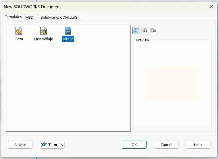
Week 3. Computer-Controlled Cutting
Summary
This week we focused on how to create parametric designs using equations in my case using SolidWorks, then exporting them as dxf format to cut it on the laser cut. After that we learn how to use the vinyl cutter to make stickers.
Group assignment
Here is the group assignment to check more information about the laser cutter rules, safety parameters, etc.
1. Basic concepts
1.1 What are a laser cutter machines?
Laser cutters are machines that use a concentrated beam of light to cut, engrave, or mark materials with high precision. The laser heats the material until it melts, burns, or vaporizes, following a digital design.
1.2 What is parametric design?
Parametric design is a design method where the dimensions and characteristics of a model are defined by parameters (variables). Changing a value automatically updates the entire design without requiring it to be redone.
1.3 What are equations in CAD programs
A tool that allows you to control the dimensions of a model using variables and mathematical formulas, instead of fixed values. Working by: define global variables (e.g., length, width, thickness), relate dimensions to formulas and change a variable, the model updates automatically.
1.4 What are dxf files?
DXF (Drawing Exchange Format) files are vector drawing files used to exchange technical designs between different CAD programs and manufacturing machines. We can obtain this type of files using any 2D software or in 3D softwares we need to use a "drafting" tool to save the dxf, later we'll see how to do this.
1.5 What are svg files?
SVG (Scalable Vector Graphics) files are vector graphics files that describe images using mathematical shapes, not pixels. Therefore, they can be scaled to any size without losing quality. We can obtain this files by using inkscape or any 2D software.
2 Parametric design in SolidWorks
2.1 Design references
For the design of my piece i wanted that my figure can assemble in different ways up to the creativity of the user my main inspirations were the "tazos" that are a mexican toy that used to come in the bags of chips from "Sabritas"or "Lays". There was an edition from Spider-man that let you assemble the tazos in many ways so I used the press-fit joints to do this.
I also wanted it to have different shapes where the number of tabs equaled the number of sides, adapting geometric shapes from a triangle to an octagon or larger. As long as the figure's dimensions allowed it to grow, it would have n sides with n sides. For this design, my professor Oliver helped me to formulate the equations I would use.
2.2 Shape of the figure
For the shape as I wanted to decrease or increase the tabs in order to number of sides I used a traingle wich is the main basic figure that if you repeat ir you can make any figure.
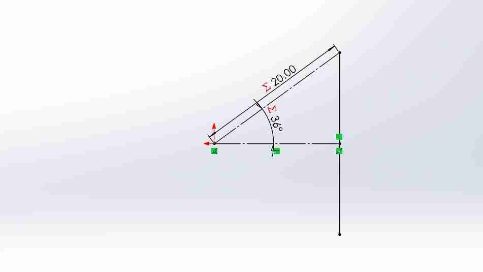
2.2.1 Sketching the triangle
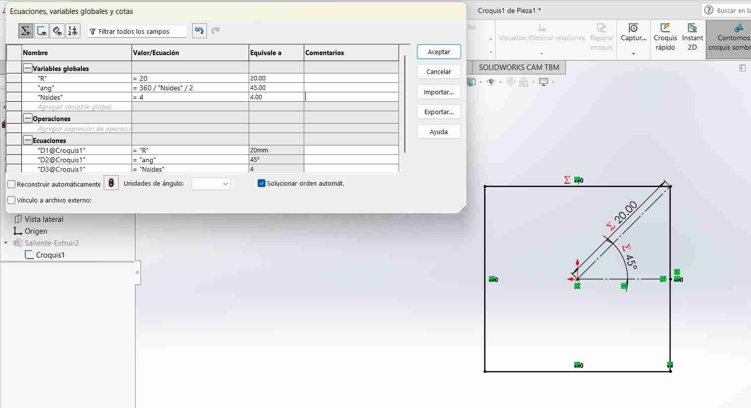
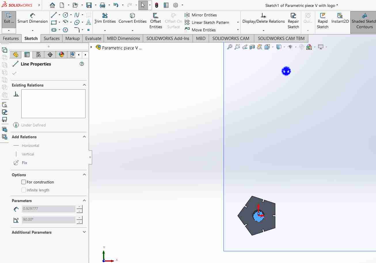
This traingle sketched using 2 reference lines and 1 line, the 2 reference lines were used as the lines of the triangle positioning the vertical line in its midpoint. The length of the dimension will be " R" this will set the lenght of the figure and "ang" will be the angle of the figure, this is the most important dimension since this will modify the triangle shape, the explanation of this formula is 360 internal by polygon rules /Nsides/2 so that it doesn't give the total because our figure goes from one half to the other half
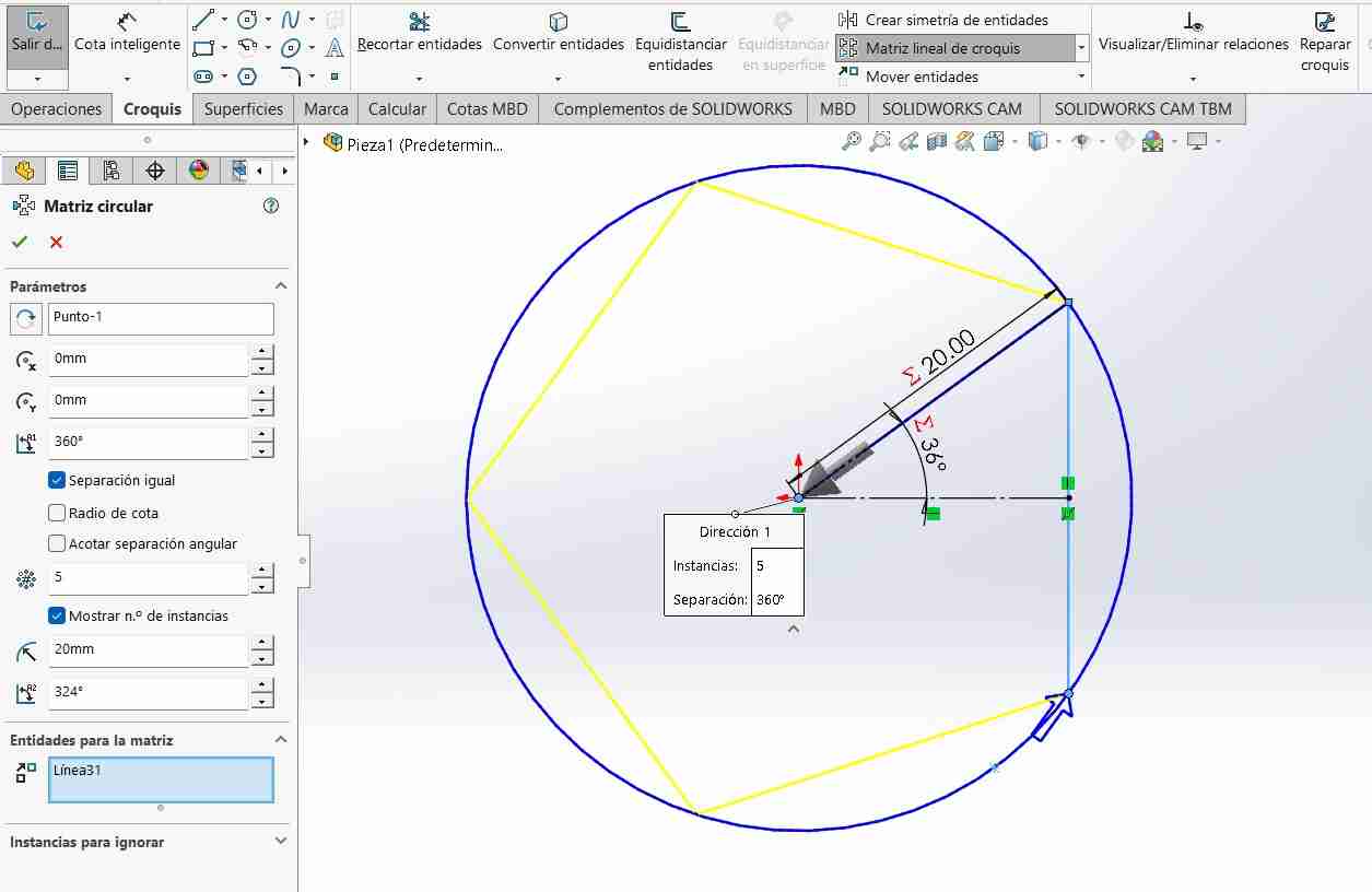
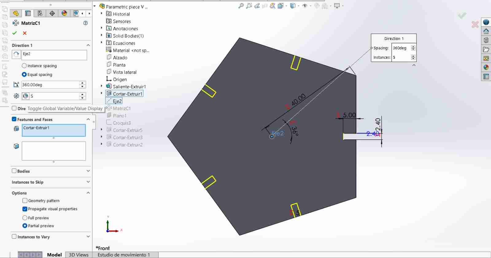
2.2.2 Circular array
To make my vertical line repeat, we use the "Circular Array" tool. Once there, we must select where it will rotate, in my case on axis 1, and how many times or "instances" it will repeat. It is important to activate the "show n instances" option because we will modify it later.
2.2.3 Stablishing equations during the sketch
After that we need to click on the number that appear on the figure to declare it as global equation that represent the nomber of sides "Nsides".
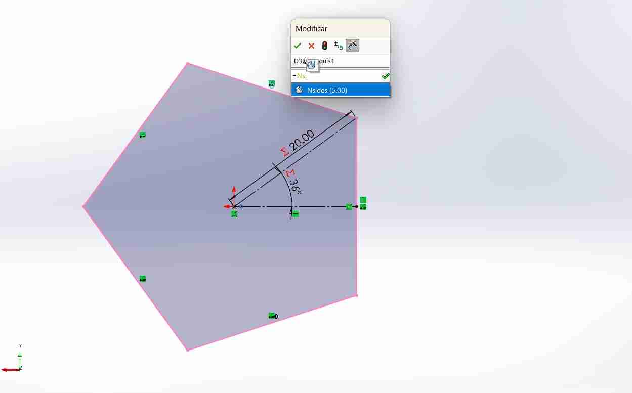
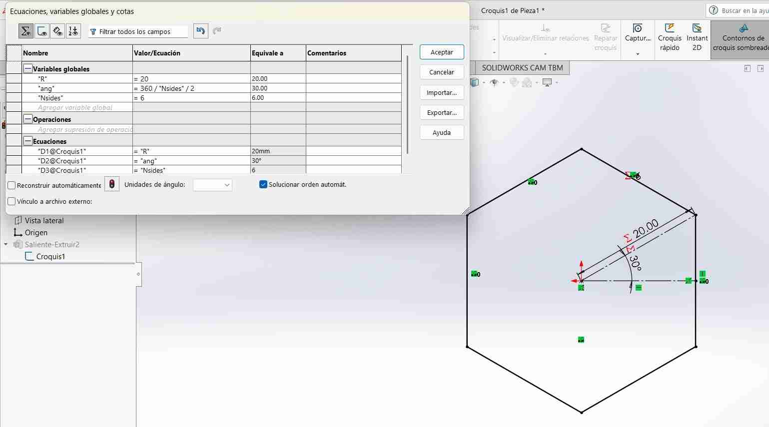
After that we can change the number sides and the figure will change immmediately.
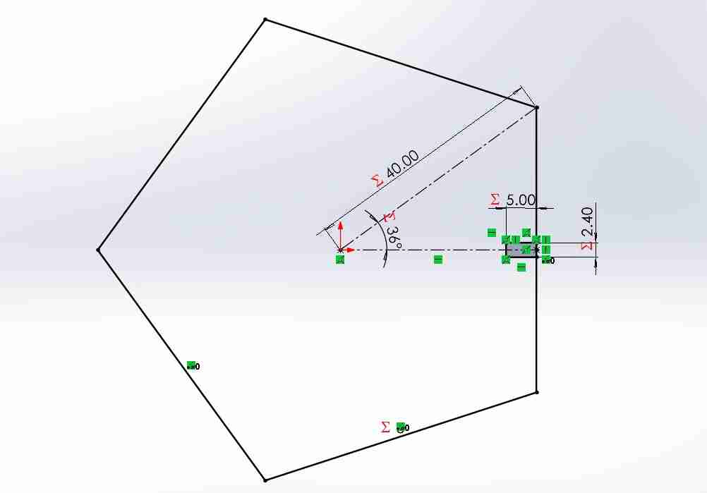
2.2.4 Add the tabs for joints
For the last part we need to add the tabs to create the joints that will link our figures between them. with one of the kerf test I calculated that if I wanted to make press fit joints my tabs should have a thickness of 2.4mm for the MDF material of 2.5mm of thickness.
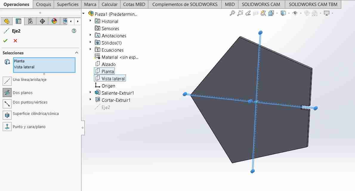
2.2.5 Add an axis
For replicate or create a circular matrix around the figure we need and axis for the sketch to rotate. for that we need to go to reference geometry and select axis after that we select the reference planes and then we add it.
2.2.6 Create a circular array
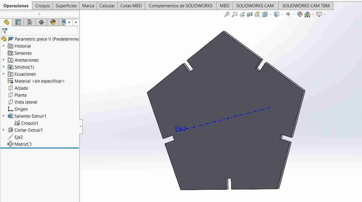
After we add the axis we use the tool circular pattern to create a circular array of our tab, equating the number of sides with the number of tabs
Here is the figure with the circular pattern
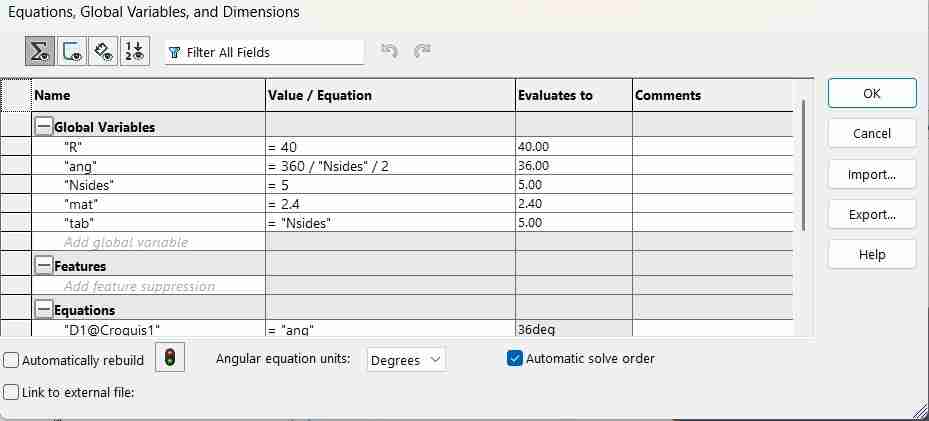
- R = radious of circle
- ang = 360/Nsides/2
- mat = with of your material (not mandatory)
- tab = sides of our figure
2.3 Equations used
To get an authentic parametric figure we can add the thickness of the material, getting in total 4 values/equations
3. Adding images for engrave your piece in SolidWorks
If you want to engrave your piece with the laser cutter you will have to import an image to SolidWorks. For this SolidWorks agilize this process to be simple and efficient using dxf files.
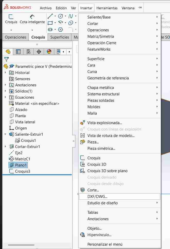
3.1 Add the dxf file
For this you will go to insert and select DXF/DWG...
3.2 Import your dxf file
Afetr you click on the tab you will have to select your file and then open it. Then a tab will pop up you will click on next without making any changes.
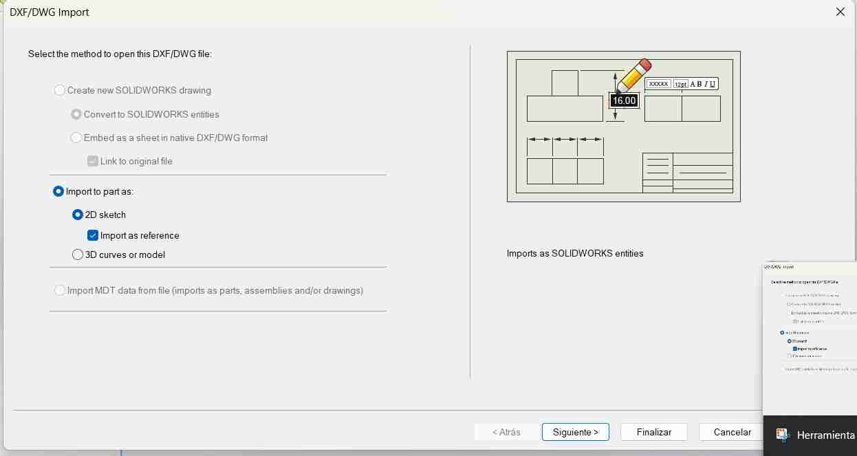
The you will click on next and then finish.
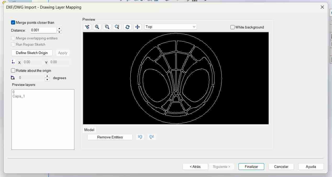
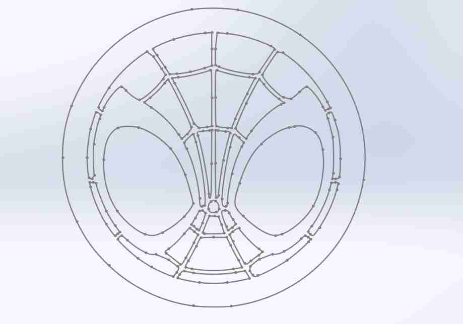
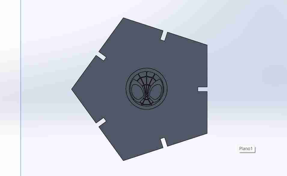
After it will appear then the vectorized image on the plane we select.
If the image doesnt show on the place you need it to be you can move it by right clicking on it and select make edit skecth.
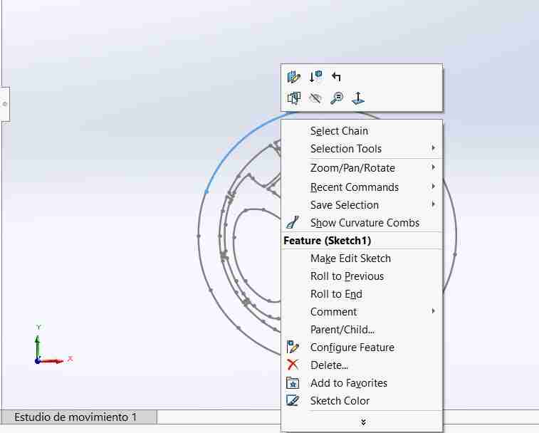
Then you sould open the sketch in that way you can move the image.
3.3 Engraving the piece
For this final step you just need to cut the sketch the minimum, just so that wen we export it on the draft tool to convert ir to dxf the image shows up.
4. Convert our model to a dxf file
4.1 Open the draft tool
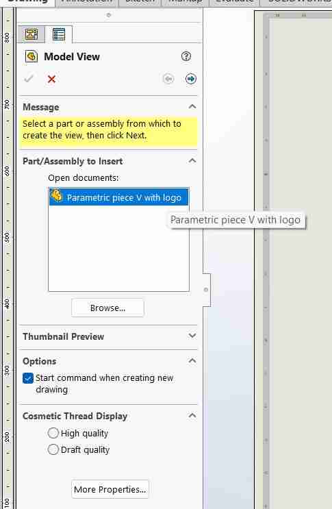
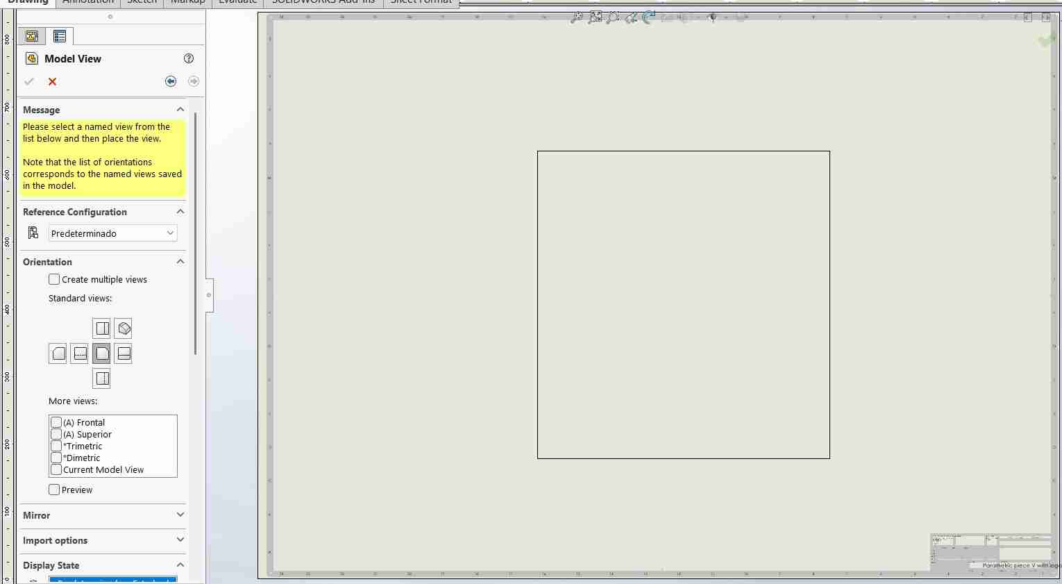
To save our model as dxf we need to open the tool called Drafting (this tool allows to turn your 3D model into a plane and add measures or in our case to save files as dxf),
4.2 Insert the model
A tab will appear in the left side of the screen showing the next options, we will onle dooble click on the name of the file we just saved.
After you double clicked it you can place it were ever you want, then you can click esc because we don't need the other views.
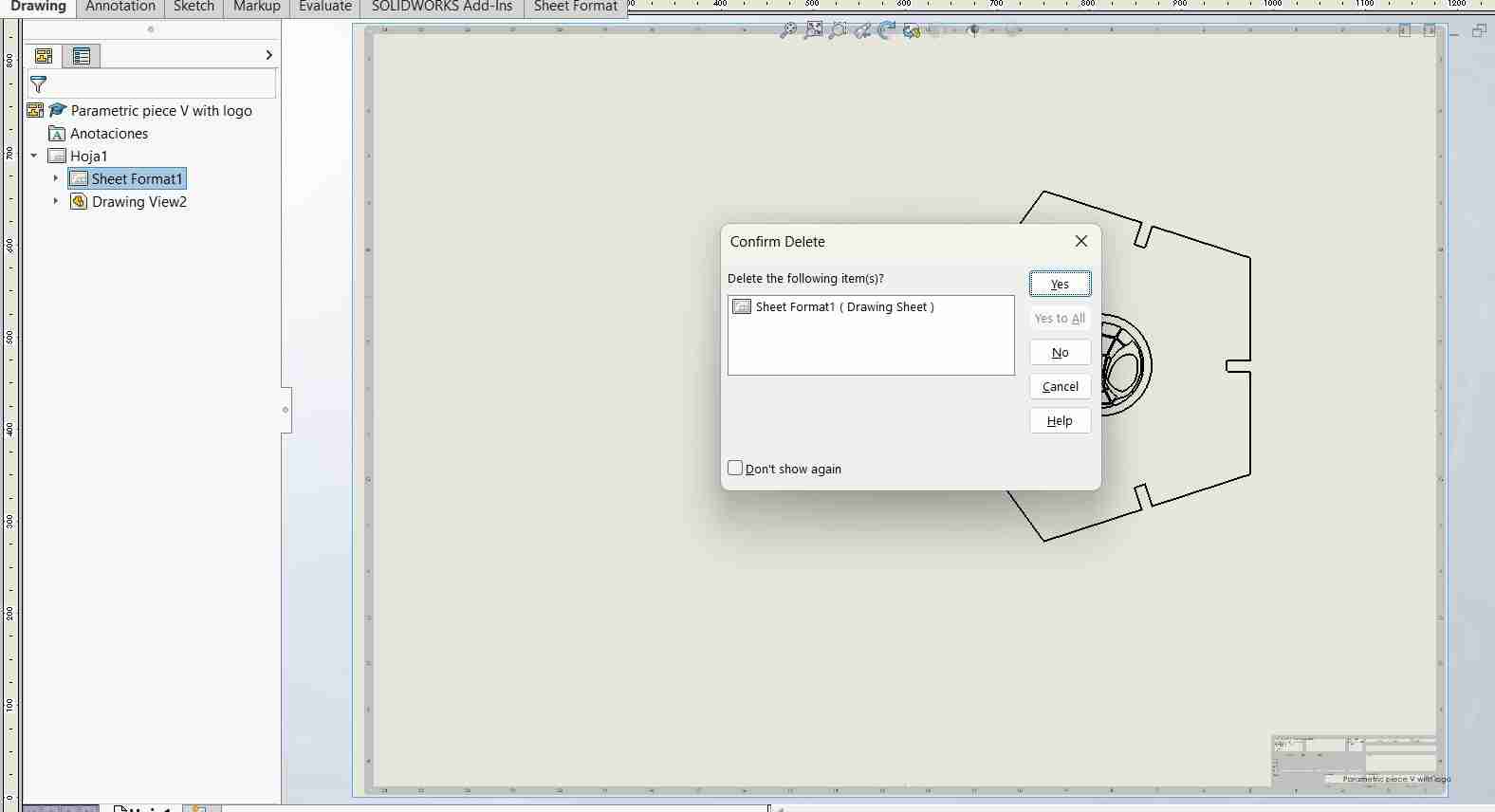
4.3 Delete the borders
It's important to erase the border of our sheet, otherwise it will appear in our dxf file.
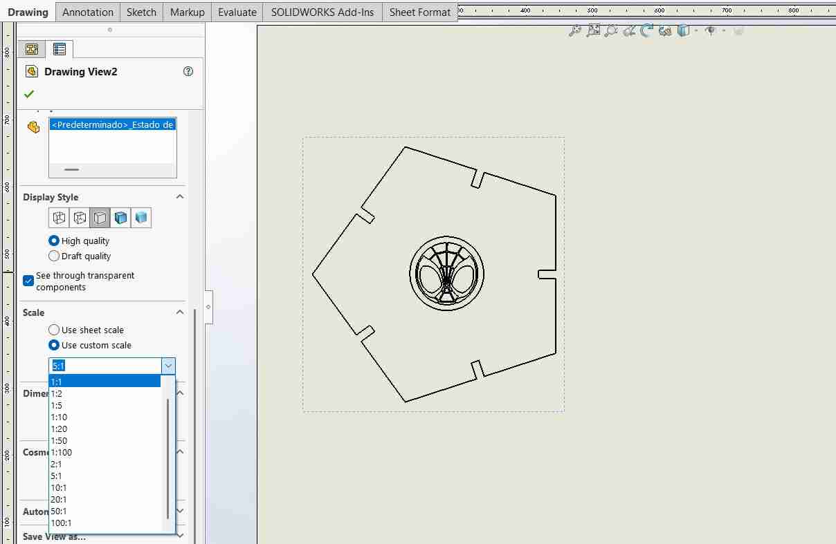
4.4 Scale your draft
It is important to select the scale of our figure because otherwise it will be smaller or larger; we will select 1:1
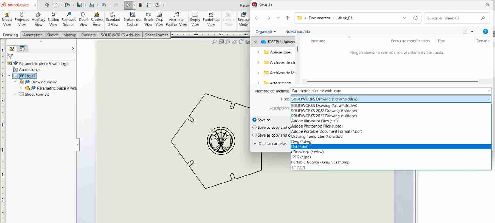
4.5 Save the document as dxf
To save our file, we'll go to save, save as, and select dxf.
4. Living hinges
4.1 What is a living hinge?
Is a thin, flexible hinge created from the same material as the two rigid pieces it connects, allowing them to pivot relative to each other. In laser cutting, a living hinge is made by making a series of closely-spaced cuts into a material, typically wood or acrylic, which allows it to bend along the line of cuts Living hinges are widely used in product design for applications such as lids on packaging, flexible joints in toys, and movable parts in furniture, providing a combination of utility and elegant design simplicity.
4.2 Design inspiration
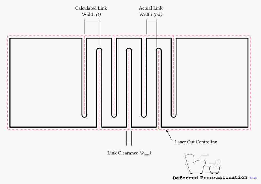
Deffered Procrastination calculated on his web page a way to get a parametric design of a living hinge. This is done by getting the minimum Torsional Links the thickness of the material the laser Kerf, the maximum torsional stress allowed and the minimum lenght of link. You can see the following image they provided for a visual clarification of the different part of the living hinge.
4.3 Living hinge design and equations
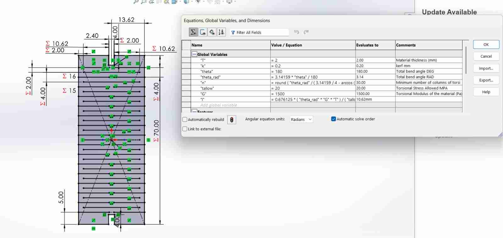
The next image is the main deisgn for create a living hinge.
Here are the equations that defines the motion and characteristics of a living hinge.
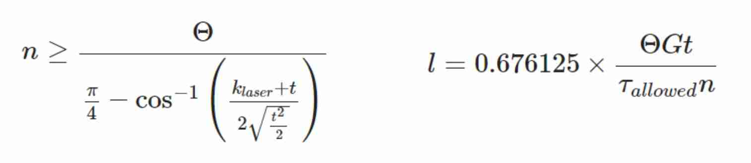
- Θ = Total bend angle of the piece (Θ=θ×n)
- klaser = Laser Kerf (m)
- l = Torsional link length (m)
- n = Number of columns of torsional links
- t = Material thickness (m)
- G = Torsional Modulus of the material (Pa)
- τ = Torsional Stress (Pa)
4.4 Living hinge in SolidWorks
After we read the information we can sketch and import our file with the previous steps.
5. Smartcarve
5.1 What is Smartcarve?
SmartCarve is a control program for laser cutters and CNC routers. It acts as an intermediary between your design (DXF, SVG, etc.) and the machine, allowing you to configure cutting/engraving parameters (power, speed, passes) and send jobs directly to the machine. It is licensed or tied to a specific user/machine, so it needs administrator permissions to communicate with the laser controller.
5.2 Using Smartcarve
5.2.1 Get the key acces
In my case, I must have to have the USB to work on the programm.
5.2.2 Import the dxf file
Once we can acces we will import our dfx file going to file, export and select the document or documents.
5.2.3 Put a different color
Changing color is helpfull if we eant to declare if a color will cut or engrave. For that we select the line or object and the right click on Apply to.
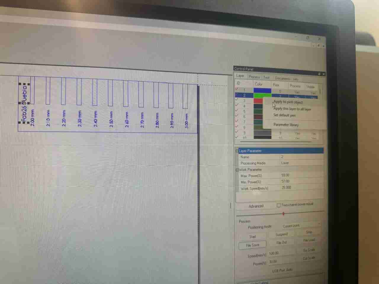
After we clicked we just need to set the parameters configuration.
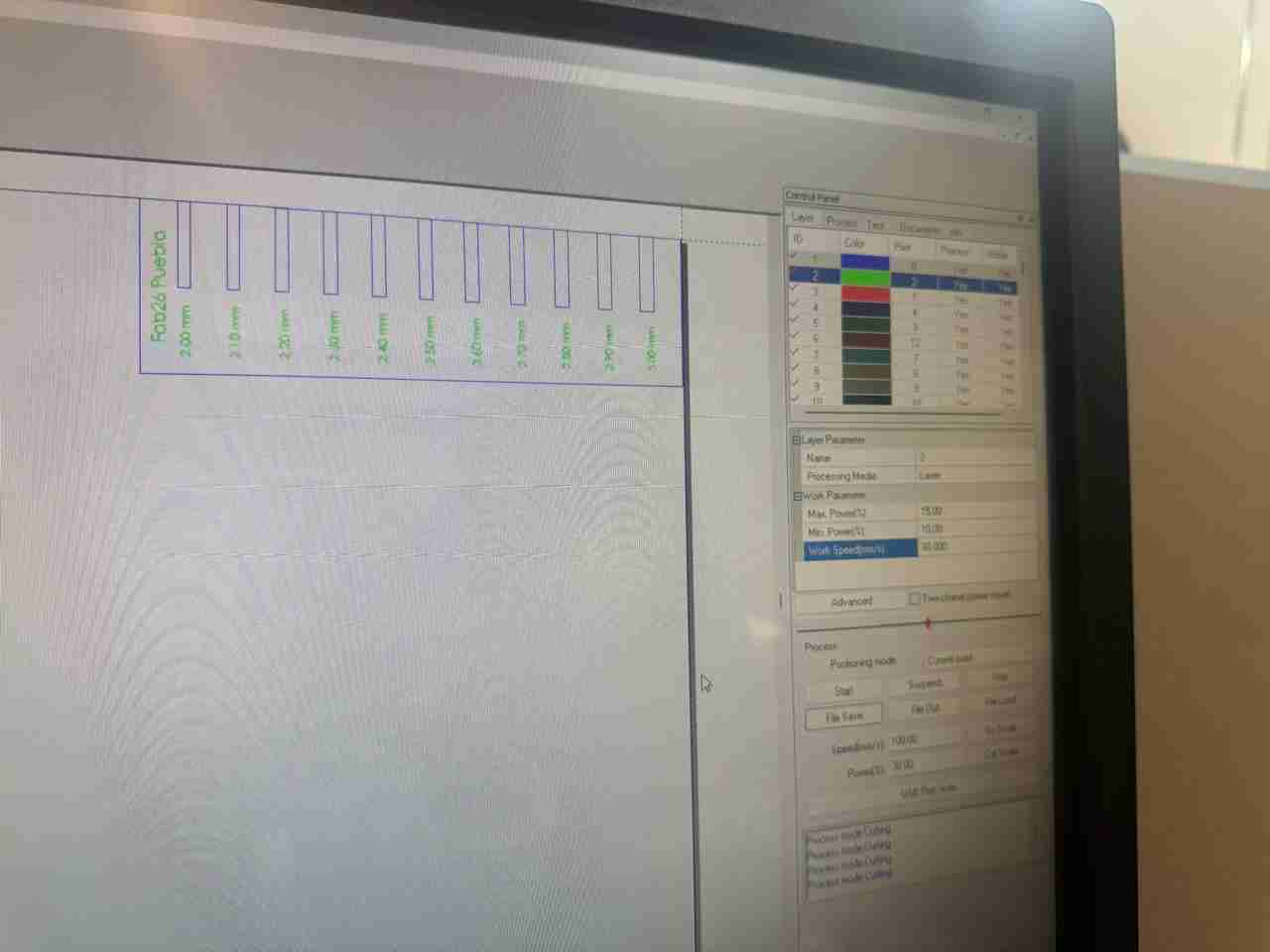
This is the configuration for engarving part.
- Power max: 15%
- Power min: 10%
- speed: 120 mm/s
This is the configuration for cutting.
- Power max: 55%
- Power min: 50%
- speed: 40 mm/s
5.2.4 Use of arrays
Convert arrays is a tool that copy/paste the figure the number you wanted, it works on generating the muber of rows and columns the user wants.
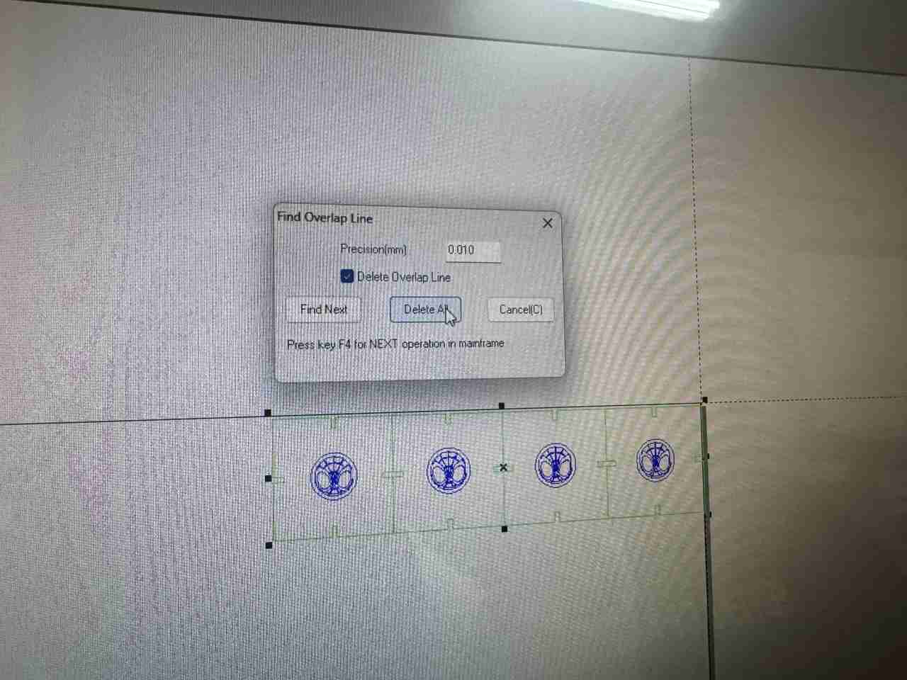
5.2.3 Use overlap tool
This tool allows you to make sure the laser cutter don't pass twice in a line that is shared by 2 or more figures. We will right click on the object and select Find overlap lines .
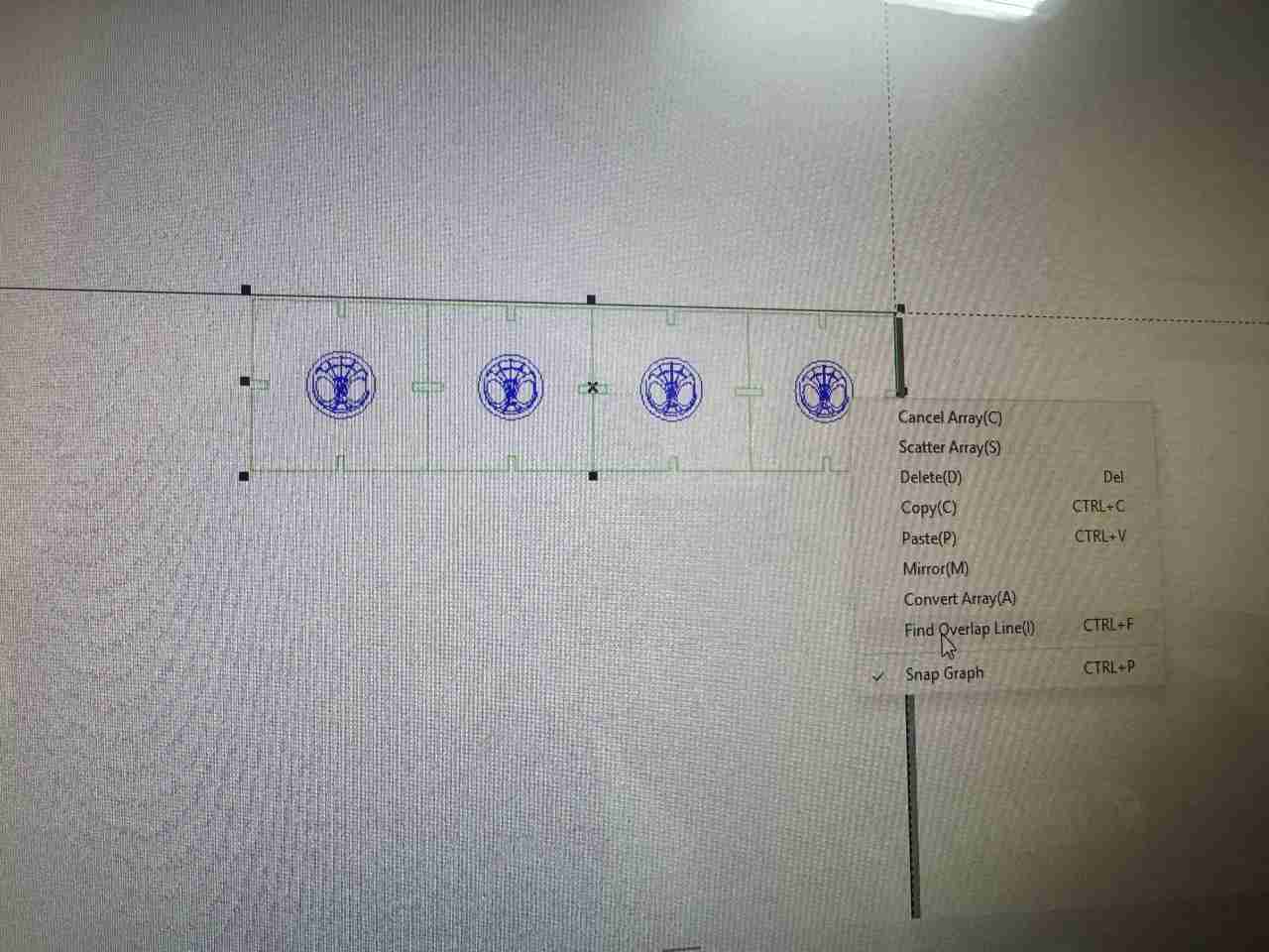
You will select delete all and the program will delete this lines.
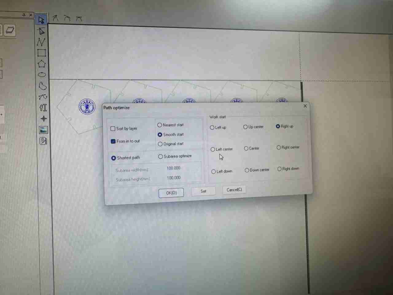
5.2.4 Optimize path tool
This tool allows the machine to take the best route to get better results while cutting and engraving. To use it you will right click the object and select Optimize Path.
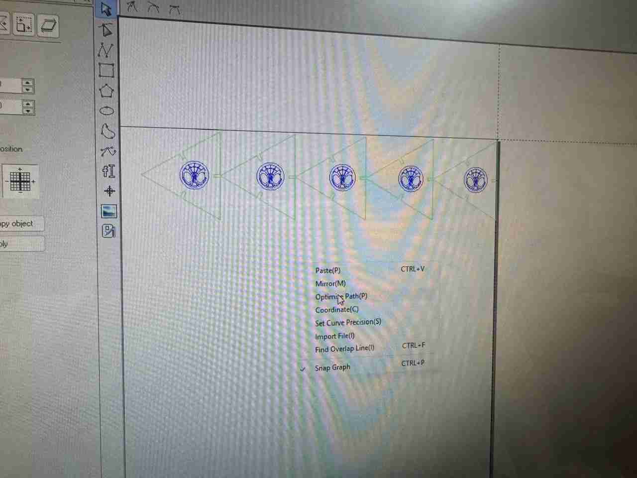
Then a tab will show to ask if you want to make some changes, normally you will just leave the default configuration.
5.2.5 Save oud files
oud files are the type of files that the laser cutter uses to function. To save this file with that format you will go to the tab on the right side and click Load file then you will save it on a USB device to connect it to the machine. Make sure that the name or your files if not the machine will only show the file that was created first and you should leave it out so you don't have to enter on folders.
6. Using the laser cutter
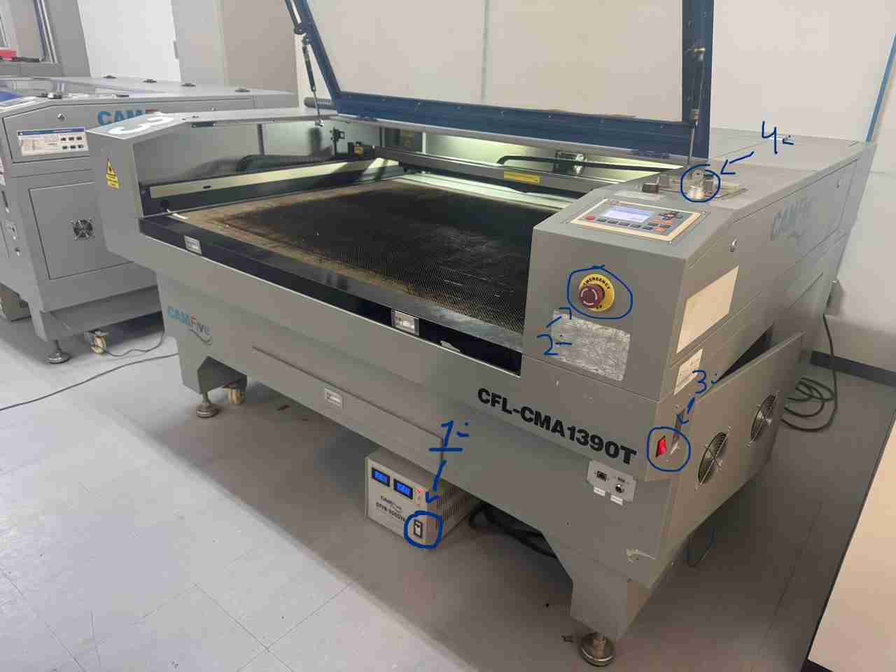
6.1 Turn on the laser cutter
For this step I will explain it with no great details since is documented in the group assignment if you want more information you can check the group assignment of the 3rd week.
- Turn on the objects in the order that appears on the photo
6.2 Read the files
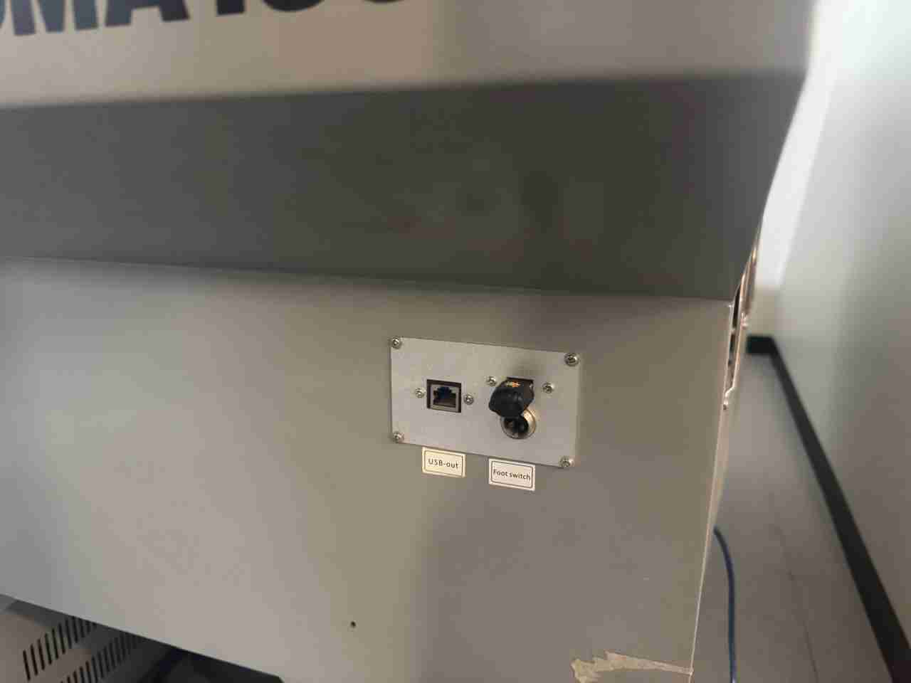
For reading the files you will use your USB with the loaded files, in my case I'm using the CFL-CMA1390T this laser cutter has the input of the USB in the middle of the right edge.
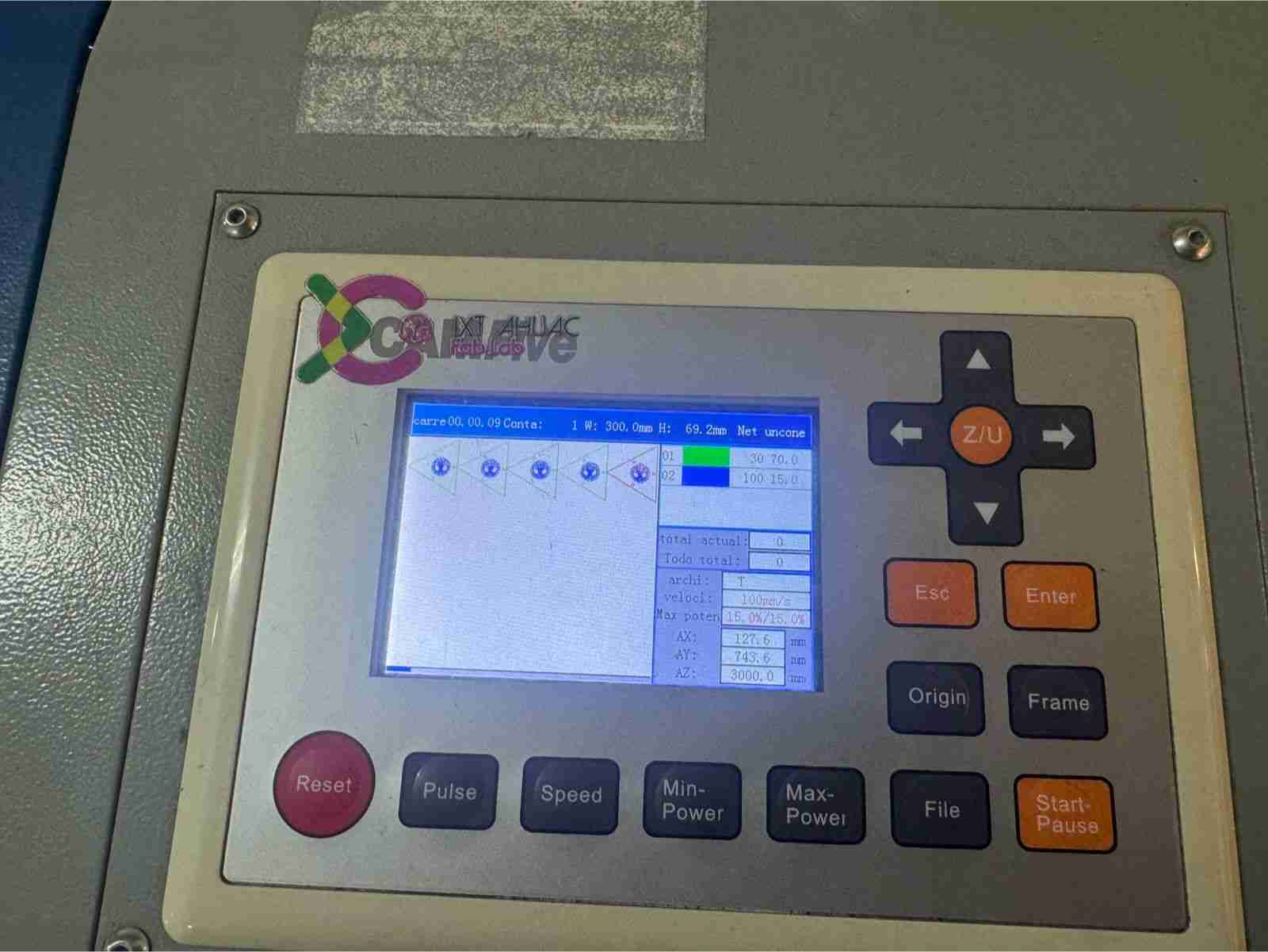
After that you will use the screen and buttons to save your file on the machine. The steps are file, right, Udisk+, enter, read, select the file, right, copy to RAM. Then you can press esc until you are on the blank main window. Finally you will press file and the file that you just copied should appear you will press enter.
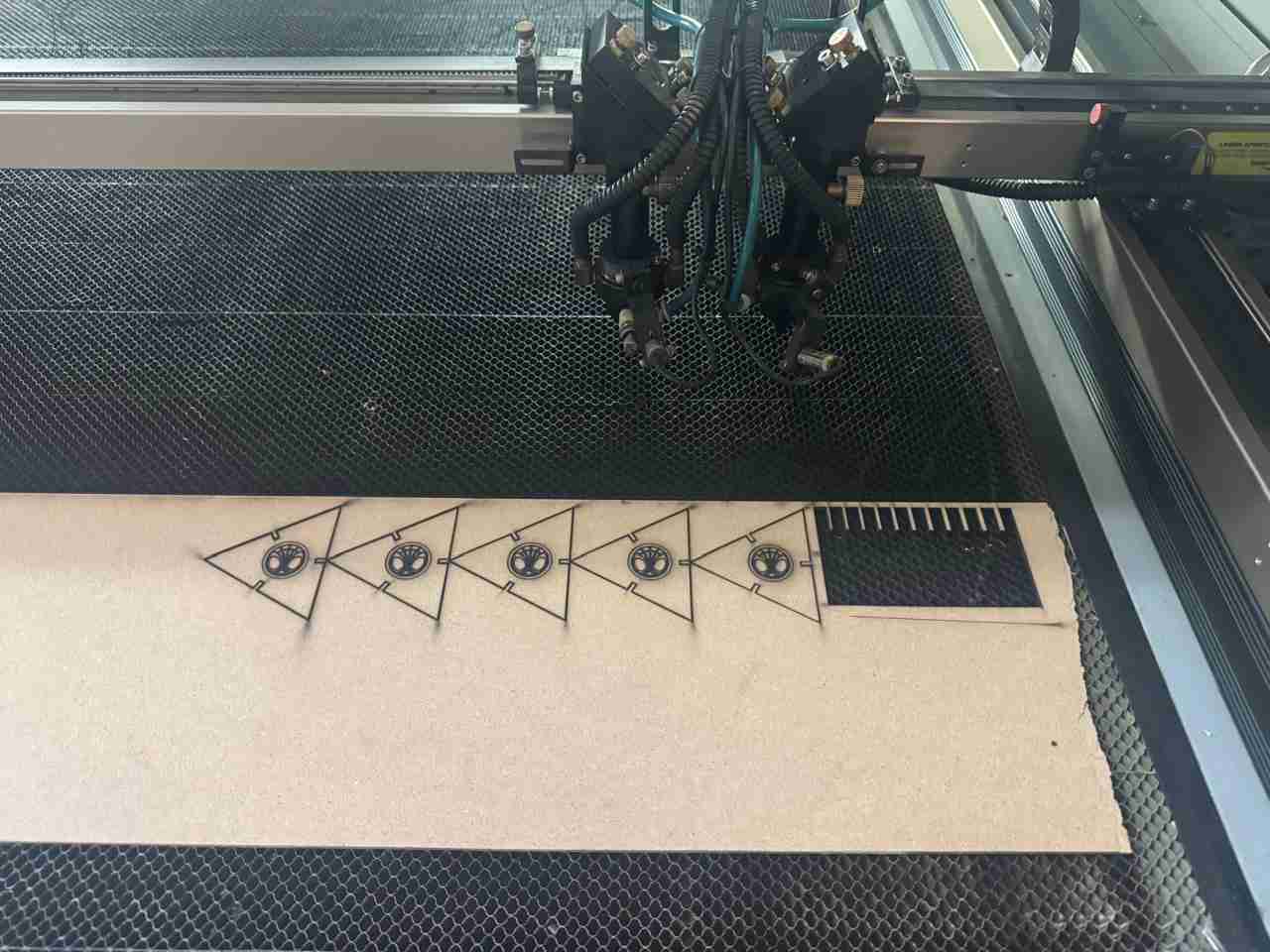
6.3 Cutting the piece
You will place your material on the laser cutter and select the origin you want by moving the laser with the arrows on the screen (the origin will normally be the bottom corner, top corner, or the flat edge where you just cut), once you have copied your file, (open it by pressing file and the file should appear you will press enter) you will press Frame if the laser gets out of the material you must move your materail or get more material in order for the laser to fit but if it doesn't get out of the material you can continue. Now you can push Start to start curring and engraving
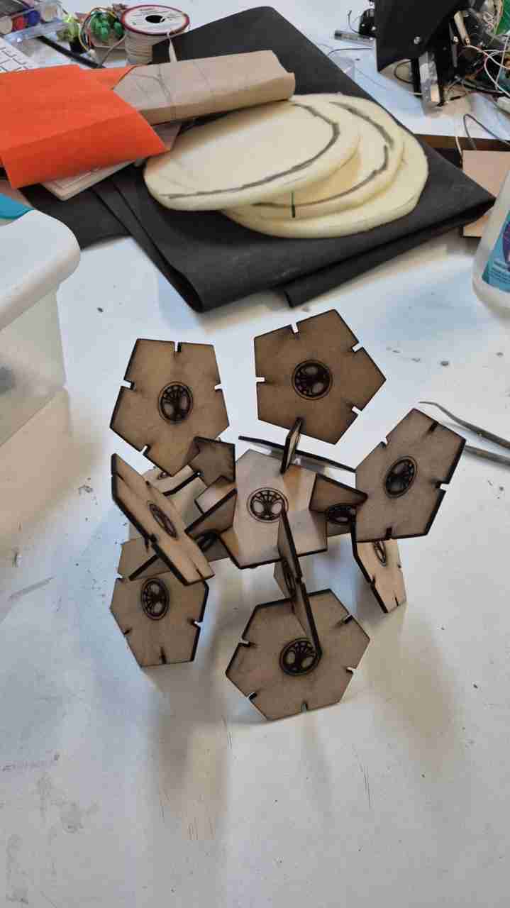
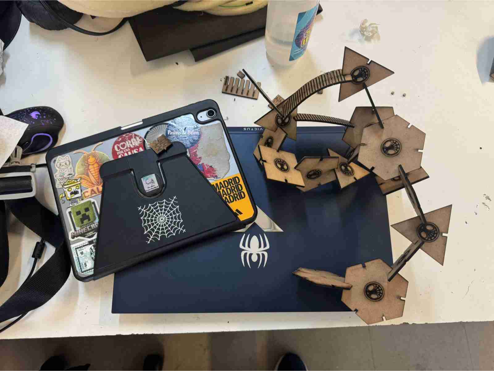
Here is the result of the newly cut and engraved pieces.
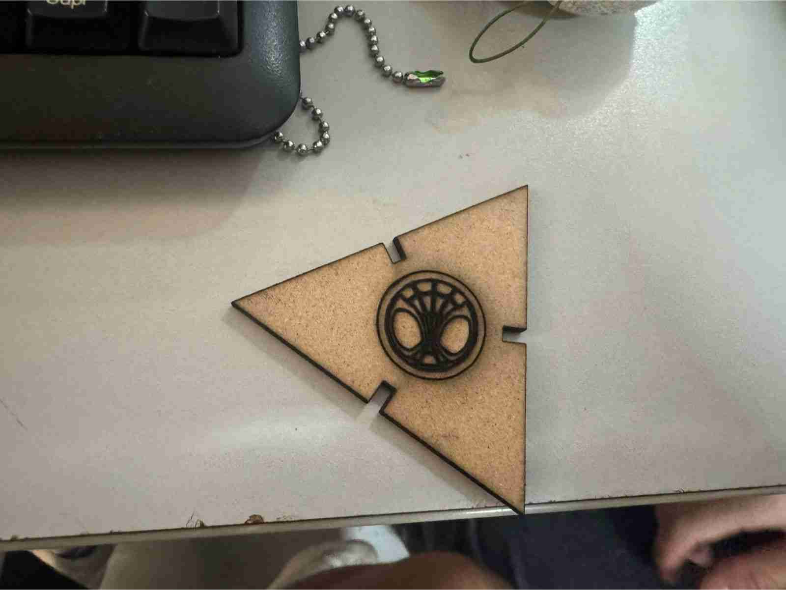
Here is the piece to have a better individual look
For all the pieces you need to repeat this process until you finish.
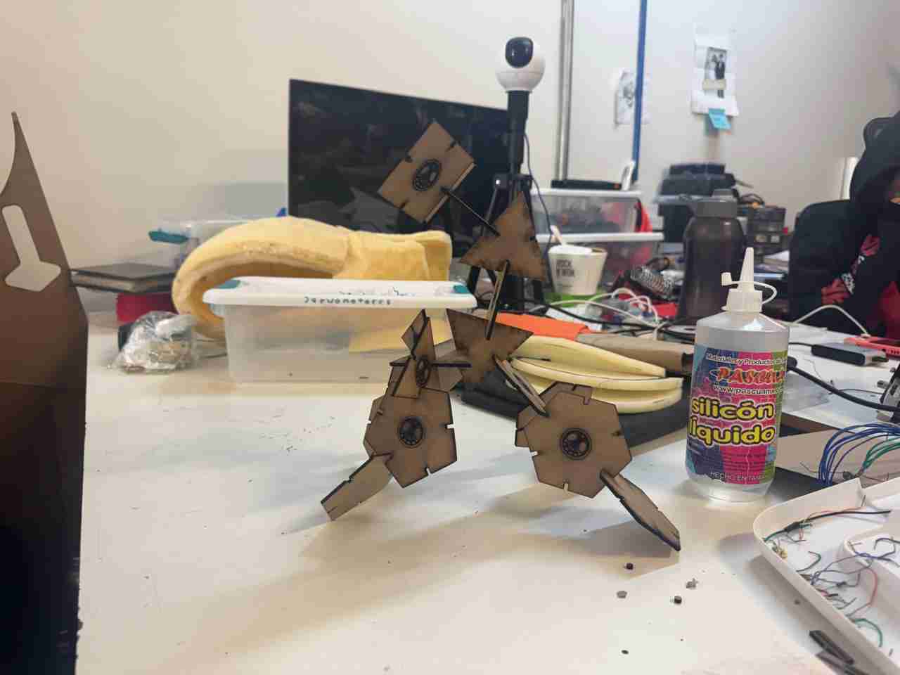
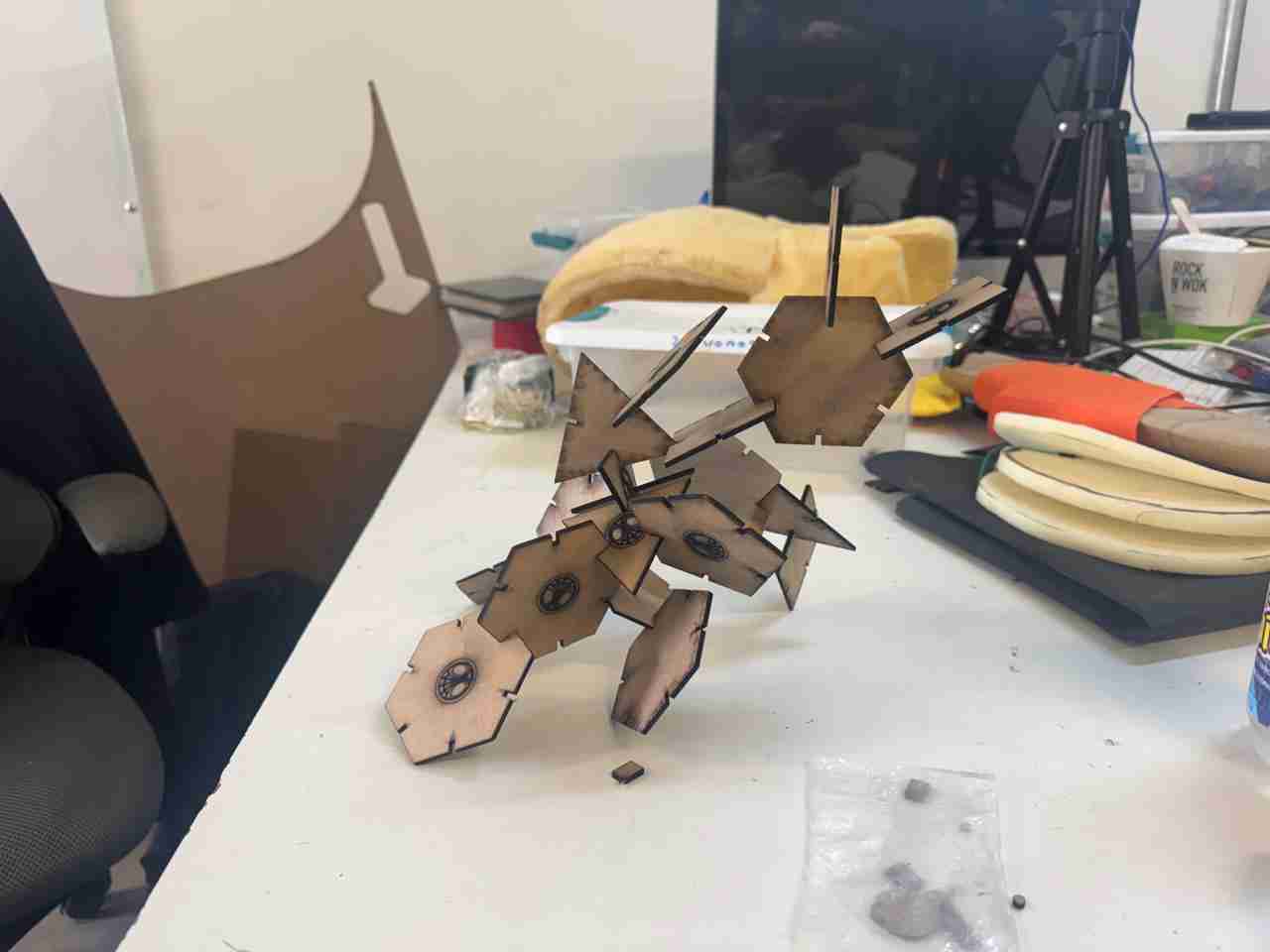
One of the many ensembles it has.
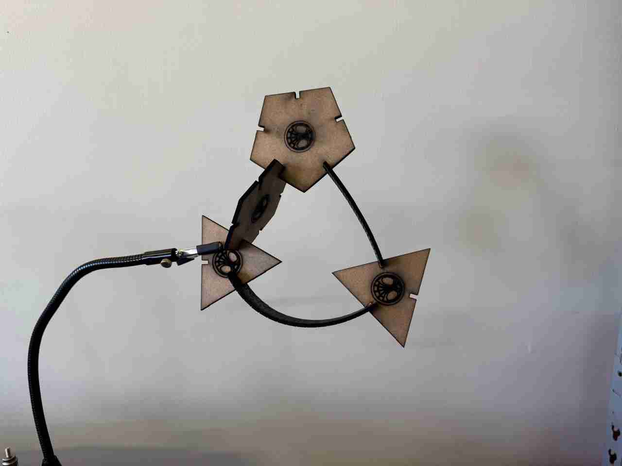
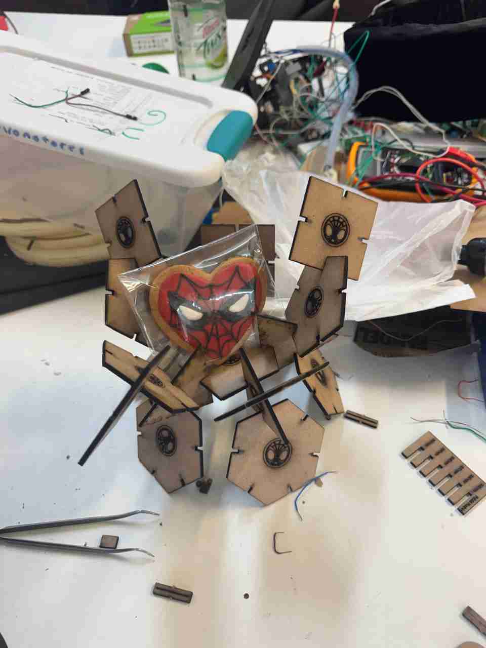
Here are some photos of different figures that my friends assemble with my kit.
6. Vinyl
6.1 Using the vinyl cutter
6.1.1 File preparation
The vinyl cutter admits SVG files so I will use the files that I made during the 2nd week.
To use the vinyl cutter, you'll need to add the necessary drivers, that are plotter plotting driver After adding them, create a new file, scaling the paper size to match the size of your vinyl. Then, copy and paste your SVG file into the new file and position it in a corner of your paper to minimize vinyl waste.
imagen de temasFinally you can send the file to the vinyll cutter when the vinyll cutter is connected.
6.1.2 set the vinyll
The vinyll vutter that I will use is from the brand STM ROBOTICS this machine has 2 wheels that act as a vinyl press and also help the vinyl move so that it slides through the machine, so when placing our vinyl we have to move these presses so that our vinyl fits correctly.
You cand define the origin of the machine with the buttons on the right by double pressing the origin button. After you define the origin you can also modify the preasur and load of the cutter part. You will reduce speed and increase force when the vinyl is wrinkled
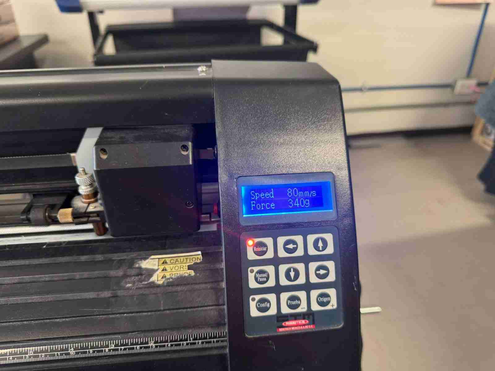
If your vinyl is wrinkled it may cut and wrinkle the figure.
6.1.3 Cutting
Once we have setted up the machine and our file, we connect the machine and a computer to load the file and start cutting
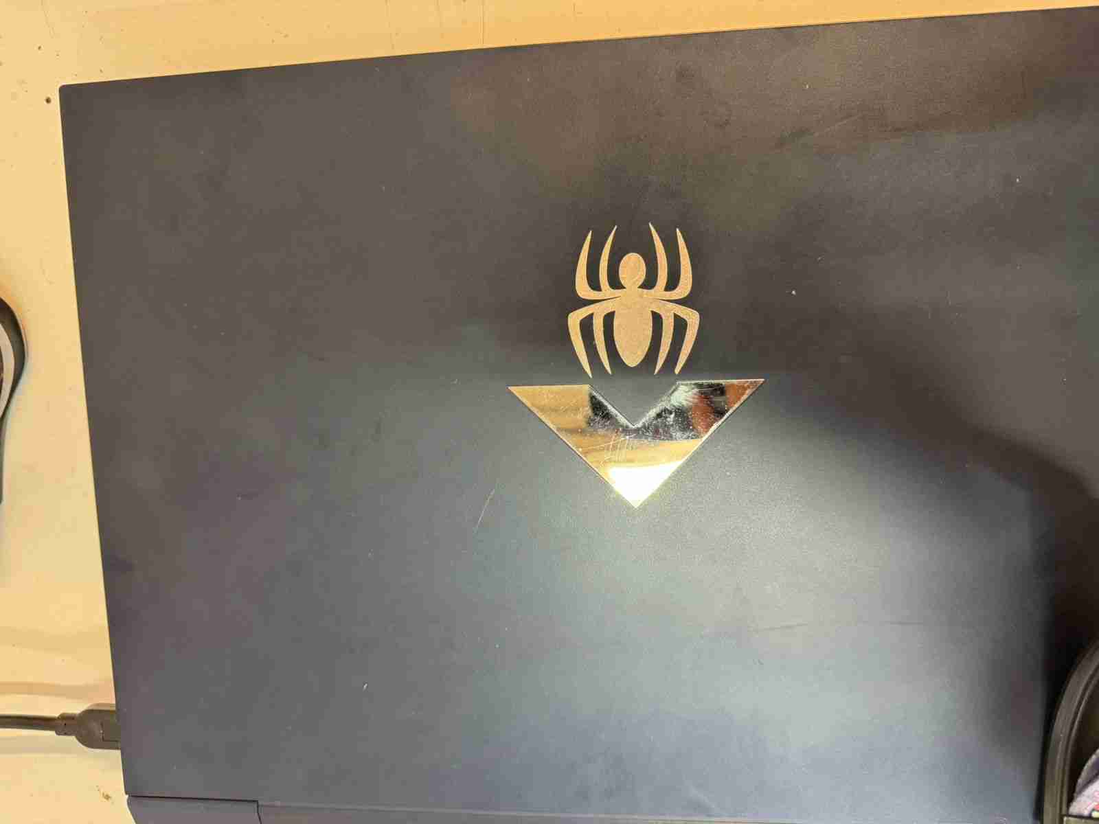
I also made the spider-man logo
Here is the result of the spider-man vectorized image
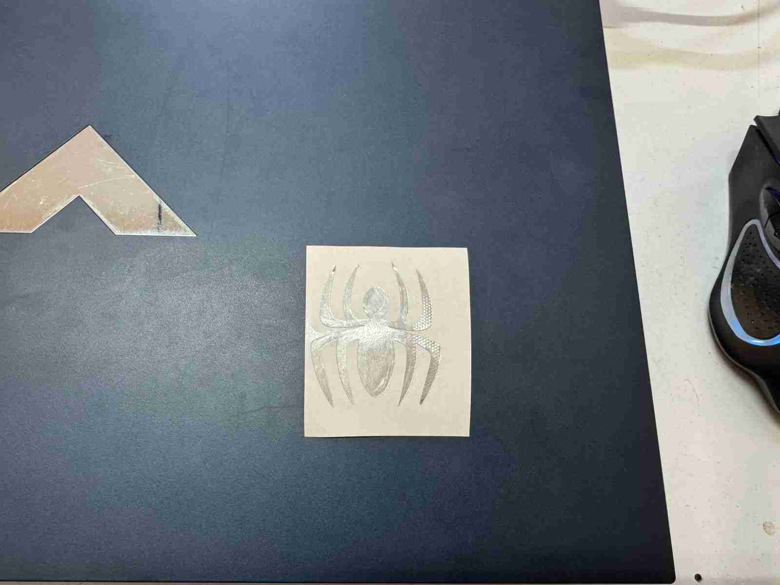
Because this vinyl was long enogh I didn't have to use transfer paper to paste it on my PC, my fingers were the only thing used.
6.2 Using the vinyl as skickers
To make your vinyll logos on sticker they can be stickers using transfer paper, as this has a light adhesive but with enough strength to stick the sticker to any surface.
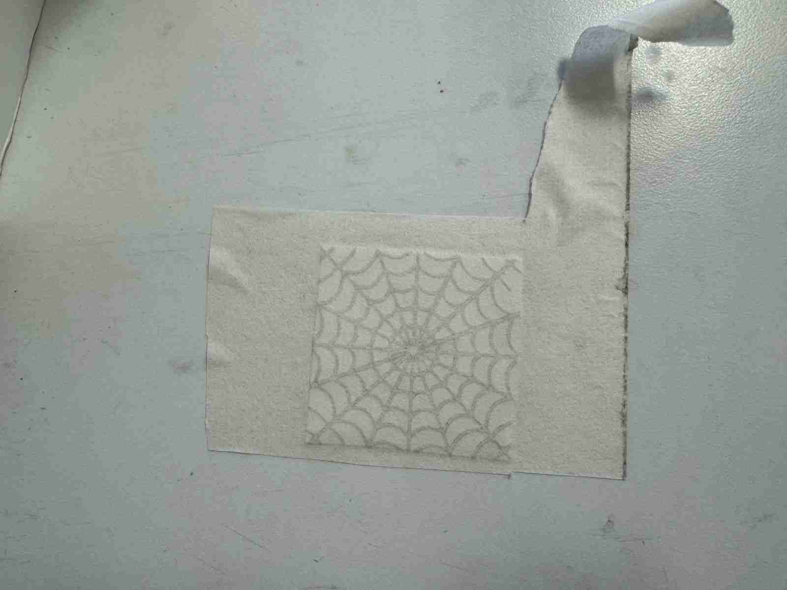
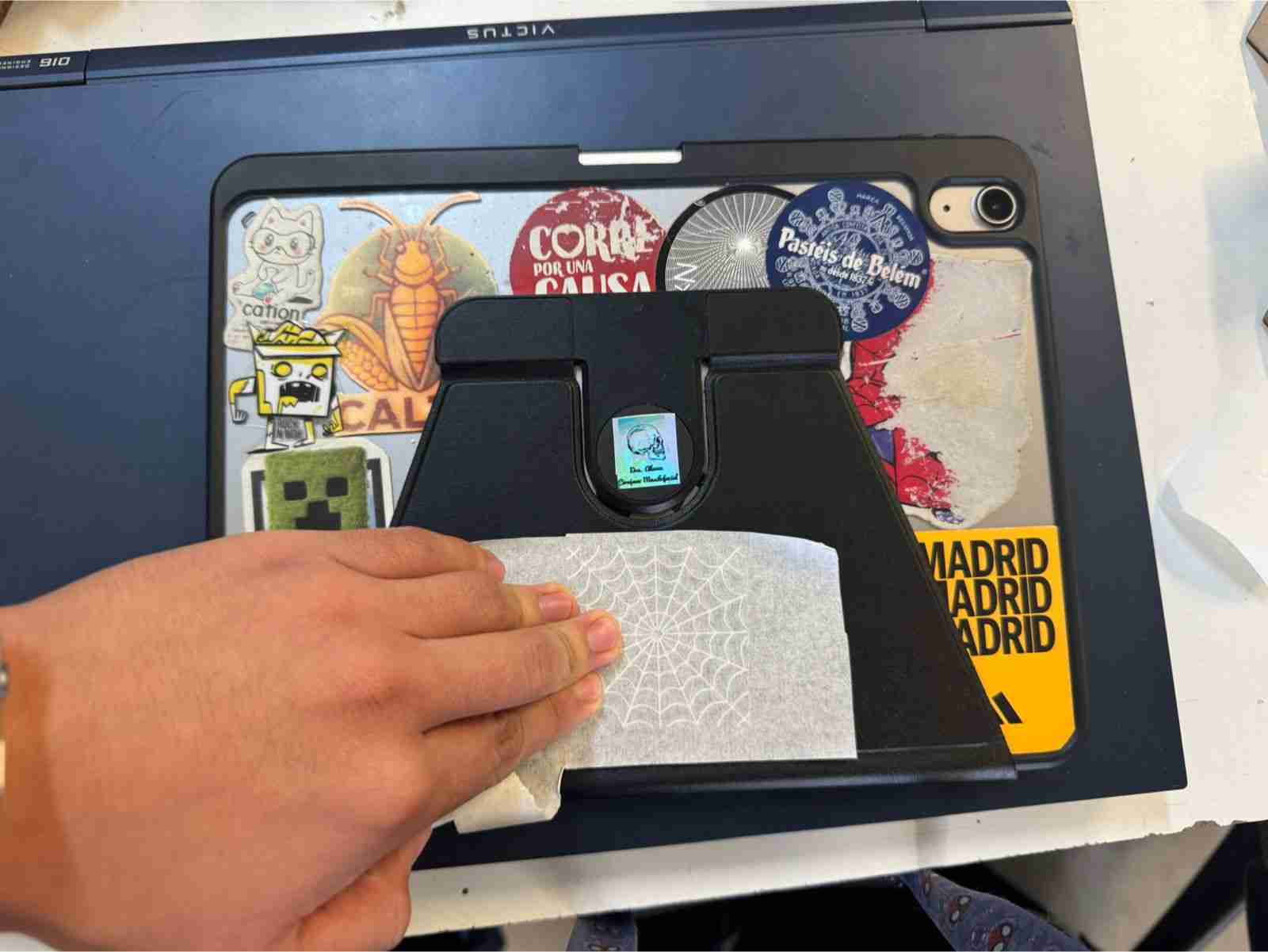
6.2.1 Remove the gaps
I will use my spiderweb pattern as an example; first, we need to remove what we don't need, such as the gaps between the spiderwebs. I recommend to use a cutter to remove this gaps.
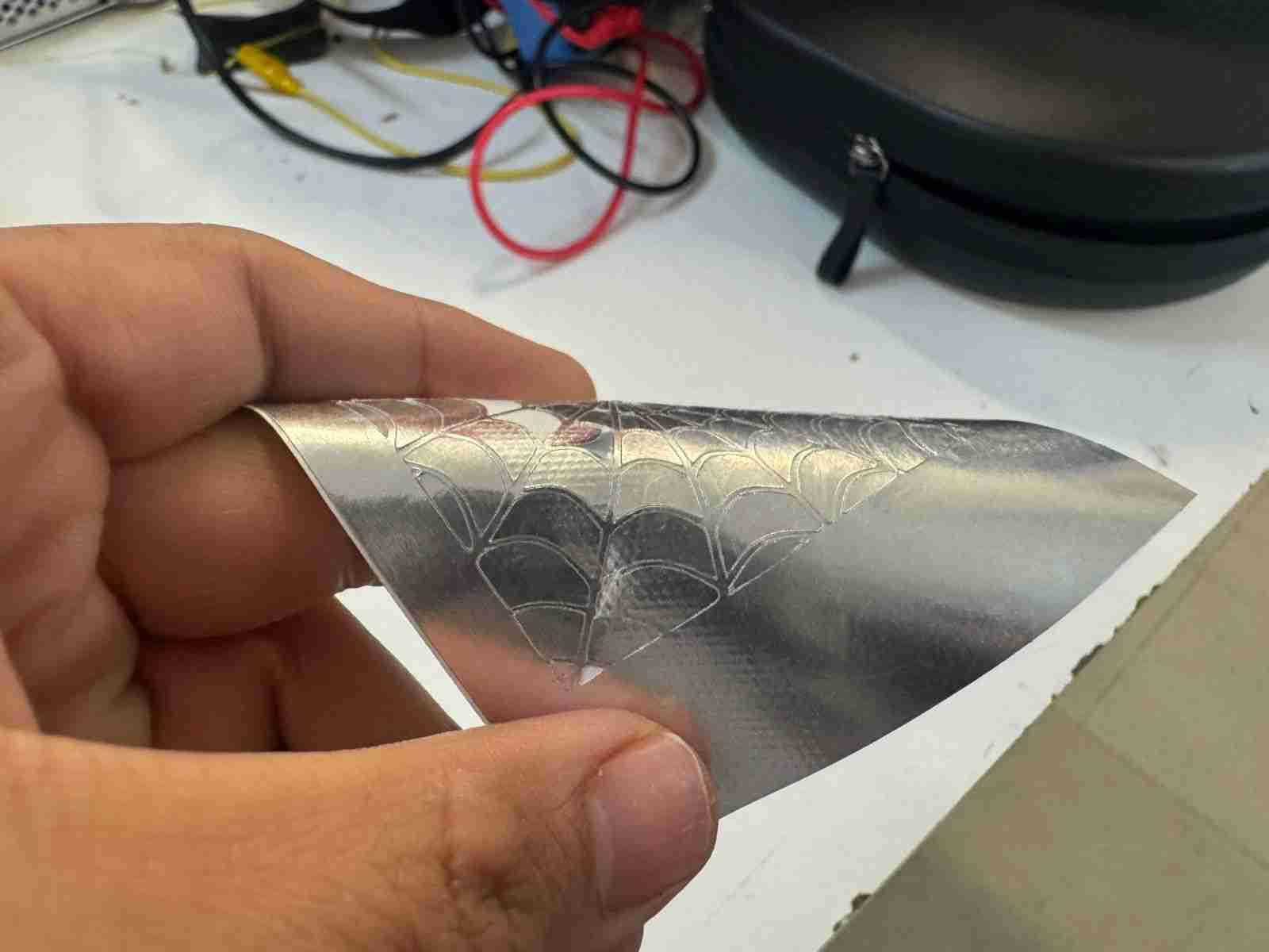
After we remove the gaps we are ready for the next step.
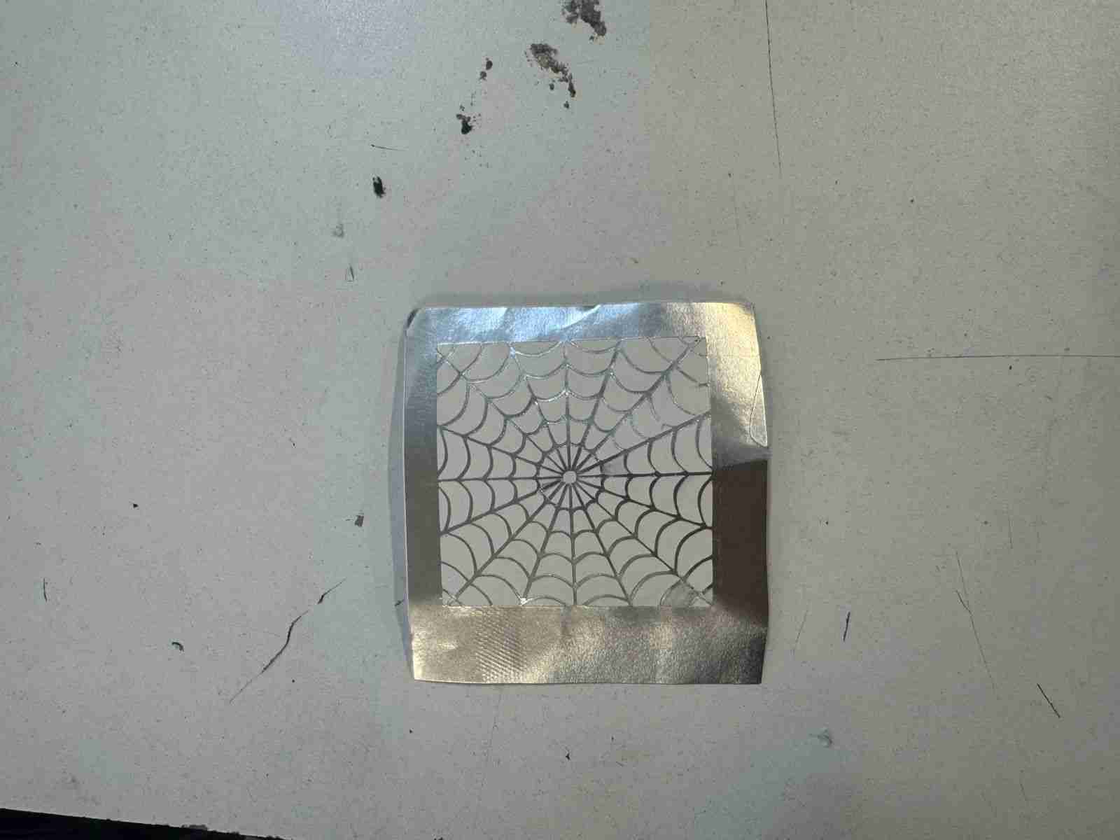
6.2.2 Paste the sticker on transfer paper
Now we will stick our vinyl to the transfer paper and apply pressure so that it adheres well to the paper.
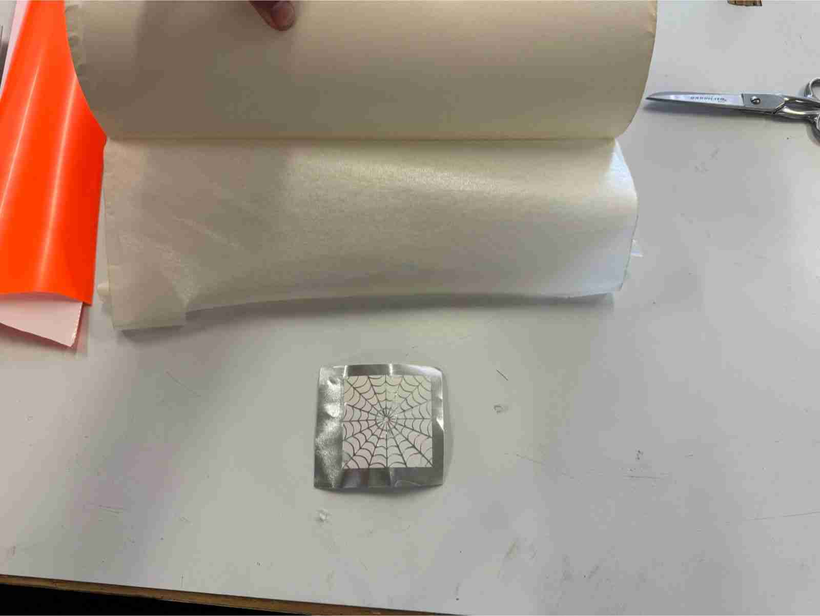
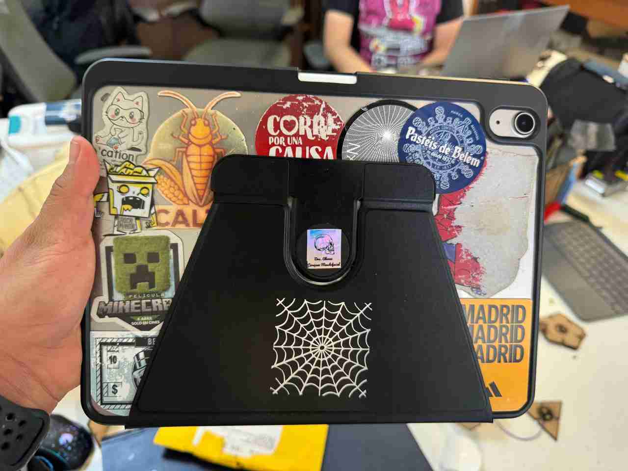
6.3 Use wherever we want
Now we can use this as a sticker to apply it anywhere, you just need to apply preasure and remove the transfer paper.
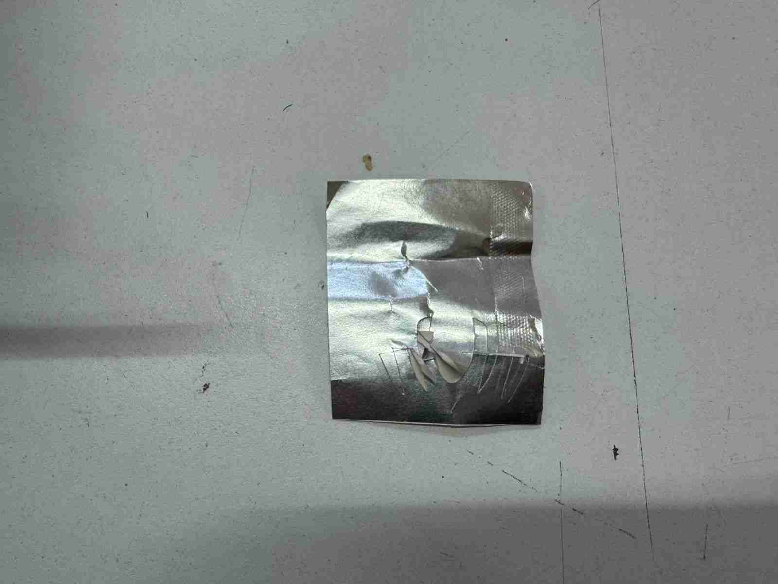
These are both results of the 2 stickers I made, both were made the same way.
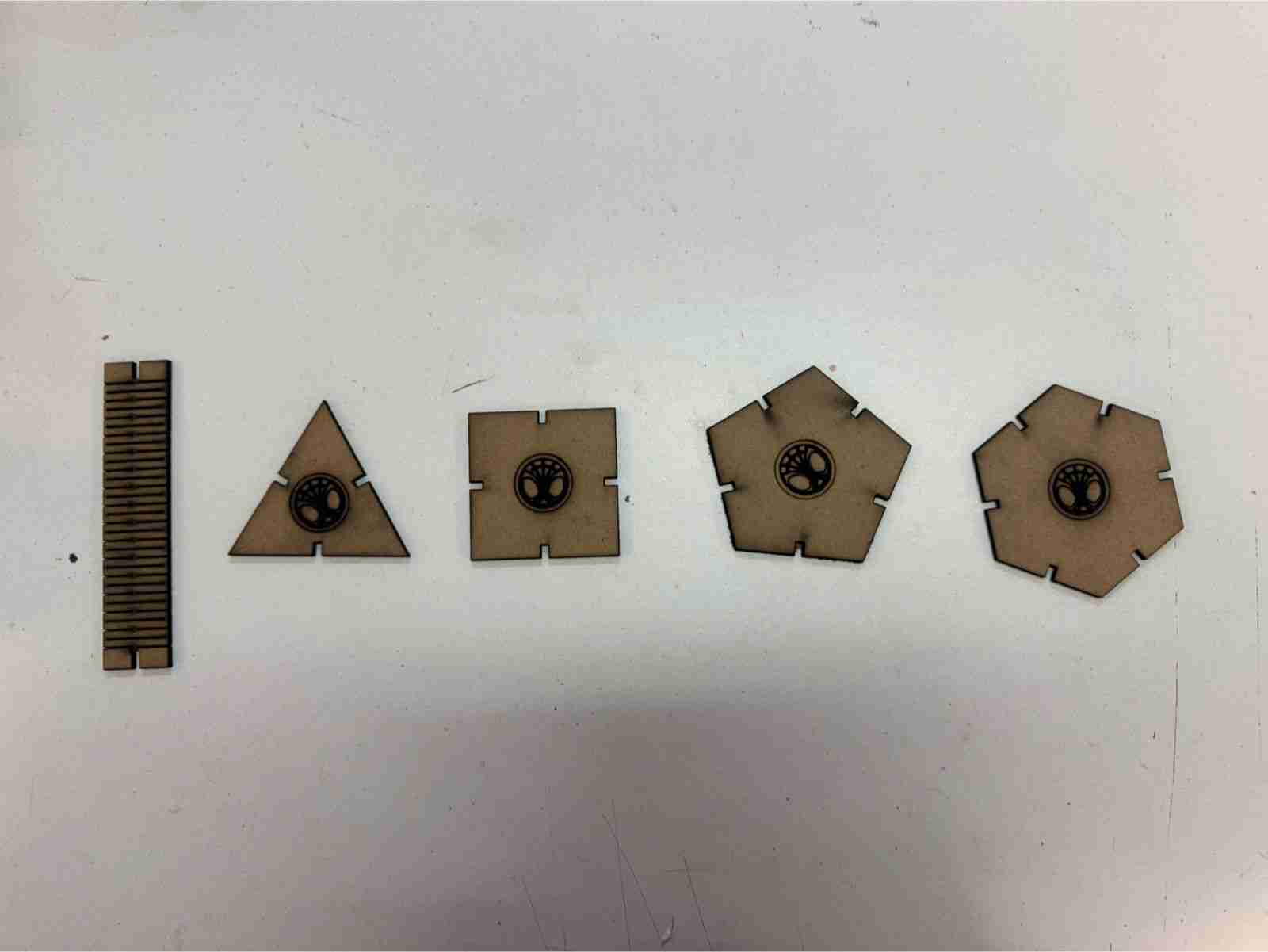
7. Final results
This photo includes all the products developed for this week.
8. Files created
Click on the "Download ZIP" to download all the files I made for this week assignment