Group Page
- Measure the power consumption of an output device.
- Document your work on the group work page and reflect on your individual page what you learned.
What I knew before this week:
- I had previously worked with and was already familiar with CNC machines.
- I already had prior experience with stepper motors, as I used them during my "Outputs" week.
- Thanks to Fab Academy, I already had the necessary knowledge to fabricate printed circuit boards (PCBs).
Stepper Motors
For the stepper motors section, we built the modular board, which is made up of two parts: the first contains the microcontroller connected to male pins to be linked via jumpers to the second part, which holds the drivers that control the stepper motors. Both boards were designed in KiCad.
Breadboard Test
I ran a breadboard test to verify that both stepper motors were properly connected and, if not, to make corrections and re-test.
This also helped me set the correct voltage on the potentiometer.
[Video 1 — Breadboard test]
The code to move the motors looks like this:
[Video 2 — Code to move the motors]
Microcontroller Board
This board uses a Raspberry Pi Pico 2. Its main parts are divided into four different sections:
- Power Supply: Provides 12V to the board, steps that voltage down to 3.3V to power the Pico safely, and passes that same 3.3V to the driver board.
- Microcontroller: Houses the Raspberry Pi Pico with its corresponding male pin headers assigned.
- Motor Drivers: Contains the footprints for the male pin headers that the board uses to connect via jumpers the 3 motor control pins: STEP, DIR, and ENABLE.
- Zero-ohm resistor (acts as a bridge between grounds to allow a trace to pass through the design), a diode (to prevent reverse current and avoid damage), and an LED (to confirm that voltage is reaching the board).
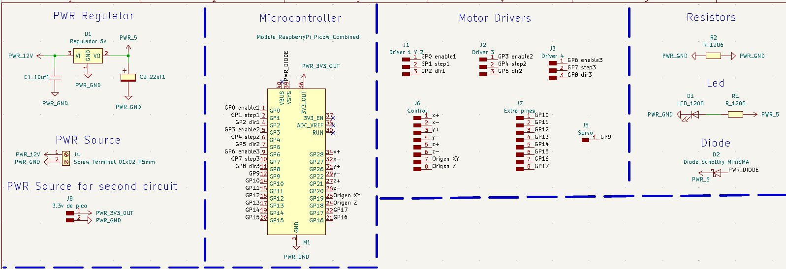
Final schematic design of the microcontroller board in KiCad.
The assembled board looks like this:
Driver Board
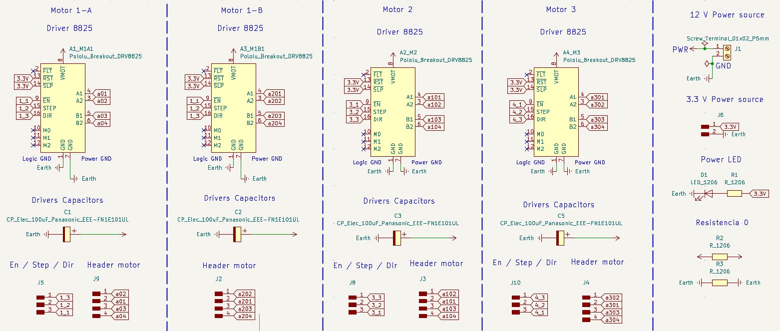
Board Schematic
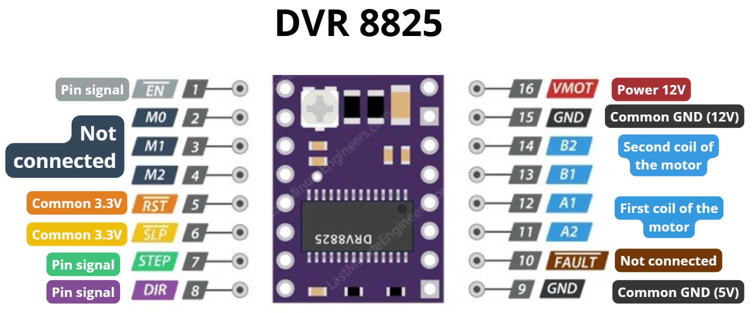
The drivers used to control the stepper motors are the DRV8825, and the stepper motors are NEMA 17.
The wiring diagram for the DRV8825 drivers is as follows:
The way stepper motors operate is shown in the following image.
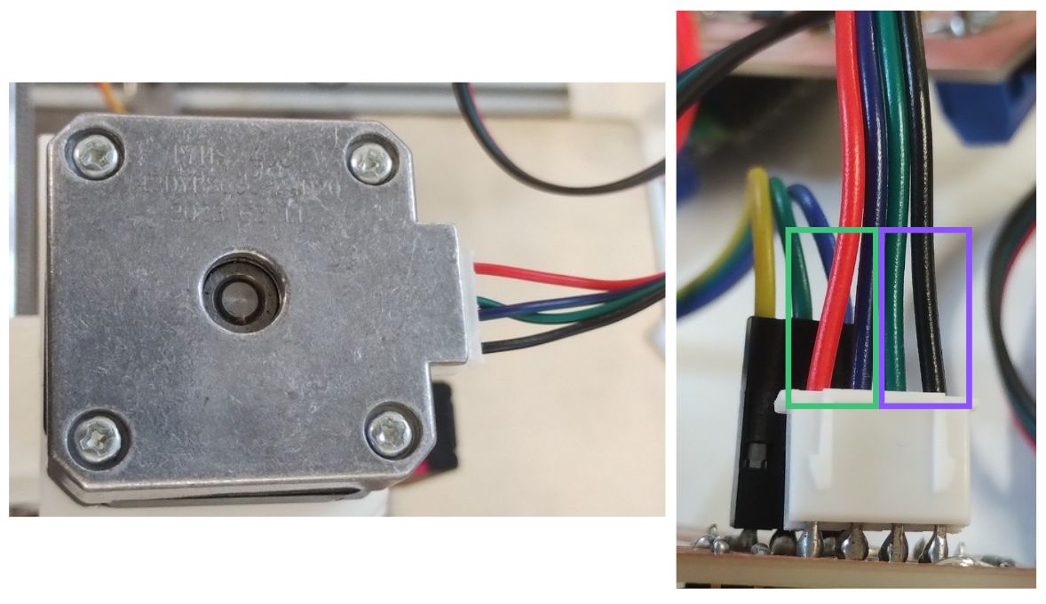
- Green: The green-marked wires correspond to the motor's first coil.
- Purple: These control the motor's second coil.
Note: The connector going directly into the stepper motor has 6 wires, but the output connecting to the board uses only 4 pins.
Component Table in KiCad
| Component (Value) | Search in "Place Symbol" | Footprint Name | Quantity |
|---|---|---|---|
| DRV8825 Driver | DRV8825 | Module:Pololu_Breakout-16_15.2x20.3mm | 4 |
| 100uF Capacitor (Electrolytic) | CP | PCM_fab:CP_Elec_100uF_Panasonic_EEE-FN1E101UL | 4 |
| LED | LED | PCM_fab:LED_1206 | 1 |
| Screw Terminal (2 pins) | Screw_Terminal_01x02 | PCM_fab:TerminalBlock_OnShore_1x02_P5.00mm_Horizontal | 1 |
| Pin Header (4 pins) | Conn_01x04 | PCM_fab:PinHeader_01x04_P2.54mm_Vertical_THT_D1mm | 4 |
| Pin Header (3 pins) | Conn_01x03 | PCM_fab:PinHeader_01x03_P2.54mm_Vertical_THT_D1mm | 3 |
| Pin Header (2 pins) | Conn_01x02 | PCM_fab:PinHeader_01x02_P2.54mm_Vertical_THT_D1mm | 1 |
| Resistors | R | PCM_fab:R_1206 | 3 |
With everything connected in the board schematic, it looks like this:
Mistake I made: In a previous board, I made the mistake of connecting M0, M1, and M2 incorrectly — my board failed to detect the signal and therefore the motor did not move.
It is not critical, as these pins only define the number of steps the stepper motors can be configured to. To set them, the corresponding pins must be enabled, as explained in the table below.
| M0 | M1 | M2 | Microstepping Resolution | Steps per Revolution (1.8° Motor) |
|---|---|---|---|---|
| Low | Low | Low | Full Step | 200 |
| High | Low | Low | Half Step | 400 |
| Low | High | Low | 1/4 Step | 800 |
| High | High | Low | 1/8 Step | 1,600 |
| Low | Low | High | 1/16 Step | 3,200 |
| High | Low | High | 1/32 Step | 6,400 |
| Low | High | High | 1/32 Step | 6,400 |
| High | High | High | 1/32 Step | 6,400 |
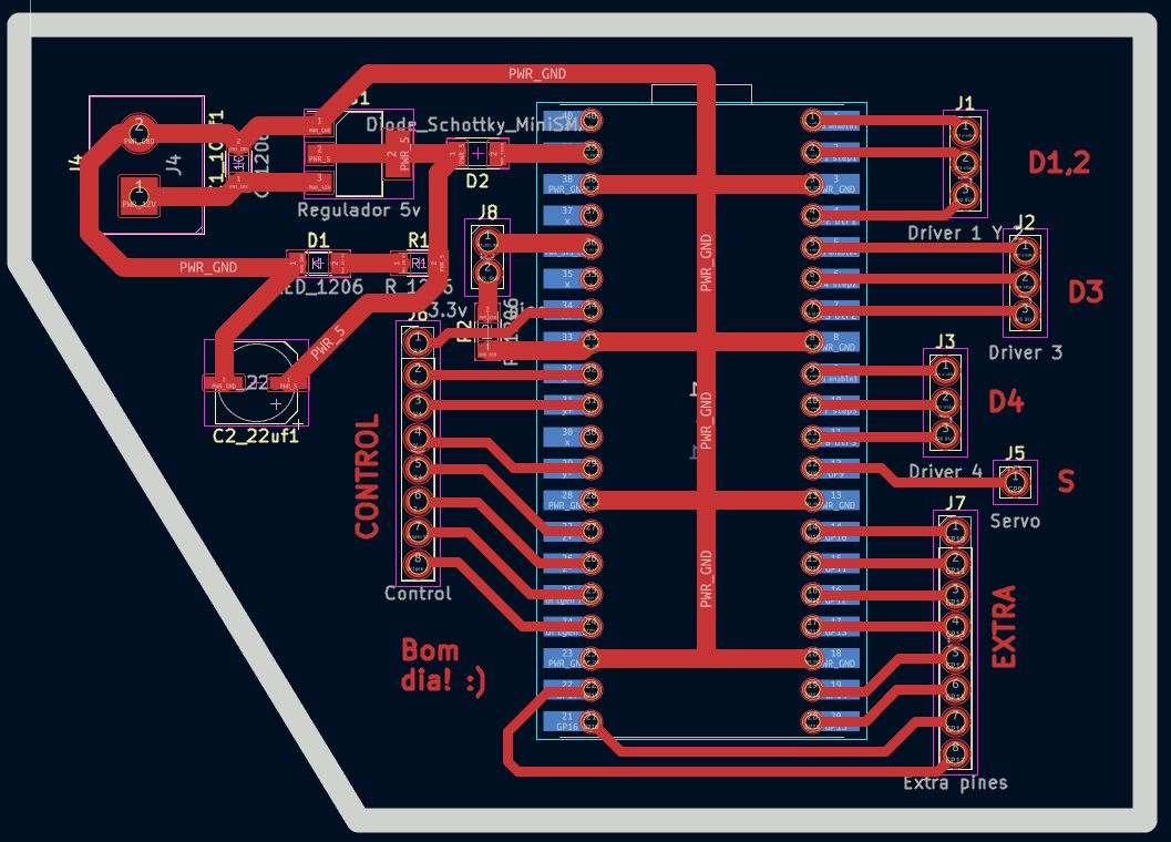
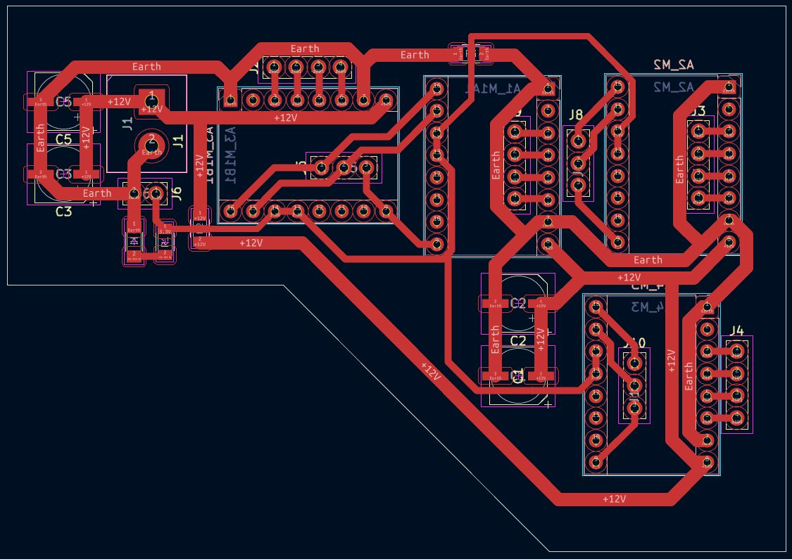
Board Editor
The trace parameters used were the following:
| Traces | Trace Width (mm) |
|---|---|
| Power and GND | 1.5 |
| All other traces | 0.8 |
Note: Zero-ohm resistors can help when you have no idea how to route a trace, but it is not considered good practice.
Three of the drivers have two strips of male pin headers connected to them.
- 4-pin strip: This one connects to the stepper motor cable.
- 3-pin strip: Connects each driver to a different signal for DIR, STEP, and EN.
Note: The drivers are flipped so they can be soldered from the bottom.
"Flip" Technique for Through-hole Components
To make soldering easier on a single-sided board, I placed the female pins (for drivers and MCU) on the back side. This allows the pins to pass through the board to be soldered comfortably on the copper side.
Design Note: This must be done before routing, as flipping creates a mirror effect on the pin layout.
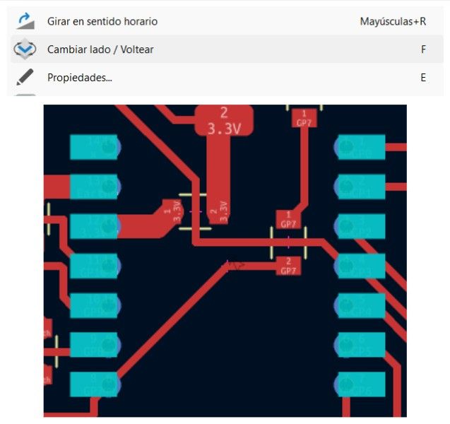
Flip technique applied
The final assembled board is the following:
Pin Declarations
This is how the STEP, DIR, and EN pins on the Driver Board connect to the Microcontroller Board.
| Axis | Component | STEP Pin | DIR Pin | ENA Pin |
|---|---|---|---|---|
| X Axis | Motor 1 (X1) | 16 | 17 | 18 |
| X Axis | Motor 4 (X2) | 7 | 8 | 6 |
| Y Axis | Motor 2 | 1 | 2 | 0 |
| Z Axis | Motor 3 | 4 | 5 | 3 |
Results
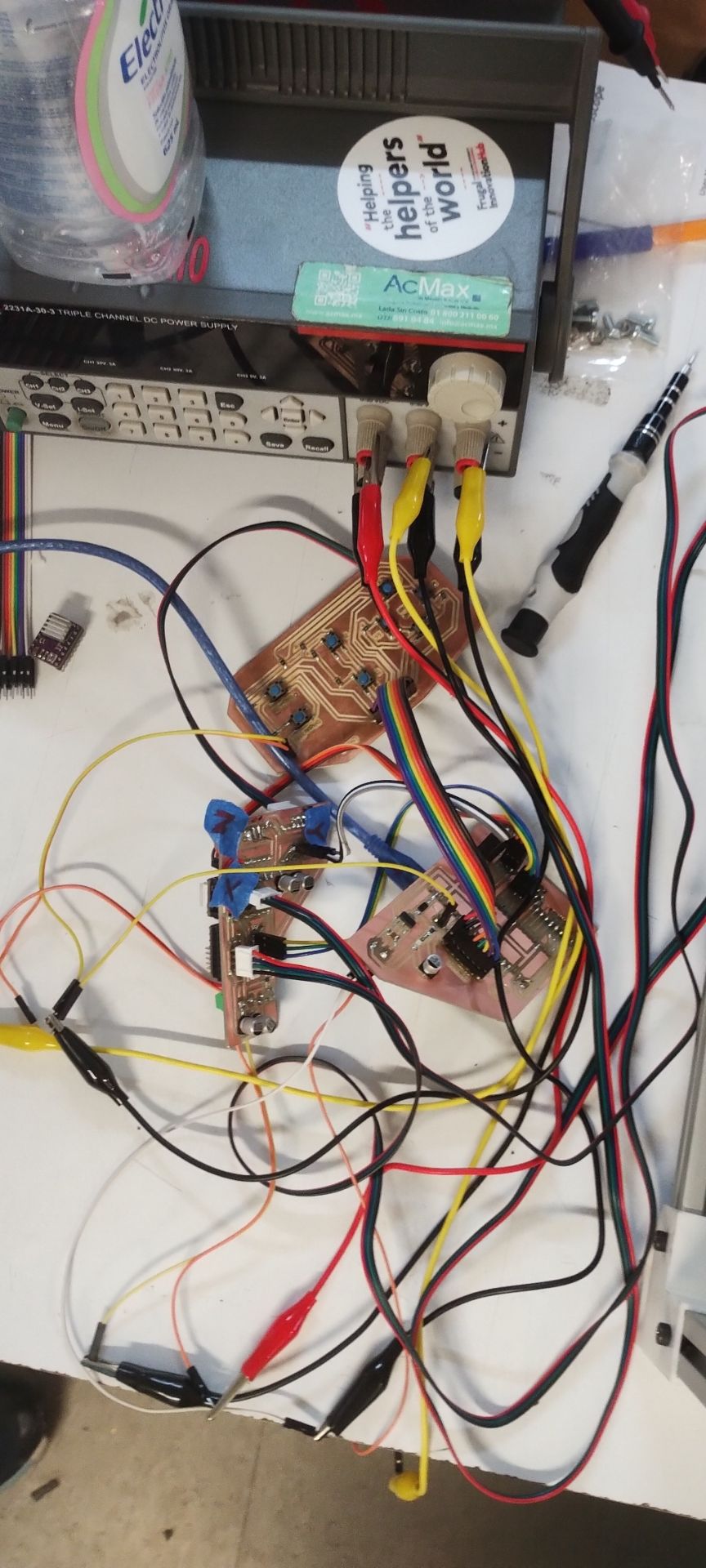
All boards connected
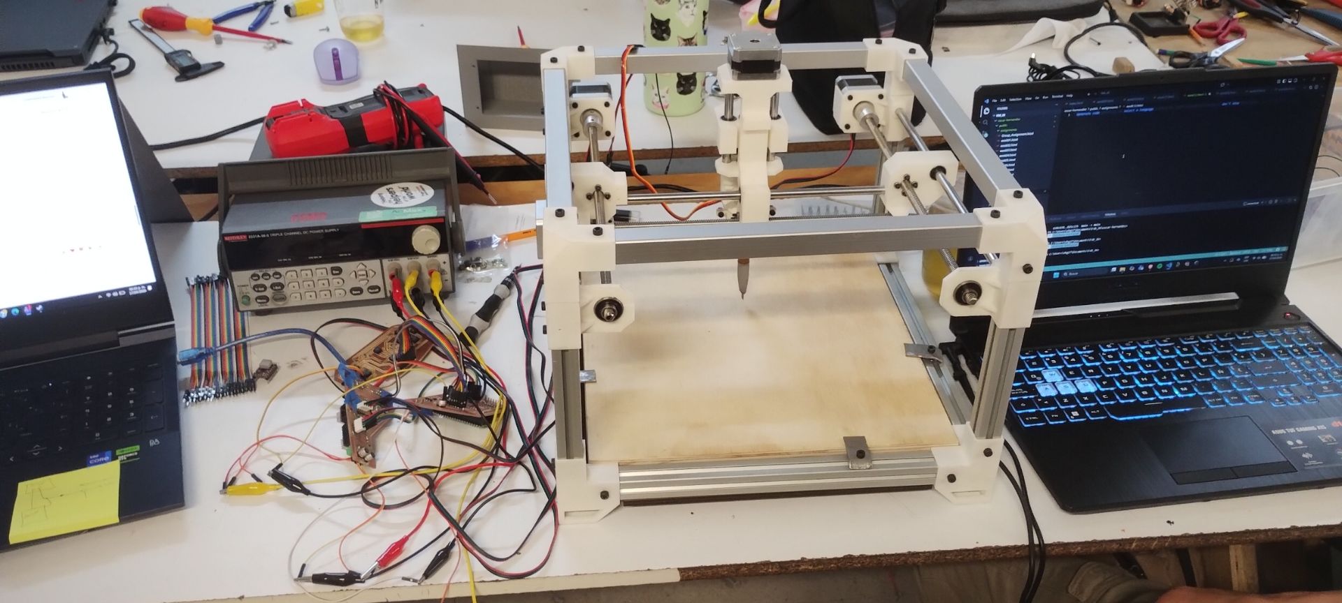
Boards connected to the machine
Code
#include <AccelStepper.h>

// =========================
// Motor 1 Pins
// =========================
#define STEP_PIN_1    D0
#define DIR_PIN_1     D1
#define ENABLE_PIN_1  D2

// =========================
// Motor 2 Pins
// =========================
#define STEP_PIN_2    D3
#define DIR_PIN_2     D4
#define ENABLE_PIN_2  D5

// =========================
// Motor 3 Pins
// =========================
#define STEP_PIN_3    D8
#define DIR_PIN_3     D7
#define ENABLE_PIN_3  D9

// =========================
// Motor 4 Pins (NEW)
// =========================
#define STEP_PIN_4    D10  // Change these pins according to your board
#define DIR_PIN_4     D11
#define ENABLE_PIN_4  D12

// =========================
// Motor Configuration
// =========================
#define FULL_STEPS_PER_REV 200
#define MICROSTEP          1

const long TEST_STEPS = FULL_STEPS_PER_REV * MICROSTEP;
const float MAX_SPEED  = 1000.0;
const float ACCEL      = 2000.0;
const float CONT_SPEED = 750.0;

// ── Four AccelStepper instances ───────────────────────────────────────
AccelStepper stepper1(AccelStepper::DRIVER, STEP_PIN_1, DIR_PIN_1);
AccelStepper stepper2(AccelStepper::DRIVER, STEP_PIN_2, DIR_PIN_2);
AccelStepper stepper3(AccelStepper::DRIVER, STEP_PIN_3, DIR_PIN_3);
AccelStepper stepper4(AccelStepper::DRIVER, STEP_PIN_4, DIR_PIN_4);

bool continuousMode = false;

// ── Enable / disable all four drivers at once ─────────────────────
void enableDrivers(bool enable)
{
  digitalWrite(ENABLE_PIN_1, enable ? LOW : HIGH);
  digitalWrite(ENABLE_PIN_2, enable ? LOW : HIGH);
  digitalWrite(ENABLE_PIN_3, enable ? LOW : HIGH);
  digitalWrite(ENABLE_PIN_4, enable ? LOW : HIGH);
}

void setup()
{
  Serial.begin(115200);
  pinMode(ENABLE_PIN_1, OUTPUT);
  pinMode(ENABLE_PIN_2, OUTPUT);
  pinMode(ENABLE_PIN_3, OUTPUT);
  pinMode(ENABLE_PIN_4, OUTPUT);
  enableDrivers(true);

  // ── Configure all four motors with the same parameters ──────────────
  stepper1.setMaxSpeed(MAX_SPEED);
  stepper1.setAcceleration(ACCEL);
  stepper2.setMaxSpeed(MAX_SPEED);
  stepper2.setAcceleration(ACCEL);
  stepper3.setMaxSpeed(MAX_SPEED);
  stepper3.setAcceleration(ACCEL);
  stepper4.setMaxSpeed(MAX_SPEED);
  stepper4.setAcceleration(ACCEL);

  Serial.println("DRV8825 + AccelStepper Test (4 motors)");
  Serial.println("Commands:");
  Serial.println("  1 -> one revolution direction 1");
  Serial.println("  2 -> one revolution direction 2");
  Serial.println("  3 -> continuous rotation direction 1");
  Serial.println("  4 -> continuous rotation direction 2");
  Serial.println("  0 -> stop");
}

void loop()
{
  if (Serial.available())
  {
    char cmd = Serial.read();
    switch (cmd)
    {
      case '1':
        continuousMode = false;
        stepper1.moveTo(stepper1.currentPosition() + TEST_STEPS);
        stepper2.moveTo(stepper2.currentPosition() + TEST_STEPS);
        stepper3.moveTo(stepper3.currentPosition() + TEST_STEPS);
        stepper4.moveTo(stepper4.currentPosition() + TEST_STEPS);
        Serial.println("One revolution direction 1 (4 motors)");
        break;

      case '2':
        continuousMode = false;
        stepper1.moveTo(stepper1.currentPosition() - TEST_STEPS);
        stepper2.moveTo(stepper2.currentPosition() - TEST_STEPS);
        stepper3.moveTo(stepper3.currentPosition() - TEST_STEPS);
        stepper4.moveTo(stepper4.currentPosition() - TEST_STEPS);
        Serial.println("One revolution direction 2 (4 motors)");
        break;

      case '3':
        continuousMode = true;
        stepper1.setSpeed(CONT_SPEED);
        stepper2.setSpeed(CONT_SPEED);
        stepper3.setSpeed(CONT_SPEED);
        stepper4.setSpeed(CONT_SPEED);
        Serial.println("Continuous rotation direction 1 (4 motors)");
        break;

      case '4':
        continuousMode = true;
        stepper1.setSpeed(-CONT_SPEED);
        stepper2.setSpeed(-CONT_SPEED);
        stepper3.setSpeed(-CONT_SPEED);
        stepper4.setSpeed(-CONT_SPEED);
        Serial.println("Continuous rotation direction 2 (4 motors)");
        break;

      case '0':
        continuousMode = false;
        stepper1.setSpeed(0);
        stepper1.moveTo(stepper1.currentPosition());
        stepper2.setSpeed(0);
        stepper2.moveTo(stepper2.currentPosition());
        stepper3.setSpeed(0);
        stepper3.moveTo(stepper3.currentPosition());
        stepper4.setSpeed(0);
        stepper4.moveTo(stepper4.currentPosition());
        Serial.println("Stop");
        break;
    }
  }

  // ── Run all four motors on each cycle ───────────
  if (continuousMode)
  {
    stepper1.runSpeed();
    stepper2.runSpeed();
    stepper3.runSpeed();
    stepper4.runSpeed();
  }
  else
  {
    stepper1.run();
    stepper2.run();
    stepper3.run();
    stepper4.run();
  }
}
What I learned during this group project week:
- I learned how to coordinate the comprehensive mechanical design of a machine, understanding how every part—from the MDF base to the 3D-printed components—must fit perfectly to enable motion.
- I discovered the importance of tolerances in 3D printing, adjusting designs to prevent warping and ensuring that mounts and bearings had a precise fit.
- I learned how to flip components in KiCad and how to create functional modular boards.
Files I used this week
These are the files I utilized for my assignments this week.
w11_machine_design_files.zip
Machine Design Files
- 01_placa_kicad: Driver board
- 02_svg_files: For fabrication
- 03_monofab: RML for MonoFab
- 04_arduino_code: 4-motor test script