My Final Project
Project Overview
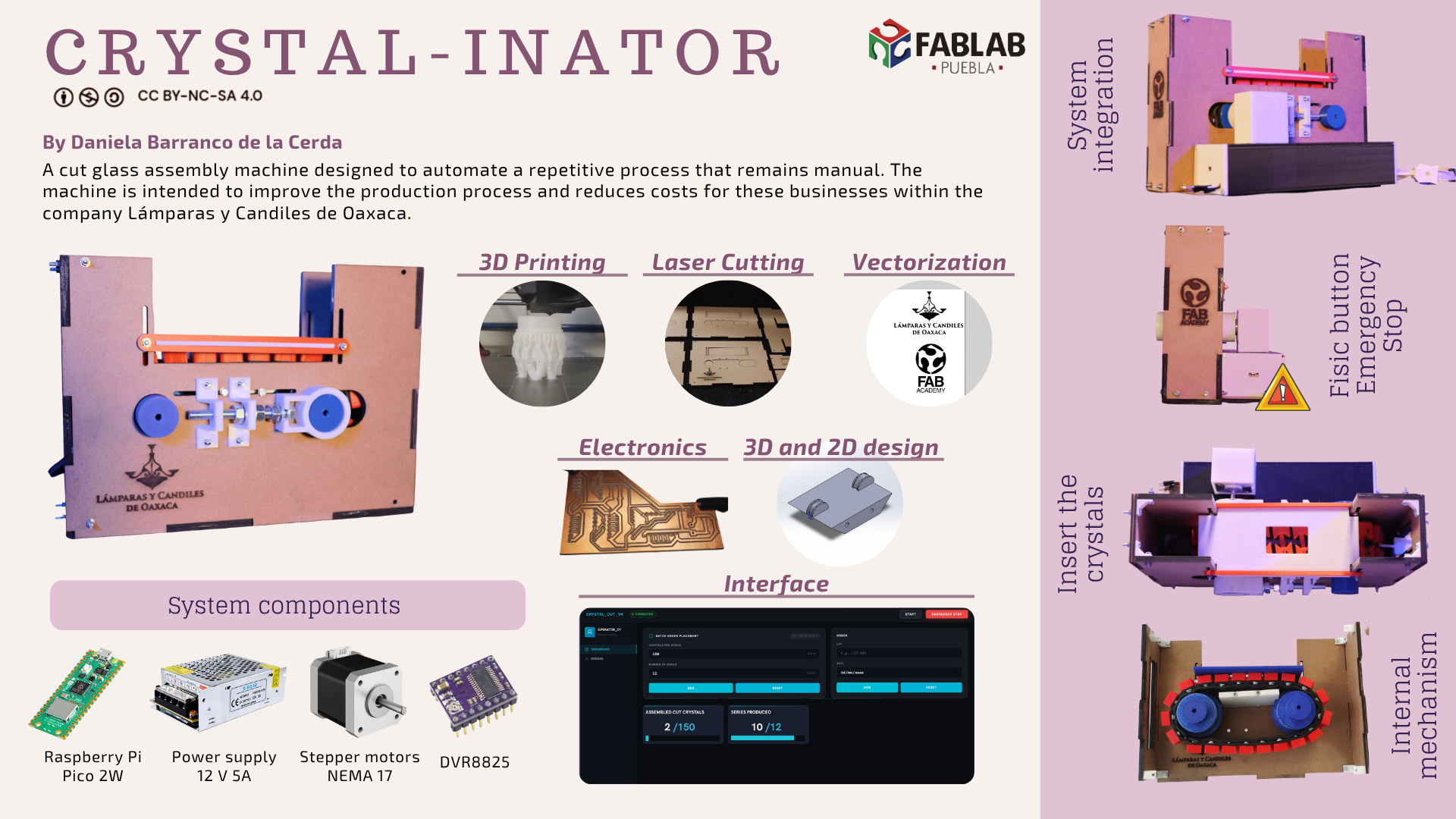
The project consists of a cut glass assembly machine designed to automate a process that remains manual for small and medium-sized enterprises. This accelerates production and reduces costs for these businesses. The machine is intended to improve the production process within the company Lámparas y Candiles de Oaxaca.
Final Project Slide Presentation
This is the presentation slide for my final project.
Final Project Video Presentation
This is the presentation video for my final project.
About the Company
It is my family's business, located in the state of Oaxaca, Mexico. We have more than 45 years of history, tradition and experience behind us. For this reason, I am happy and proud to be able to contribute today — with the knowledge I have acquired throughout my degree — to a business that watched me grow and that has given so much to me and my family.
"Illuminating Oaxacan homes since 1978."

Lámparas y Candiles de Oaxaca
We are an Oaxacan family business founded in 1978, and since then we have been illuminating Oaxacan homes with all types of residential light fixtures: ceiling, wall, table, and outdoor. We also offer an extensive variety of specialized lamp spare parts, such as: fabric and glass shades, switches, sockets, etc. We additionally provide repair, restoration, and maintenance services.
The customer is very important to us, so we create or source special products (spare parts, new models, etc.) to satisfy their tastes and needs.
Mission
To offer quality lighting products through warm and personalized customer service.
Vision
We seek to remain in the preference of Oaxacan consumers by staying at the forefront
of lighting and responding to the needs of our context.
The Problem to Solve
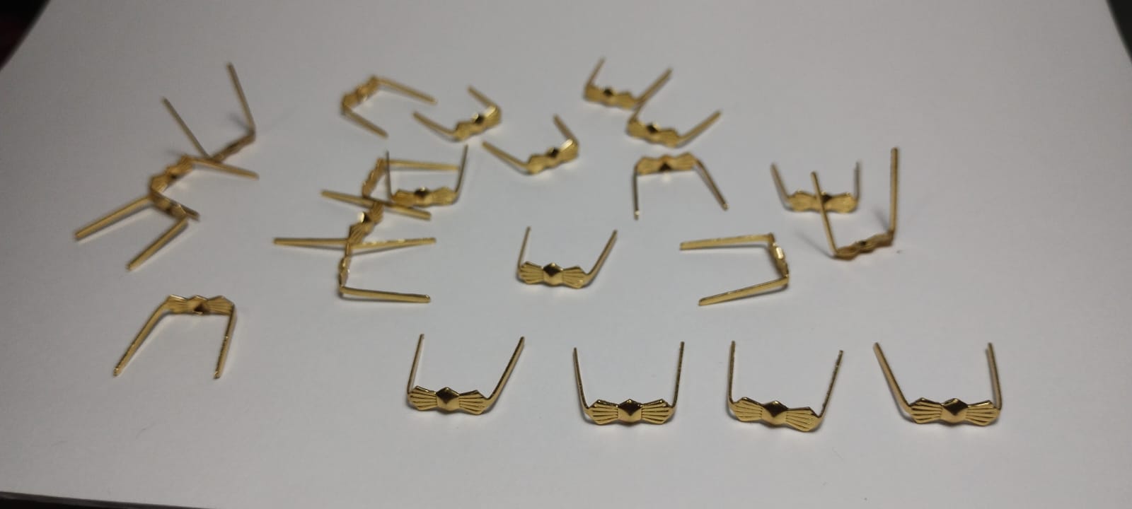
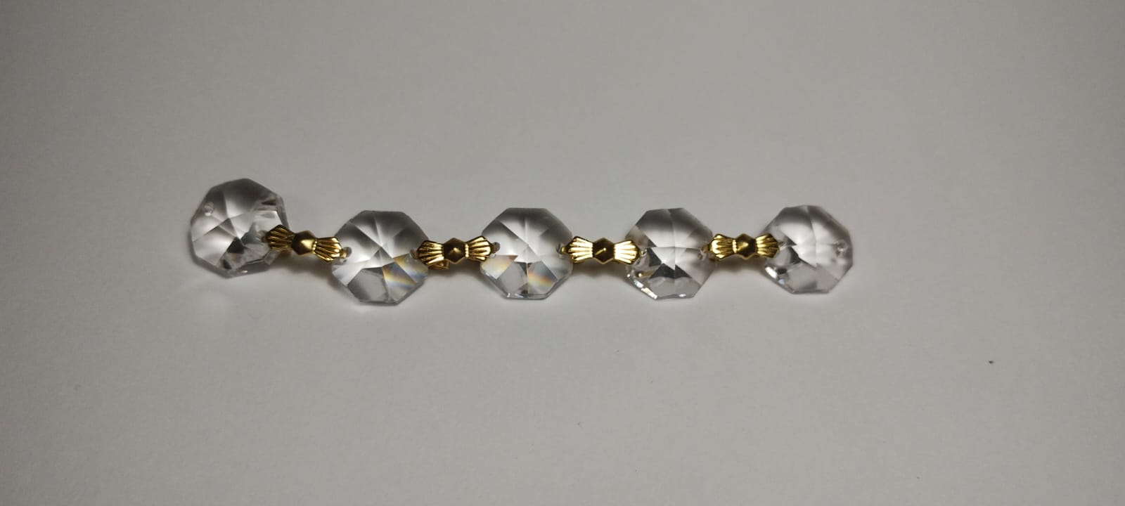
One of our products is the "Imperial Chandelier"; to give you an idea of their scale, they are frequently installed in churches. However, we only purchase the chandelier's metal frame. Separately, to "dress" the chandelier, we buy the crystals (made of cut glass) and the "bows," which are a type of staple used to link the cut crystals together.
While the supplier offers the chandelier fully assembled (already dressed), the price increases approximately fivefold. This leaves us with virtually no profit, as our selling price is nearly the same as their wholesale cost. On the other hand, the manual assembly process for the cut crystals takes about one week per chandelier; consequently, it is difficult to meet demand during peak sales seasons due to the time required for each piece. Furthermore, keeping them in stock fully assembled is not a viable option because they occupy too much warehouse space.


Production Process of the Chandelier
Step 1: Merchandise Acquisition
Our suppliers send us the skeleton (body) of the chandelier not assembled — all the parts come separately, so we always start by putting the structure together. However, the chandelier is very large, so it is not possible for us to keep all the assembled structures in our inventory at the same time.
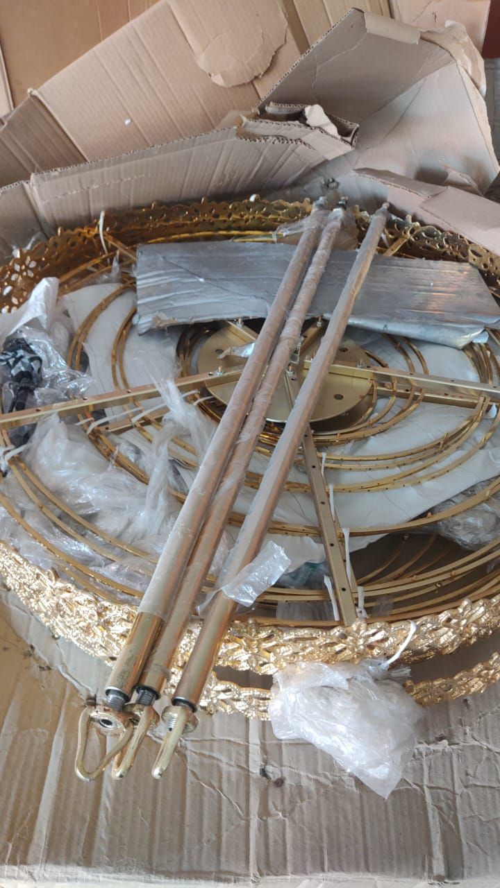
Box with three disassembled chandeliers
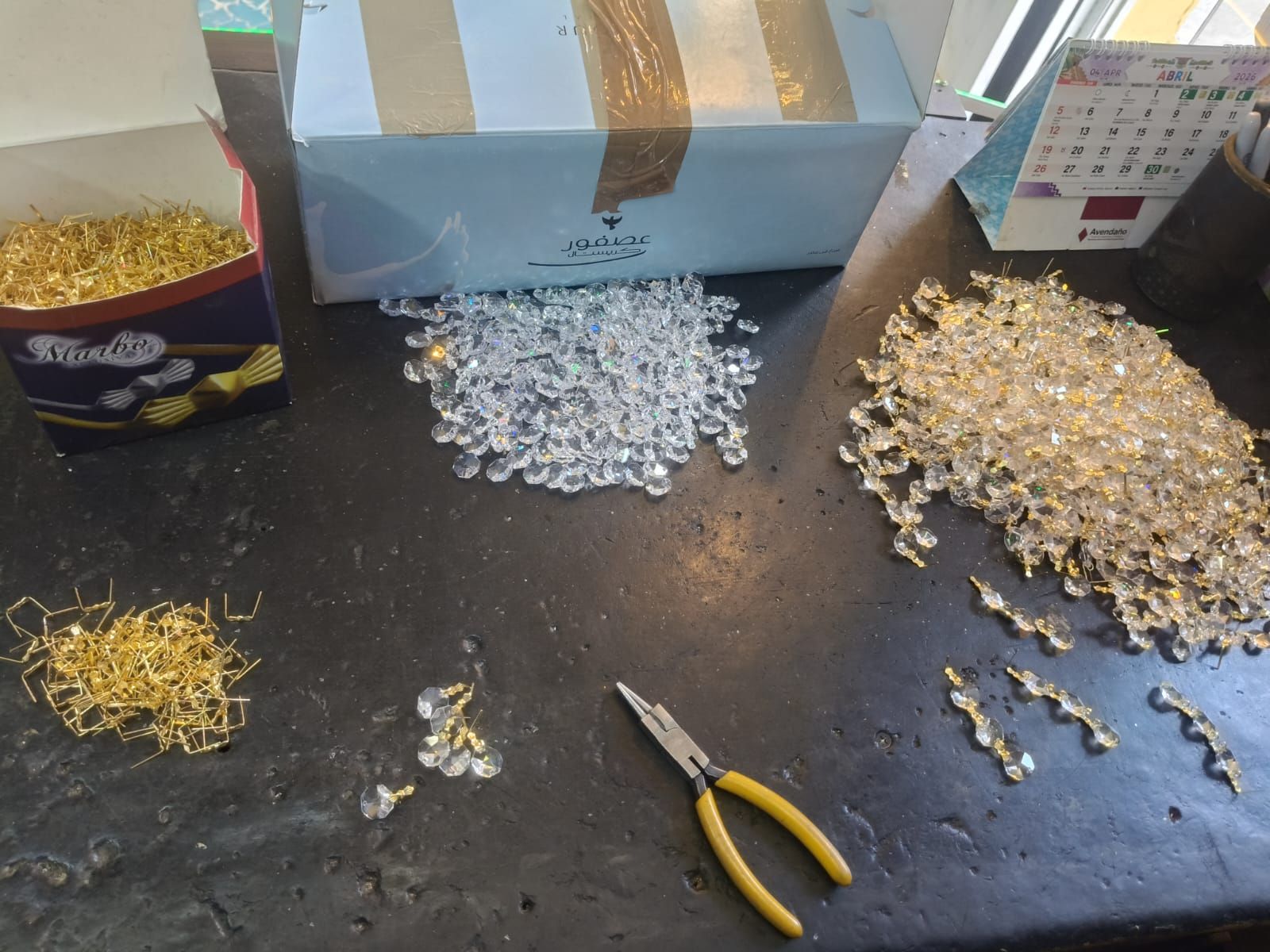
Step 2: Assembly of Cut Crystals
This is the process that my machine will automate. As shown in the carousel above, the cut crystals must be assembled using staples with the help of yellow pliers (shown in the image).
- Time investment: To dress a single Imperial Chandelier, approximately 3,500 previously assembled cut crystals — arranged in strips of different sizes — are required. Translated into time, this is one full week of work for assembly alone.
- Summary: When many orders for this chandelier arrive during peak seasons, it translates into CHAOS. Because of the chandelier's dimensions, it is not possible for us to store fully finished chandeliers.
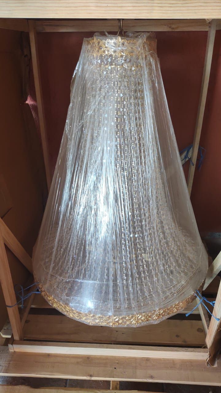
Step 3: Assembly / Dressing the Chandelier
Once all the cut crystal strips are ready, they need to be assembled onto the chandelier. This translates to a full day of work.

Step 5: Packaging
To transport the chandelier it is necessary to mount it on a wooden structure and package it to protect the chandelier.
Design & Planning
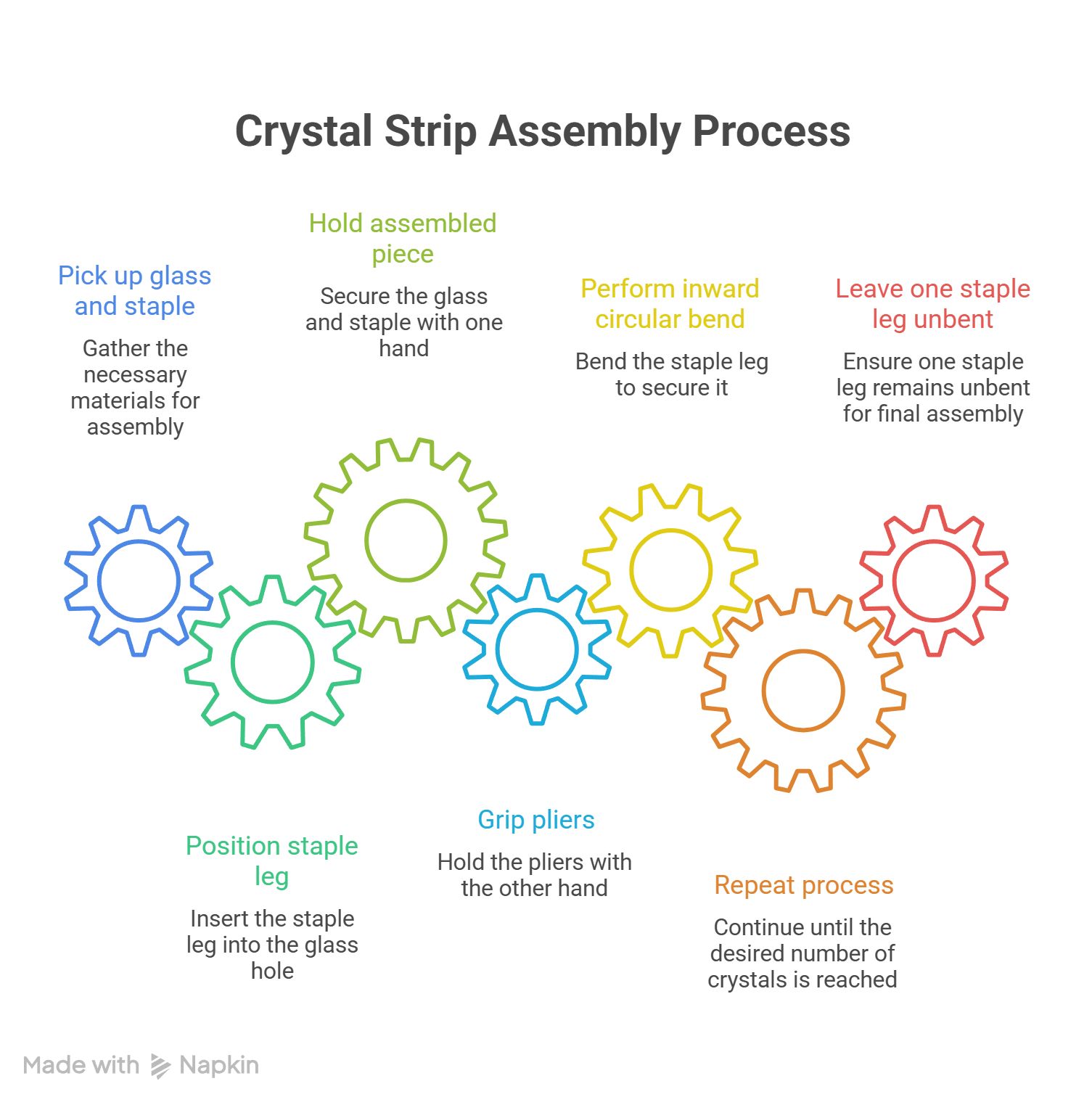
Assembly Process
- Take a piece of cut crystal and a staple.
- Position the staple leg inside one of the two holes that the cut crystal piece has.
- With one hand, hold the assembled piece, while with the other, grab the pliers.
- Make a circular inward bend toward the cut crystal to secure the staple to the crystal.
- Repeat the process until a strip with the desired number of cut crystals is formed.
- On one of the two ends of the cut crystal strip, one staple leg must be left unbent so that it can be assembled onto the chandelier body.
In Summary…
How the Machine Will Work
The machine will be composed of multiple parts because it is a production process.
Objective: Collect the raw material (cut crystals and staples), organize it, and transport it to the next step.
For this first part, two circular containers will be used for collection and organization; they will rotate by means of a gear system. These will contain the raw material: cut crystals and staples.
Through a randomness system, they will fall onto rails, which will mechanically arrange them in the correct orientation.
Idea for the Staples
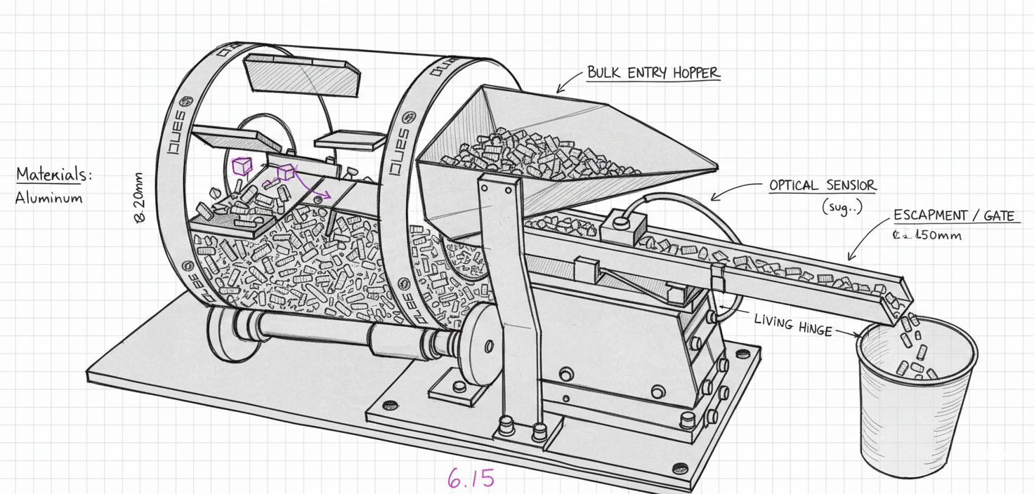
I based my idea on the following screw-sorting system:
The idea is to use the same rotating system so that the staples fall onto a conveyor belt designed like hollow walls, which will become increasingly narrower as the conveyor advances. This is to ensure all staples end up at the same opening angle.
I already have the base structure of the container, which is documented in Week 3 — Laser & Vinyl Cutting:
Daniela Barranco – Week 03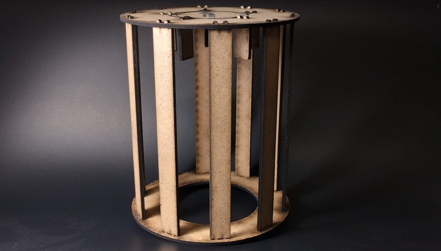
This is planned to be done using two conveyor belts where, through a crimping process, both pieces fit together.
The idea can be seen in the following YouTube video, adapted so that the staples are used instead of screws:
Additionally, in this process, a camera will keep count of the number of assembled cut crystals. The production process of this circuit for the camera can be seen in my Input Devices week:
Daniela Barranco – Week 09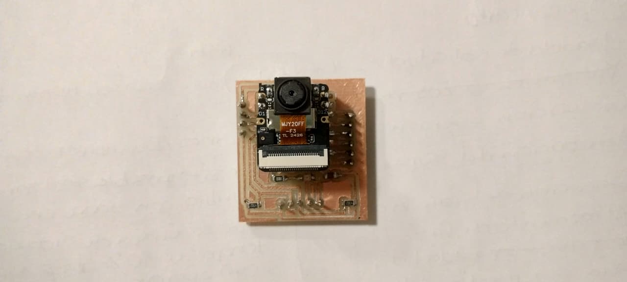
To secure the staples to the cut crystals, I intend to replace the process previously done manually with pliers by means of a mold that will have a predetermined shape to bend the staple legs.
System Integration Summary
The documentation for the system integration of my project is distributed across several weeks of Fab Academy. The following table links each week to its specific contribution to the final project:
| Week | Contribution to the Final Project |
|---|---|
| Week 03 | Staple dispenser: laser-cut base container. Original idea, staple-by-staple dispenser system. |
| Week 12 |
Electronic design: schematic and PCB in KiCad. The other part of the board (with the Raspberry Pi Pico) is documented on the page of Joseph Alavez Jaimes — Week 12, with whom I teamed up during the PCB week and who helped me build the other part of the modular board. |
| Week 09 | Input Devices: circuit with a camera for counting assembled crystals. |
| Week 10 | Output Devices: PCB for controlling two NEMA 17 motors with DRV8825 drivers (explanation of how these stepper motors and drivers are used). |
| Week 14 | Interface: MQTT dashboard for configuring and monitoring the assembly line. |
| Week 15 | System Integration: integration of all the subsystems above. |
Implementation Timeline
To Do
- Conveyor belts / rails (mechanism).
- System for correctly sorting and positioning the staples and cut crystals.
- Assembly system.
- Bending system / mold to secure the staple.
- Piece-count detection with camera / image detection (optional).
- Send instruction on the number of pieces required (Communications).
- Final output system.
- Structure.
- Prepare the presentation.
- Present.
April
| Check | Fab Academy Task | Final Project Task | Week |
|---|---|---|---|
| ✔ | Molding and Casting | System for correctly sorting and positioning the staples and cut crystals; bending system. | 20 – 26 |
| ✘ | Interface and Application Programming | Conveyor belts; mechanical assembly system. | 27 – 3 May |
May
| Check | Fab Academy Task | Final Project Task | Week |
|---|---|---|---|
| ✘ | System Integration | Assembly system programming; piece-count detection with camera / image detection (optional). | 4 – 10 |
| ✘ | Wildcard Week | Send instruction on the number of pieces required (Communications); final output system. | 11 – 17 |
| ✘ | Applications and Implications, Project Development | Structure. | 18 – 24 |
| ✘ | Invention, Intellectual Property, and Income | Buffer week in case of setbacks; finish pending documentation. | 25 – 31 |
June
| Check | Fab Academy Task | Final Project Task | Week |
|---|---|---|---|
| ✘ | — | Prepare presentation; record video and finish final details. | 1 – 7 |
| ✘ | Final Project Presentations | Final presentation. | June 8 |
Final Project Q&A
This section answers the key documentation questions required for the Fab Academy final project evaluation, summarizing the development, results, and implications of the Automated Crystal Assembly System built for Lámparas y Candiles de Oaxaca.
What does it do?
The machine automates the assembly of cut crystal strips used to dress Imperial Chandeliers. Normally, linking each crystal to the next using aluminum staples is a fully manual process that takes approximately one full week per chandelier (around 3,500 crystals per unit). The machine replaces this process by mechanically organizing the crystals and staples, assembling them via conveyor belts, and bending the staple legs to secure each crystal — producing finished crystal strips ready to be mounted on the chandelier frame.
Who's done what beforehand?
No directly comparable open-source or academic precedent was found for this specific process. Industrial crystal assembly systems do exist, but they are proprietary and undocumented — used by large-scale manufacturers under confidential processes. The reference systems that informed the design approach were:
- Drum feeder and vibratory linear chute systems (for orienting small parts like screws and staples).
- Rotating cap-sorter systems (for orienting flat parts with holes, adapted for the cut crystals).
- Crimping conveyor belt systems (for the assembly step, adapted to use staples instead of screws).
These references are documented and linked in the Final Project page under the Design & Planning section.
What did you design?
The following elements were designed as part of this project:
- Crystal organizer — 3D-modeled component to receive and orient the cut crystals before the assembly step.
- Staple organizer — 3D-modeled component to orient the aluminum staples at the correct angle.
- Staple dispenser base container — laser-cut in MDF (documented in Week 03).
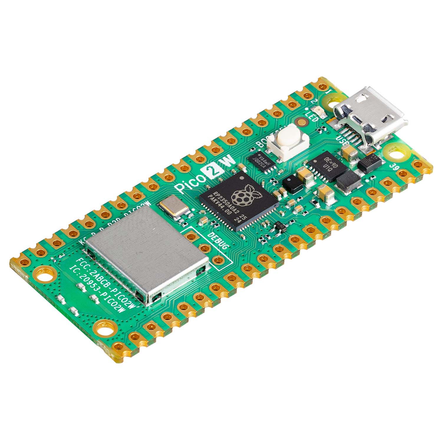
- PCB for stepper motor control — schematic and board designed in KiCad to drive 4 NEMA 17 motors with DRV8825 drivers from a Raspberry Pi Pico 2W (documented in Week 12).
- Crystal counting circuit — input device circuit using a camera for counting assembled crystals (documented in Week 09).
- MQTT dashboard — browser-based interface to configure the number of crystals and strips required, and to monitor progress in real time (documented in Week 14).
- MDF enclosure box — structural packaging designed in SolidWorks to house all electronics and mechanics, with the company logo laser-engraved.
- System integration workflow — end-to-end diagram connecting all subsystems from raw material input to finished crystal strip output.
What sources did you use?
- YouTube reference videos for the drum feeder, cap-sorter, and crimping conveyor belt systems (linked in the Final Project page).
- Fab Academy weekly documentation from previous cohorts as general reference.
- Datasheets for the DRV8825 stepper motor driver and NEMA 17 motors.
- HiveMQ documentation for MQTT broker configuration.
- Raspberry Pi Pico 2W official documentation and pinout.
- SolidWorks and KiCad official documentation.
What materials and components were used? Where did they come from? How much did they cost?
All components were provided by the Fab Academy lab at IBERO Puebla. The following table summarizes the materials and known costs:
Note: USD prices are calculated using the exchange rate of $17.56 MXN per USD, which was the rate on June 23, 2026.
Conveyor Belt & Organizers
| Material | Quantity | Unit Cost (MXN) | Total Cost (MXN) | Total Cost (USD) | Where to Find It |
|---|---|---|---|---|---|
| Stepper motor (NEMA 17) | 3 | $250 | $750 | $42.71 | Electronics store |
| Driver DRV8825 (stepper motor controller) | 3 | $60 | $180 | $10.25 | Electronics store |
| 3D PLA filament | 1 kg | $300 | $300 | $17.08 | Amazon |
| Rubber strip (1.8 mm × 3.5 mm) | 3 m | $33 | $99 | $5.64 | Rubber supply store |
| Raspberry Pi Pico 2W | 1 | $300 | $300 | $17.08 | Amazon / Electronics store |
| External power supply 12V 5A | 1 | $185 | $185 | $10.53 | Amazon |
| Plug and electrician's cable | 1 plug + 1.5 m cable | $50 | $50 | $2.85 | Electronics store |
| Copper plates (PCB) | 3 | $30 | $90 | $5.12 | Fab Academy materials |
| Hexagonal bolt M8 | 2 | $5 | $10 | $0.57 | Hardware store |
| M8 nut | 8 | $1 | $8 | $0.46 | Hardware store |
| Washer | 10 | $1 | $10 | $0.57 | Hardware store |
| Self-tapping screw 8 × 3/8 combo head | 30 | $0.50 | $15 | $0.85 | Hardware store |
| 3/8 washer | 70 | $0.50 | $35 | $1.99 | Hardware store |
| Terminal block (clema) | 1 | $20 | $20 | $1.14 | Hardware store |
Packaging Box
| Material | Quantity | Unit Cost (MXN) | Total Cost (MXN) | Total Cost (USD) | Where to Find It |
|---|---|---|---|---|---|
| MDF sheet | 1 | $70 | $70 | $3.98 | Hardware store |
| Acrylic sheet (50 × 50 cm) | 1 | $350 | $350 | $19.93 | Hardware store |
| Hinge | 2 | $30 | $60 | $3.42 | Hardware store |
Approximate total project cost: $2,532 MXN / $144.19 USD
What parts and systems were made? What processes were used?
| Part / System | Process Used | Documented In |
|---|---|---|
| Staple dispenser base container | Laser cutting (MDF) | Week 03 |
| Crystal counting circuit | PCB fabrication, input device programming | Week 09 |
| Stepper motor control PCB | KiCad schematic & PCB design, CNC milling, soldering | Week 12 |
| Crystal and staple organizers | 3D modeling (SolidWorks), 3D printing | Week 15 |
| MQTT dashboard | Interface programming (Node-RED / web dashboard) | Week 14 |
| Conveyor belt system | Mechanical assembly, stepper motor firmware (Arduino IDE / Pico 2W) | Week 10 |
| MDF enclosure box | 3D modeling (SolidWorks), laser cutting, logo engraving (Inkscape) | Week 15 |
What questions were answered?
- Is it feasible to automate the crystal assembly process for a small family business using digitally fabricated tools? Yes.
- Can a Raspberry Pi Pico 2W control multiple NEMA 17 stepper motors simultaneously via DRV8825 drivers? Yes, as demonstrated in Weeks 10 and 12.
- Can an MQTT dashboard replace a physical control panel for this type of machine? Yes — the dashboard allows configuring and monitoring the assembly line from any browser-connected device.
- Can the bending process be mechanized without a fully custom industrial die? Partially — a mold was developed, but the process required significant adjustment.
What worked? What didn't?
✔ What worked:
- The conveyor belt system functioned correctly, successfully transporting pieces through the assembly stages.
- The bending system was achieved — the staple legs were bent to secure the crystals, even though it required significant iteration.
- The MQTT dashboard worked as the machine's operating interface.
- The PCB for stepper motor control operated as expected.
✘ What didn't work as expected:
- Correctly orienting the cut crystals on the conveyor belt was challenging — the crystals did not always fall into the correct position automatically.
- The bending system, while functional, was more difficult to implement than anticipated and required multiple adjustments to achieve a consistent bend.
- The automatic staple orientation system (original drum-feeder concept from Week 03) was replaced by a manual system due to mechanical complexity and time constraints.
How was it evaluated?
The machine was evaluated functionally: each subsystem was tested independently before integration, and then the complete system was run to verify that crystals and staples were correctly assembled into strips. A formal time study comparing manual assembly versus automated assembly is planned as future work — once a more refined version of the machine is developed — to quantify the productivity gains for Lámparas y Candiles de Oaxaca.
What are the implications?
This project demonstrates that digital fabrication tools available in a Fab Lab are sufficient to prototype automation solutions for small and medium-sized family businesses that would otherwise have no access to industrial machinery. The specific implications for Lámparas y Candiles de Oaxaca are:
- Productivity: Reducing crystal strip assembly time from one week to a fraction of that — enabling the business to respond to peak-season demand without the current bottleneck.
- Cost reduction: Making it viable to buy unassembled chandeliers from the supplier (at one-fifth of the fully assembled price) while assembling them in-house at a much lower labor cost.
- Scalability: The modular design of the machine (separate subsystems for feeding, assembly, and bending) allows individual stages to be improved or replaced independently as the business grows.
- Broader impact: The same approach — low-cost digitally fabricated automation — could be replicated by other small artisan and manufacturing businesses in Oaxaca and across Mexico facing similar manual assembly bottlenecks.
Construction of the Machine
3D Design
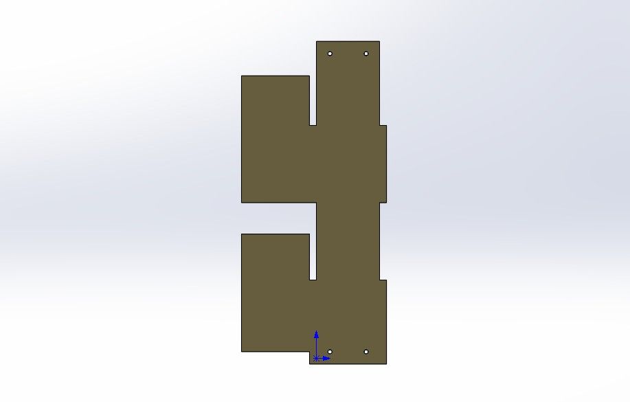
Machine Parts
Machine Parts
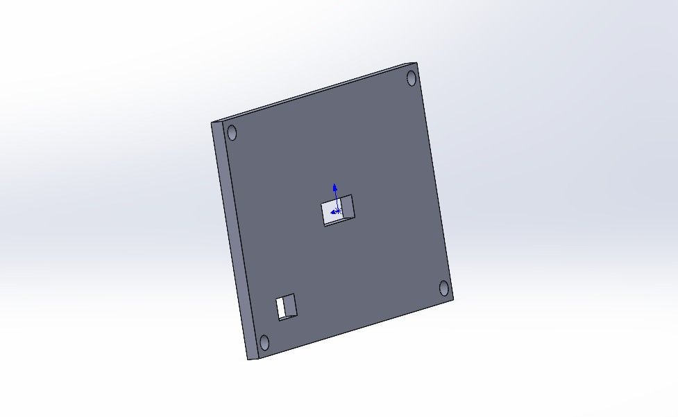
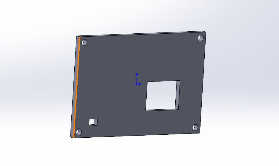
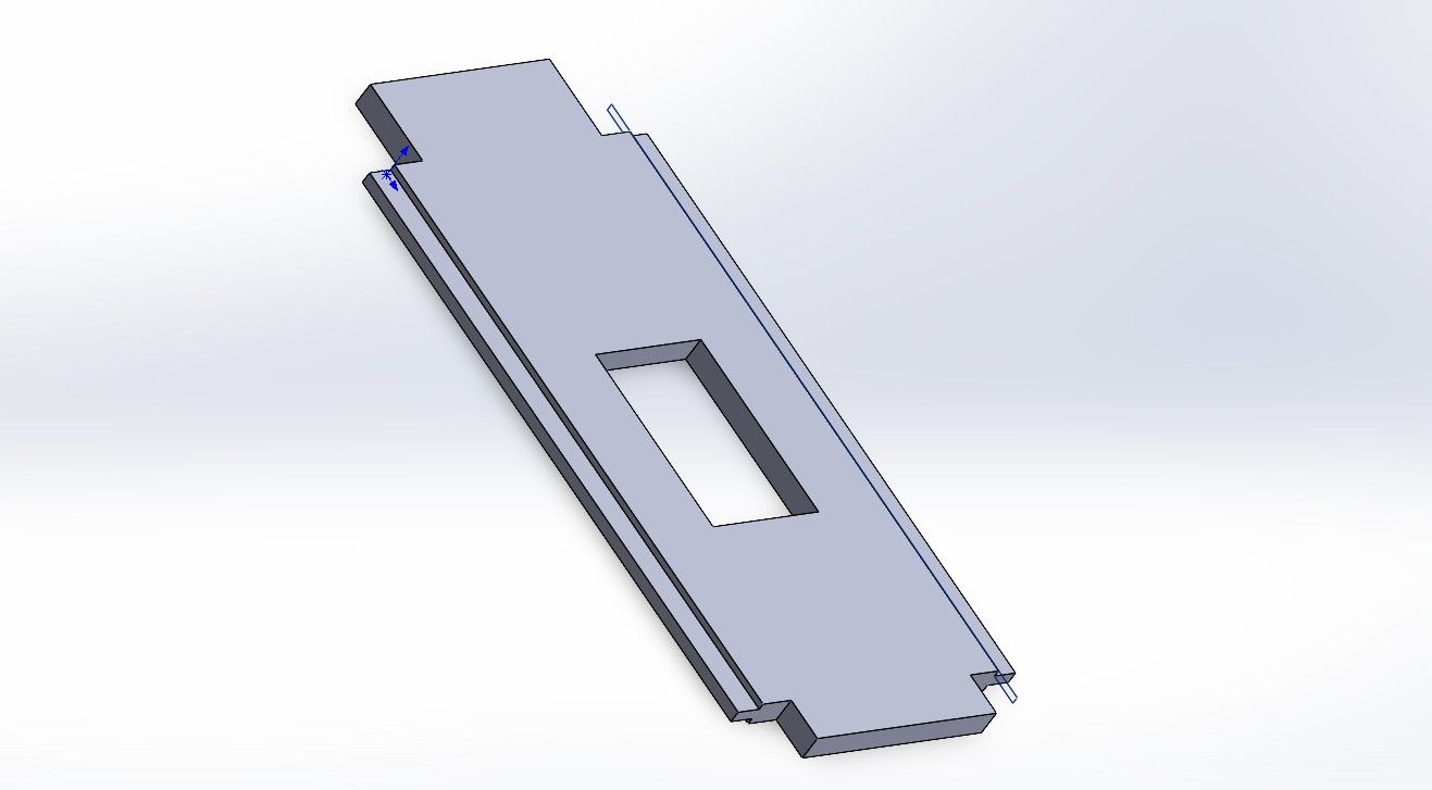
1. Side Wall (Pared Lateral) — This is one of the two walls that encloses the machine, and on which the Fab Academy logo was engraved.
2. Support (Soporte) — This small piece goes in the inner corners of the MDF parts and was fastened with M3 screws, nuts, and washers. Its function is to provide greater stability and strength to the structure.

3. Sliding Stopper — This piece is fastened with a screw, nut, and washer. Its function is to manually adjust the ceiling that will hold the crystals and keep the conveyor belt level.
4. Bottom Wall — This is the floor of the machine and helps each wall fit into place.
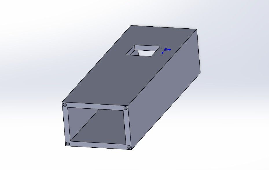
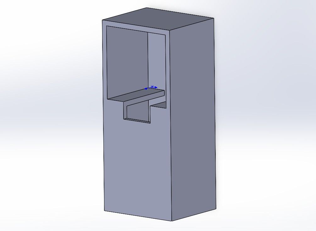
5. Container Box (Caja Contenedora) — This box is for System Integration — it contains the electronic boards, the power supply, and the cables.
6. Slide — This is one of the most important pieces, as it helps remove the assembled cut crystals from the conveyor belt before it loops back around.
7. Front Cover — This is one of the two lids of the container box, secured with M3 screws. The central opening allows the physical emergency stop button to protrude through it.
8. Back Cover — This is the rear lid, through whose hole the power supply cable passes.
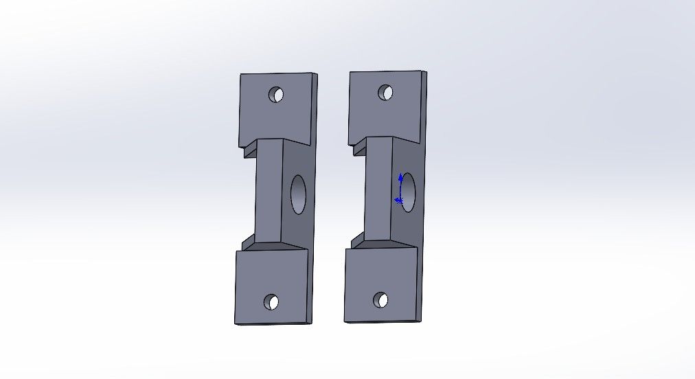
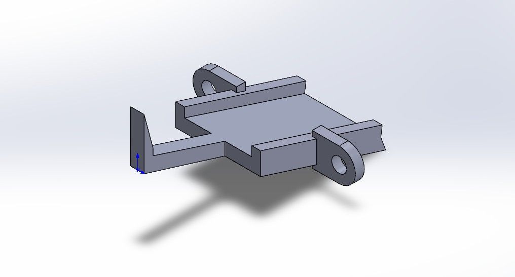
9. Screw Support — These supports are attached with M3 screws and provide support for the large screws that tension the machine. Through the nuts, the screws for the conveyor belt can also be adjusted.
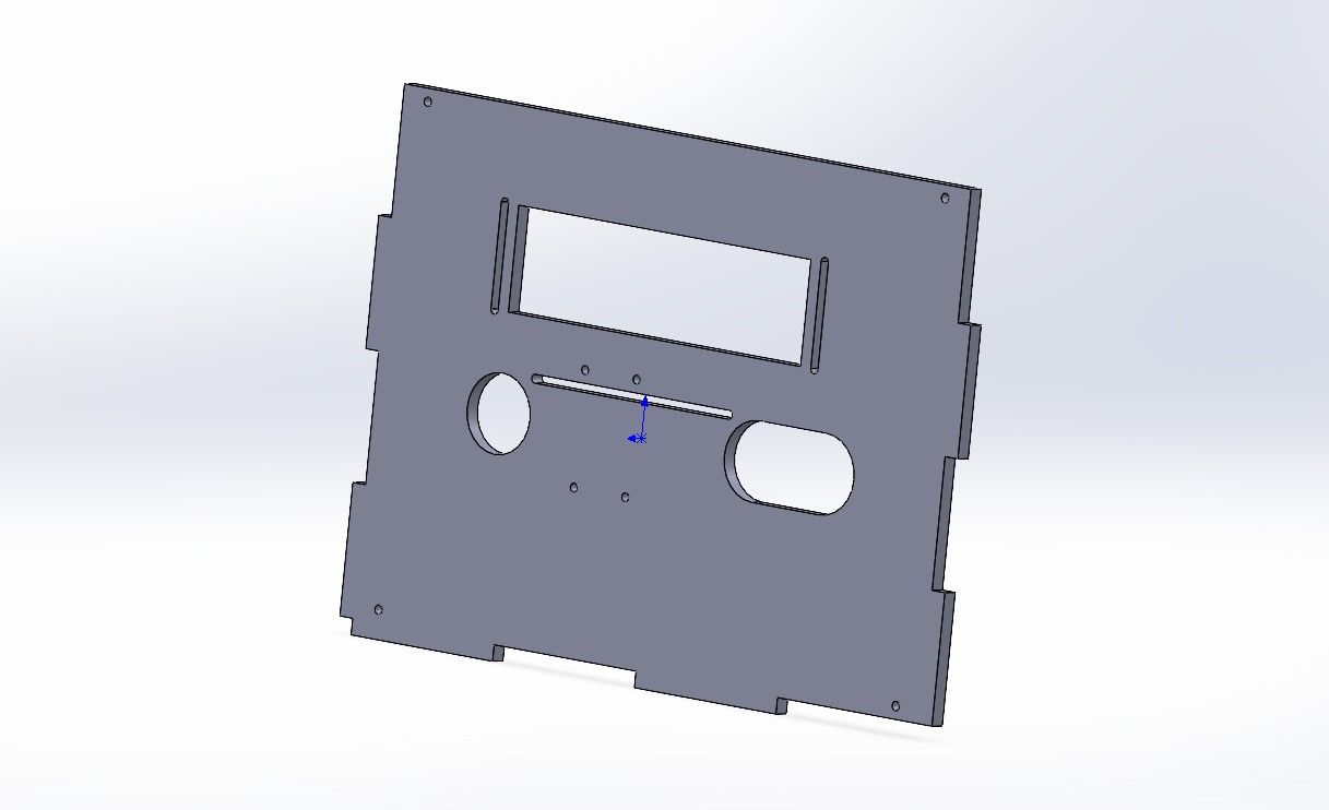
10. Main Wall — These are the main walls to which everything else is attached with screws, and which provide support for the main system.
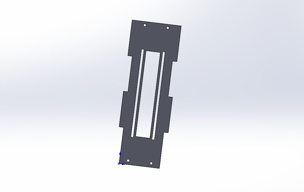
11. Side Wall with Holes — This is the other side wall where the slide will be manually adjusted.
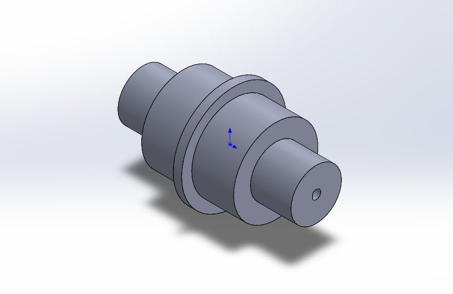
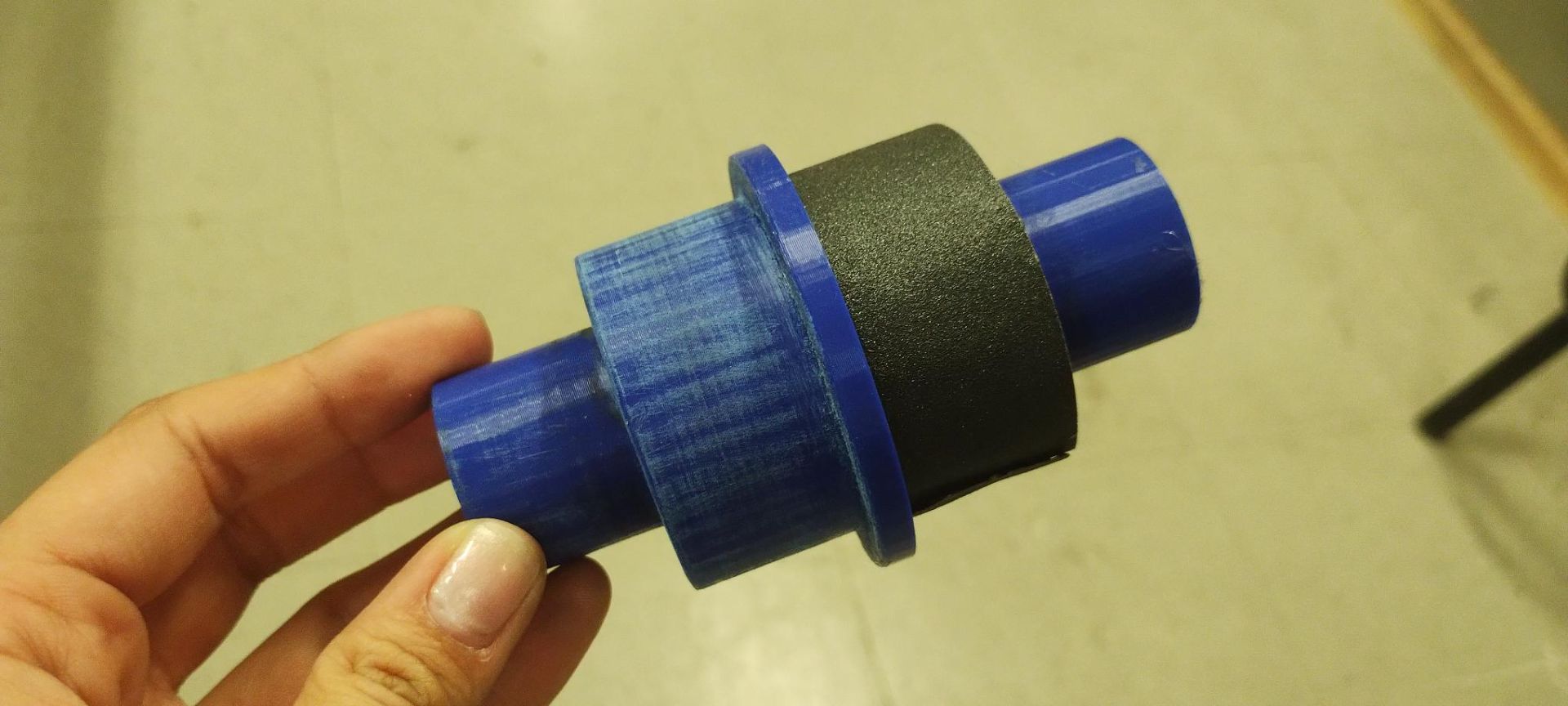
12. Roller — These allow the conveyor belt to rotate and are also connected to the stepper motor.
13. Ceiling — This is the roof of the machine and prevents the crystals from falling out of the conveyor belt molds as they pass through the bending system.
14. Stepper Motor Mount — This is the base where the stepper motor will be placed.
Conveyor Belt
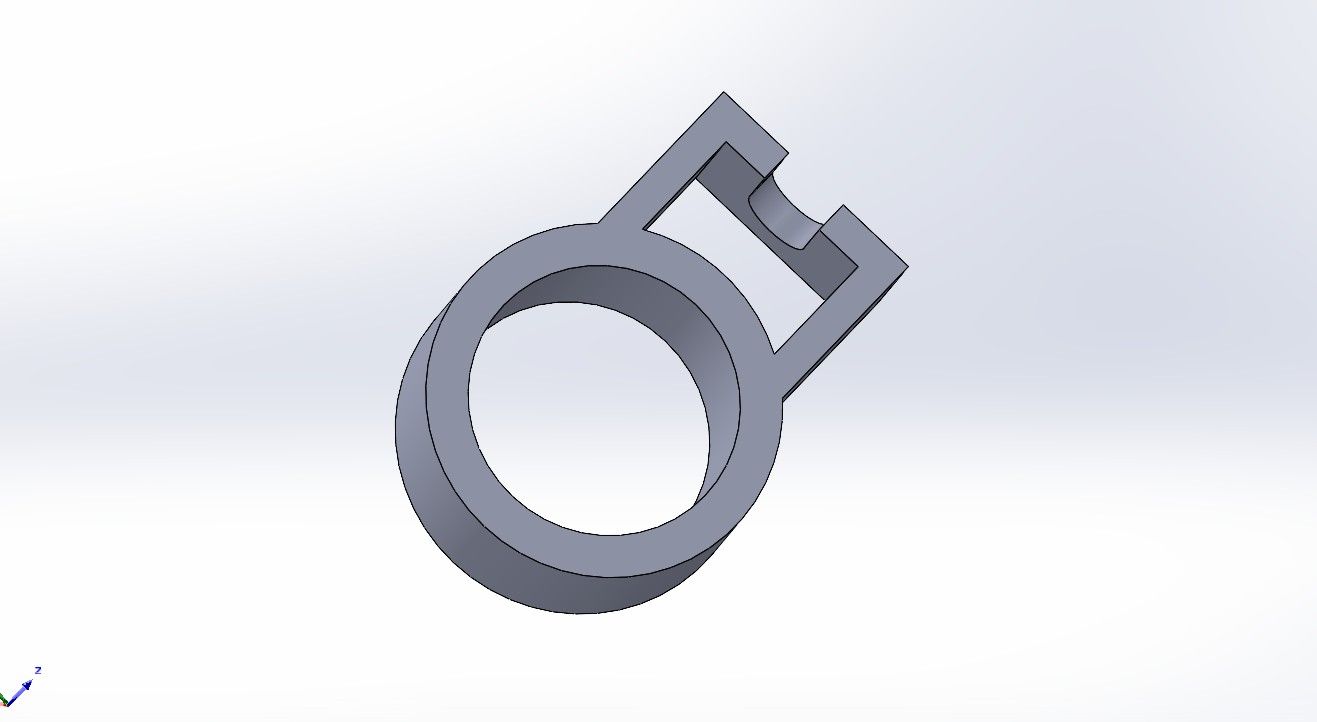
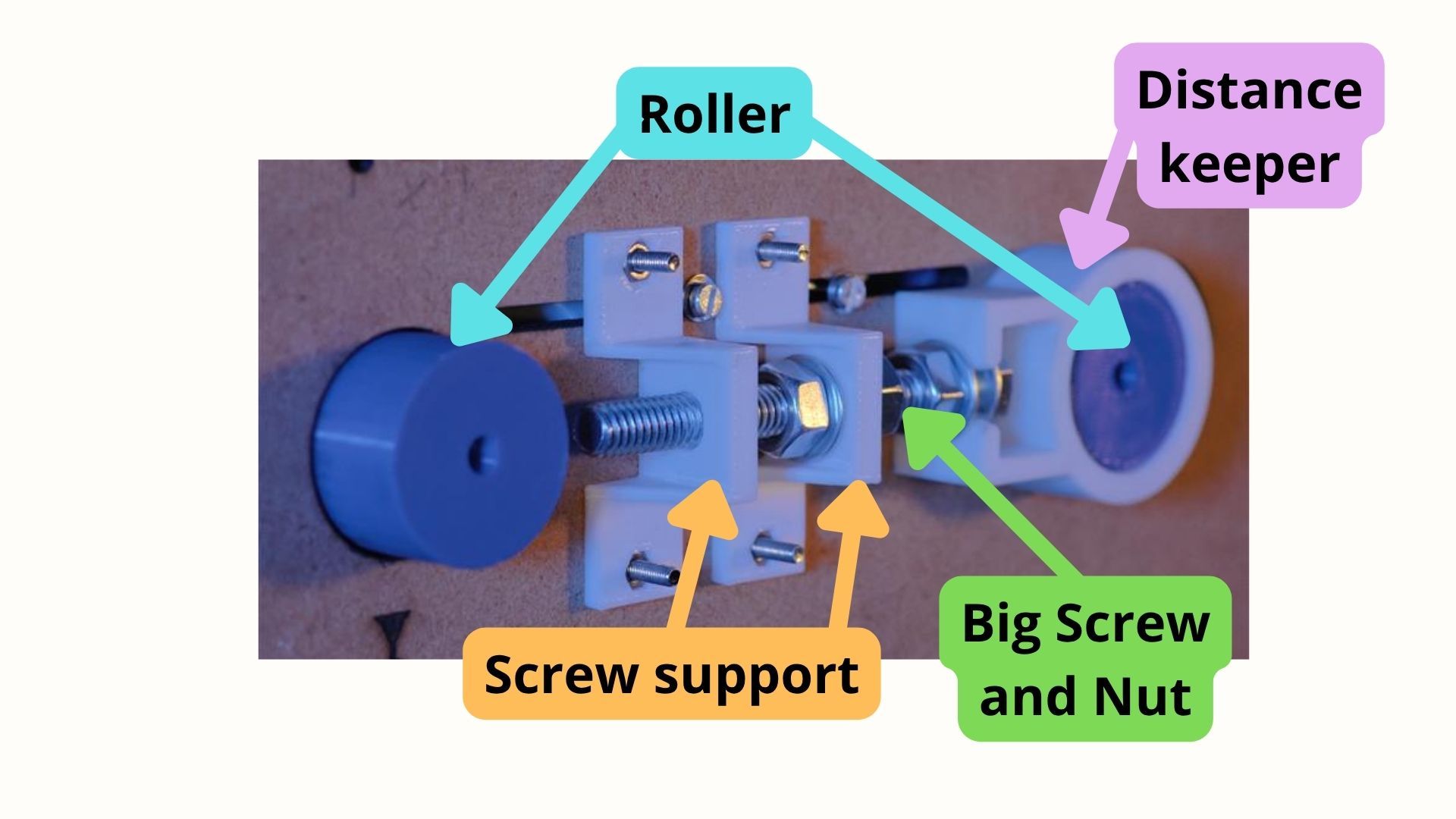
15. Distance Keeper — This piece sits on the outside of the Roller and adjusts the distance to tension the belt.
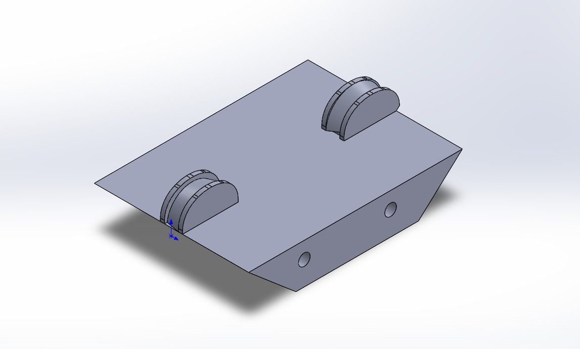
16. Bending Piece (Doblador) — This is the most important piece of the mechanism and sits right in the center — it is the one that bends the staples.
Additive
The parts from the list above that were 3D printed were:
- 02_supports
- 03_sliding stopper
- 05_container box
- 06_Slide
- 07_Lid
- 08_back cover
- 09_screw support
- 12_Roller
- 13_Ceiling
- 14_stepper motor mount
- 15_bending
3D printer in use
Note: For the "12_Roller" piece, it was necessary to sand it with 220-grit sandpaper and then hot-glue a piece of 220-grit sandpaper onto it to increase the contact surface. This is because this piece is responsible for making the rubber conveyor belt rotate.
Subtractive
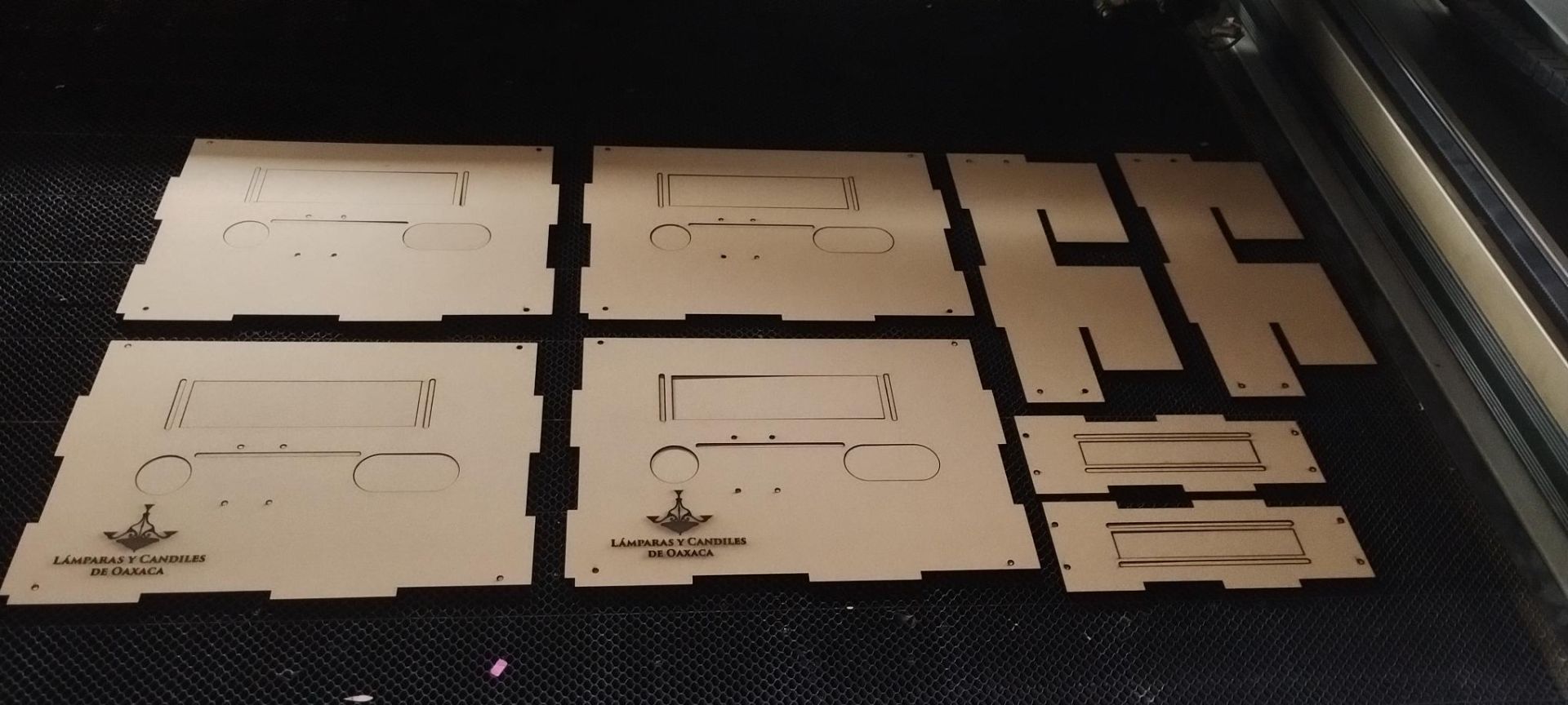
Laser Cutting
The parts to be laser cut are the following:
- 01_side wall
- 04_bottom wall
- 10_main wall
- 11_side wall with holes
Note: In order to make the structure more solid and strong, I preferred all walls to be 6 mm thick (this was also considered in the initial design). However, our node only had 3 mm MDF available, so:
- I cut each piece twice.
- I sanded one of the two surfaces of each piece with medium-grit sandpaper (to make the surface more porous).
- Using 850 white glue, I bonded each piece to its matching counterpart to double the wall thickness.
Cutting parameters:
- Max. Power (%): 40
- Min. Power (%): 35
- Work Speed (mm/s): 10
Vectorizing and Engraving
The company logo and the Fab Academy logo were also engraved. For this, I used Inkscape.
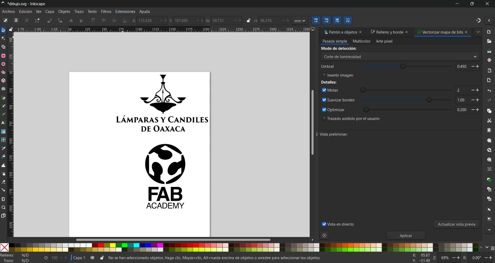
The explanation of the vectorizing process is in Week 2 of Fab Academy: (Daniela Barranco - Week 02)
The logos were subsequently engraved using the laser machine as well.
Engraving parameters:
- Max. Power (%): 15
- Min. Power (%): 10
- Work Speed (mm/s): 150
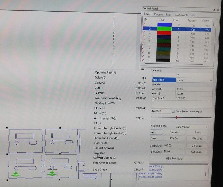
Notes on the entire laser cutting process:
- Operation order: Engraving must be done first, followed by cutting.
- Engraving: It is important to select the "Fill" button at 100%. Additionally, before sending to cut, all components to be cut or engraved must be selected, and it is essential to click the "Group" button.
Gluing the Pieces
- As mentioned earlier, on the side to be glued, lightly sand the surface of the piece with 220-grit sandpaper.
- Do the same with its matching counterpart.
- Then spread a thick layer of 850 white glue across the entire piece.
- Join the glued side with its matching counterpart.
- Use binder clips to clamp the two pieces together and leave them to air dry.
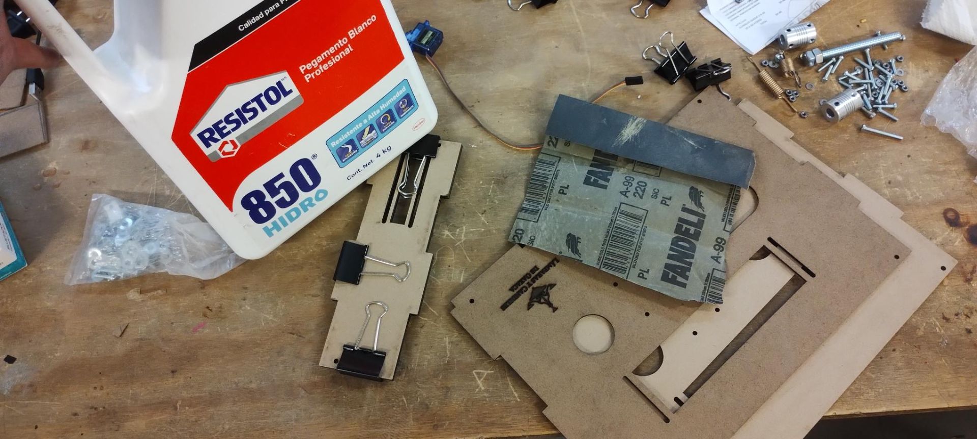
Materials needed for the gluing process
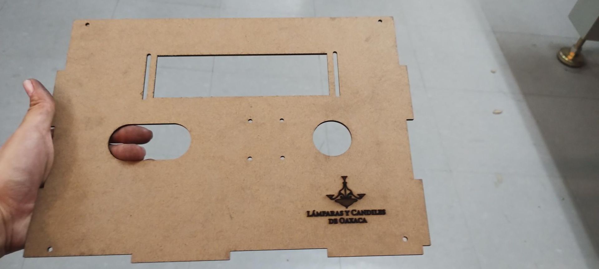
Spreading glue across the pieces
The pieces look like this once finished:
The inside of the machine looks like this:
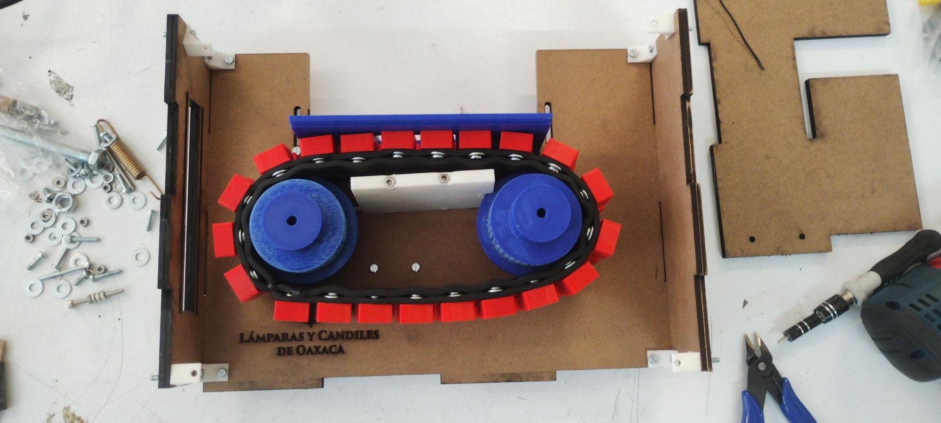
Conveyor Belt
To build the conveyor belt, a box with holes was needed to ensure equal spacing between the crystal molds.
The cut crystal molds are placed face-down in the corresponding holes of the box.
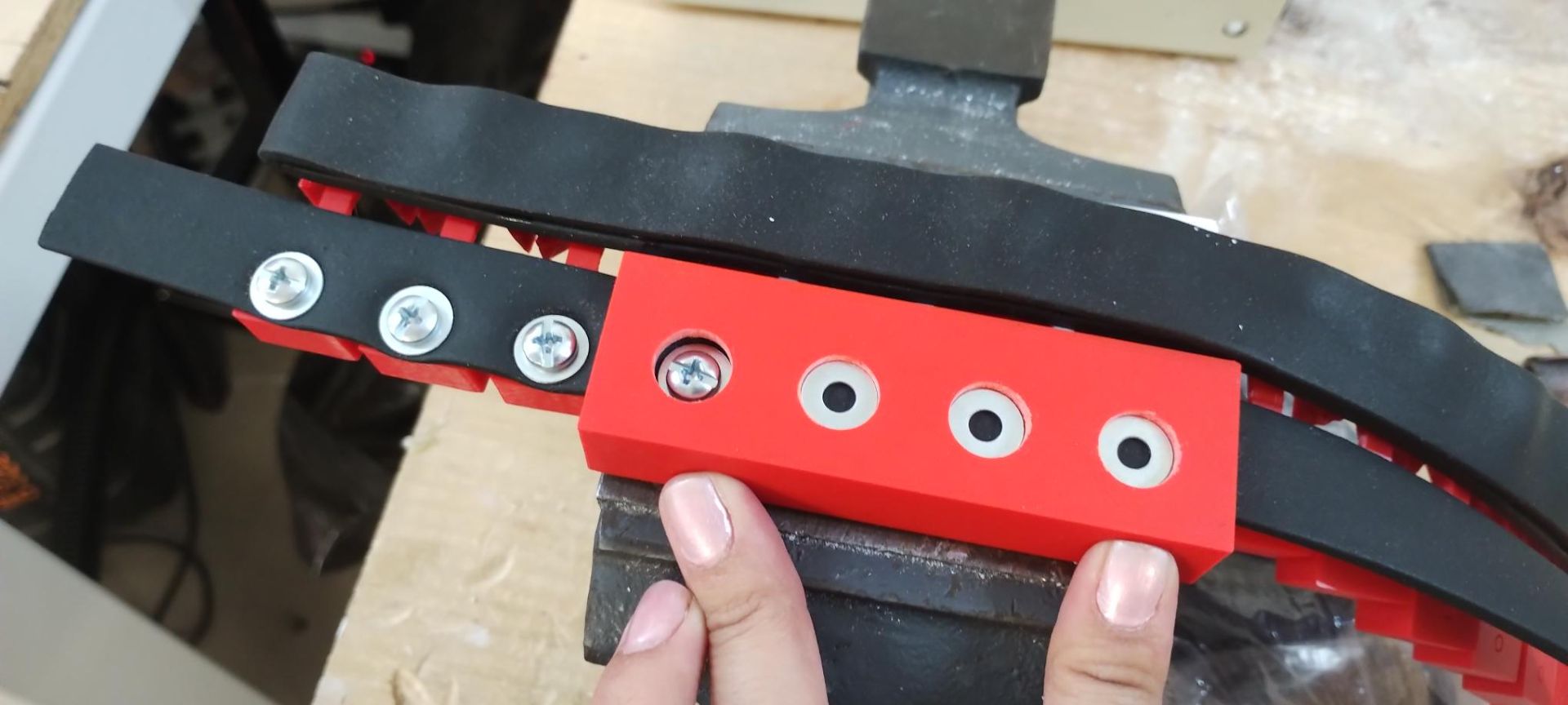
The lid is placed and the rubber band passes through the corresponding opening. Then, in the circular holes, a washer is inserted followed by an 8 x 3/8 screw, which is tightened with a screwdriver (preferably electric).
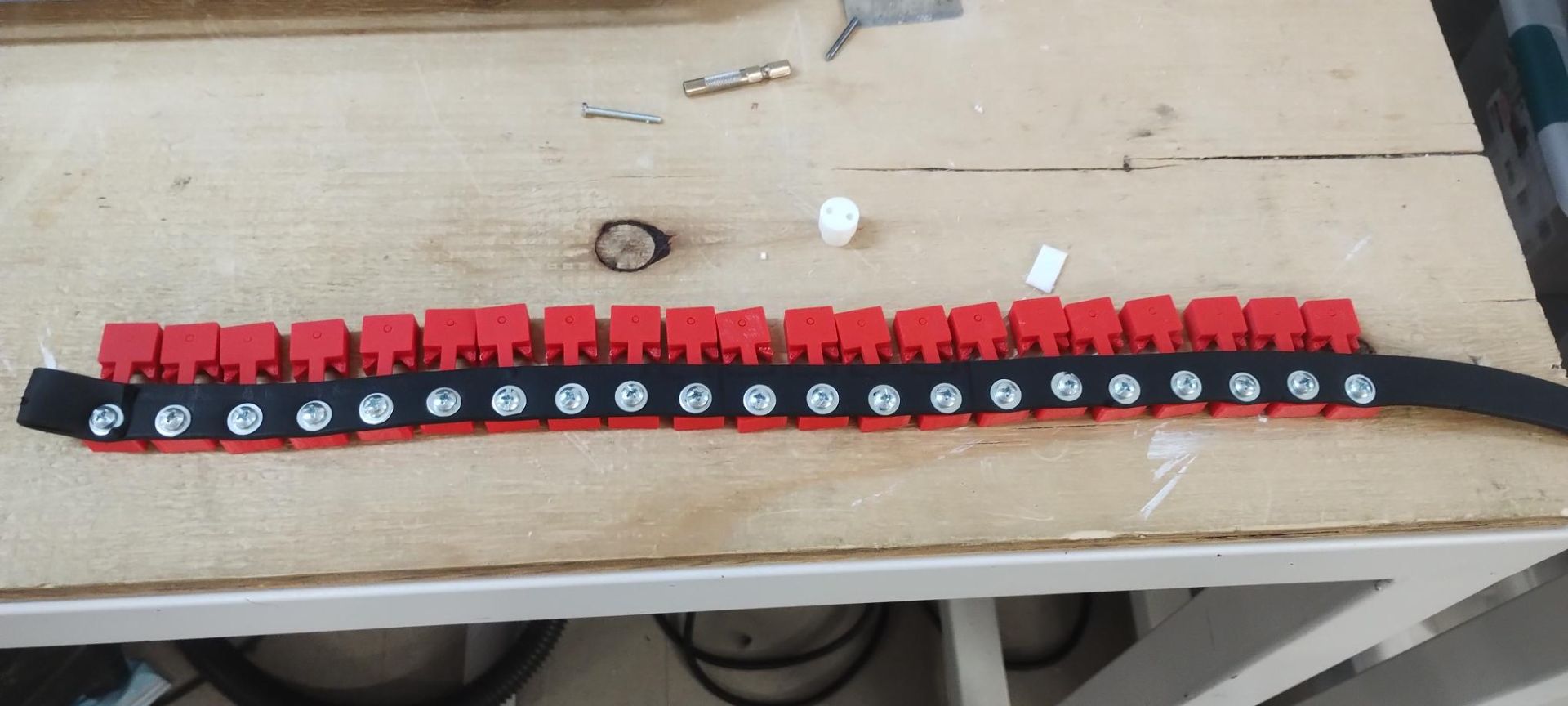
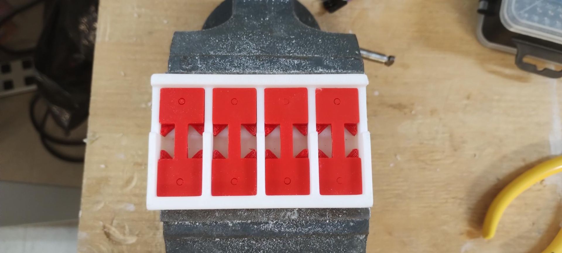
The process is repeated until all 21 red pieces are complete — these are the molds where the cut crystals will sit.
The full process looks like this:
Then, to cover the screws and washers, the rubber must be glued using Kola Loca or a similar adhesive between the rubber sections in the spaces between screws.
To make the other side, the exact same process is followed, but instead of using the full lid (the white one in the previous images), the half lid is used — in my case, printed with red filament.
Finally, both ends are joined with a plastic cable tie.
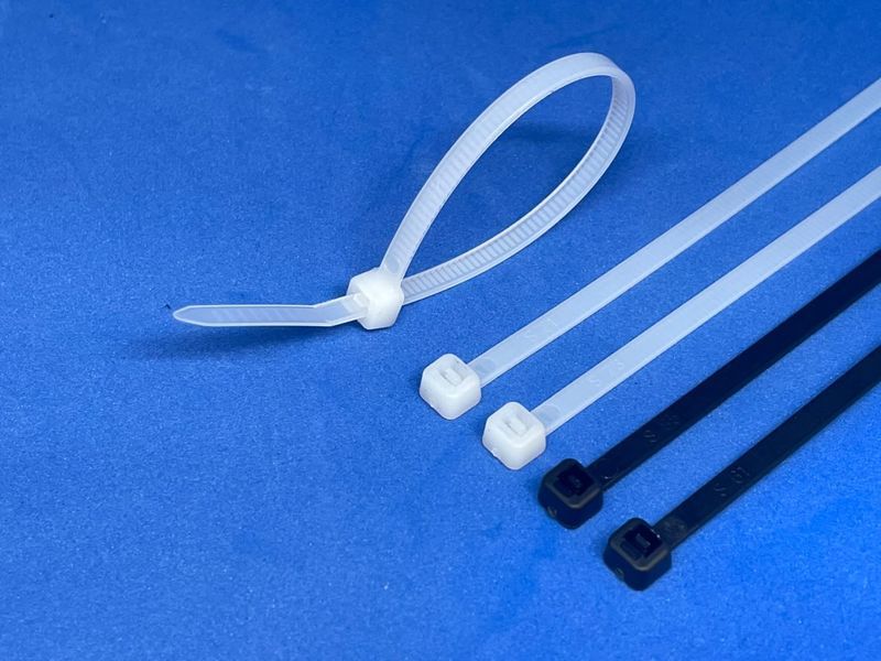
An illustration of what I mean by plastic cable ties
Belt Tensioning System
This system works by adjusting the nuts so the screw can move forward or backward depending on what is needed. This in turn moves the "Distance Keeper" piece, which is also connected at the screw head and held by a nut.
The 3D-printed pieces serve as supports for the screw and also as a stop to fix the belt distance.
Bending System
This is achieved through this piece, which mechanically performs the bend in the staples.
Piece modeled in SolidWorks
The following video is a SolidWorks simulation of how the machine works and bends the staples.
Electronics
Microcontroller: Raspberry Pi Pico 2W
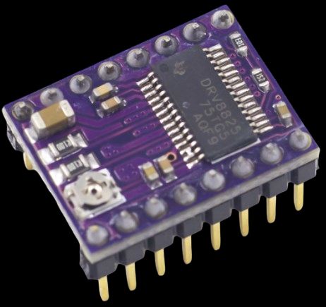
Drivers: 8825
Output
To drive the rollers, a NEMA 17 stepper motor was used.
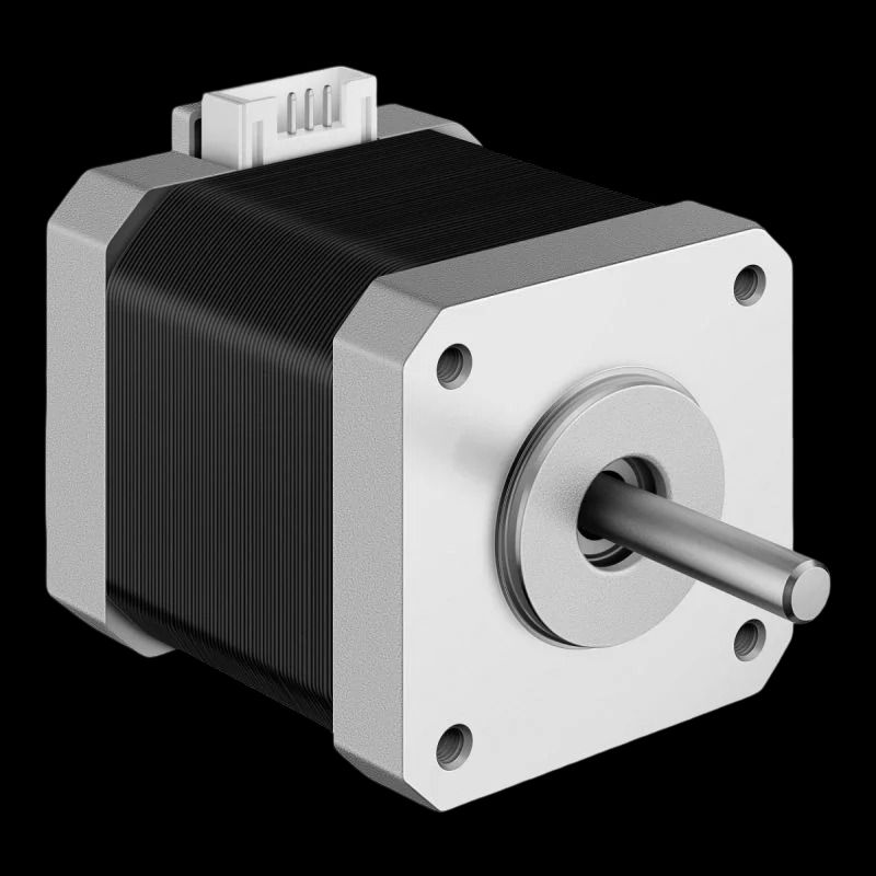
For more details on how the motors work and/or the calculations, refer to Week 12.
Daniela Barranco - Week 12Input
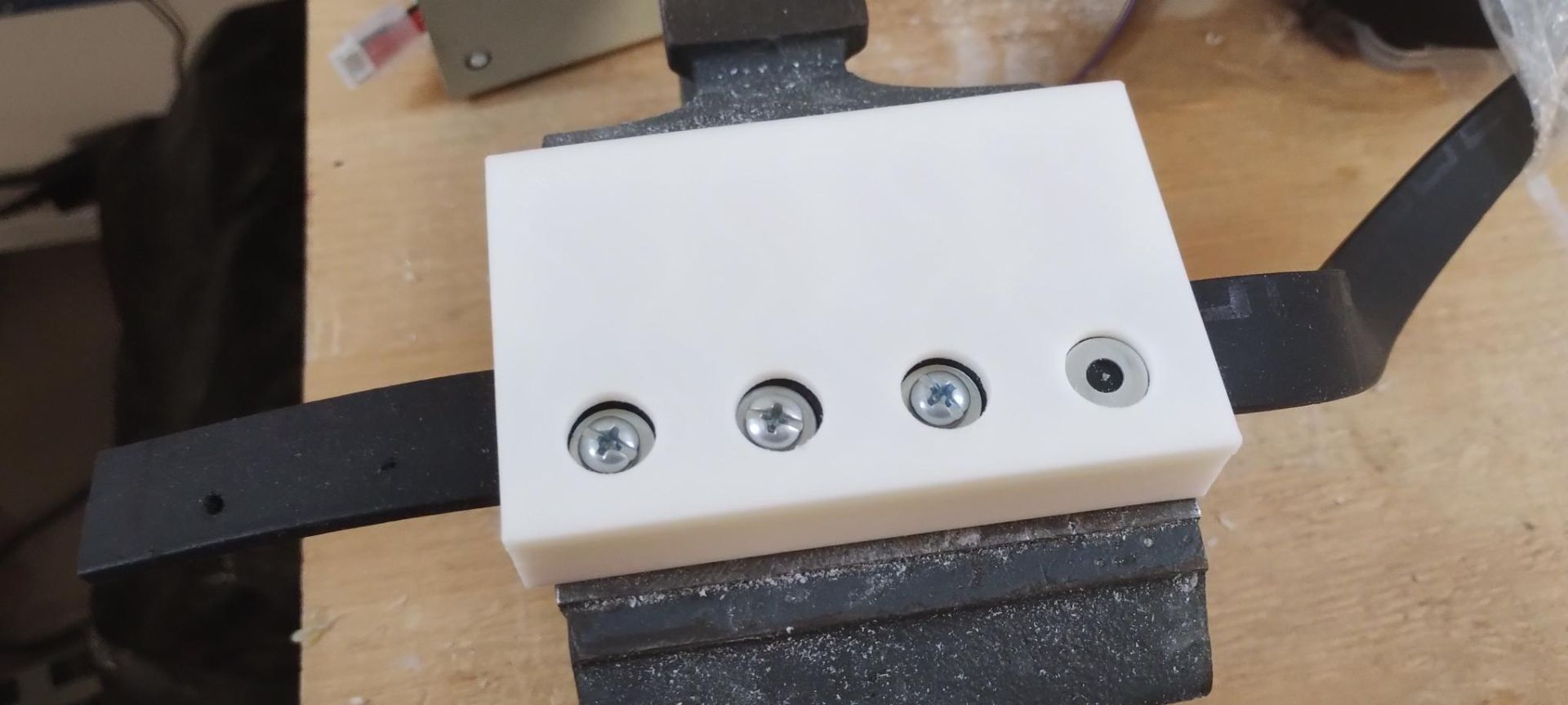
As an input, a small modular board was made with a physical emergency stop button.
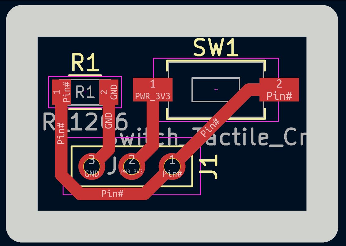
Schematic of the emergency stop button board
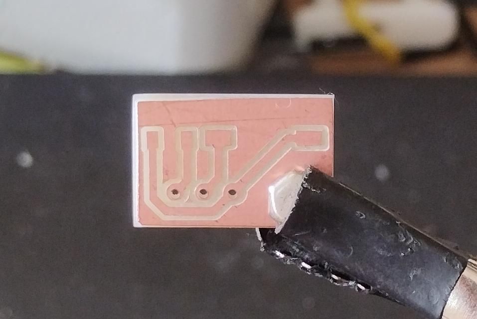
Finished board
Interfaces
To make it much more user-friendly for the company's staff to operate the machine, I developed an interface that works as a control panel. It also keeps a count of the orders generated, which can also be viewed in the Orders tab of the interface.
Real-Time Dashboard
This view has two functions: configuring a new batch and monitoring progress in real time.
Batch configuration (static part):
- The "Batch Order Placement" panel receives Crystals Per Series and Number of Series. When ADD is pressed, this is only saved in browser memory (batchConfig) and generates a temporary Batch ID — nothing is sent via MQTT yet.
- The "Order" panel asks for the Lot (batch name) and auto-fills the date. When ADD is pressed here, the configuration is published to the broker — the ESP32 receives it, the definitive Batch ID is generated, and a new row is created in the Orders table with a QUEUED status.
Real-time monitoring (dynamic part):
- The "Assembled Cut Crystals" and "Series Produced" cards display X/Y counters with progress bars.
- These values are not calculated by the interface — the interface only displays them. They are calculated and sent by the ESP32/Pico, which publishes JSON messages to the sensor topic every time it advances.
- The START button publishes the INICIAR command and changes the active order status to PROCESSING.
- The EMERGENCY STOP button publishes DETENER and marks the order as MANUAL STOP.
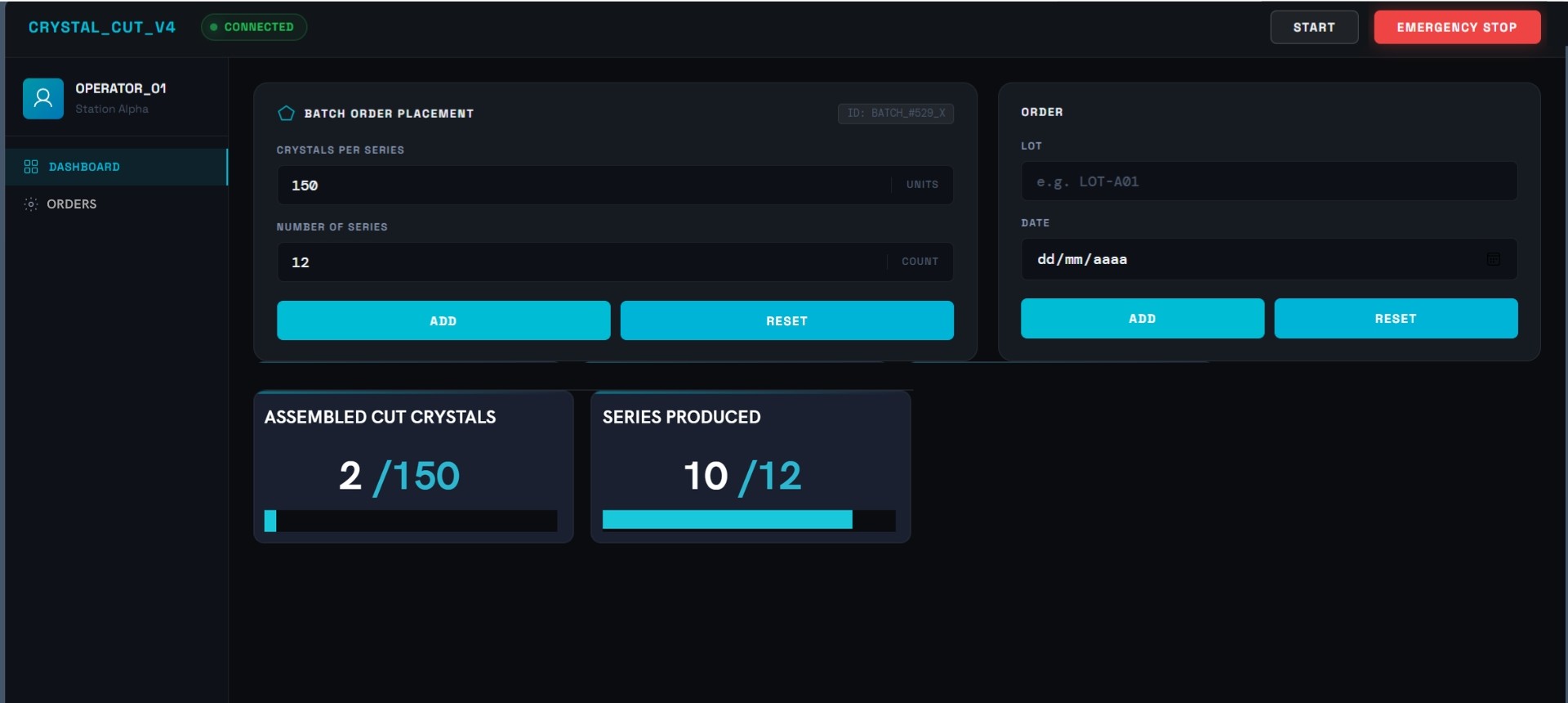
Dashboard, first section
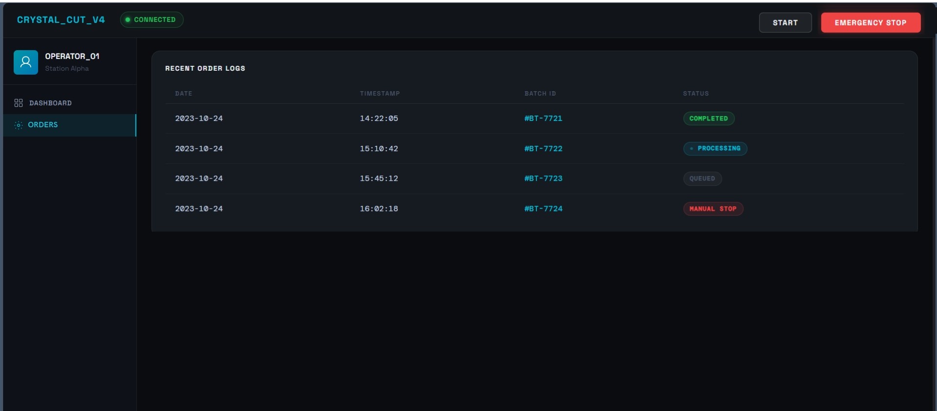
Orders
This view is essentially a historical log of all batches that have been run.
- Each row contains: date, time, lot, Batch ID, and a status badge.
- The possible statuses are: QUEUED (grey, just created), PROCESSING (blinking cyan, in progress), COMPLETED (green, finished successfully), and MANUAL STOP (red, manually stopped).
- The status of each row changes automatically based on messages arriving from the ESP32: when lote_completo arrives, the row changes to COMPLETED; when detenido arrives, it changes to MANUAL STOP.
- The Batch ID is incremental and persists between page reloads using localStorage.
Orders, second section
The interface was developed in Week 14. To see the full process of how it was made, refer to that week's documentation.
Try the Interface Live
You can open the dashboard directly in your browser and see exactly how it looks and behaves. The page automatically connects to the public HiveMQ MQTT broker as soon as it loads.
▶ View App⚠ Important: The dashboard only displays real-time data when a publisher is actively running and connected to the same MQTT broker. In my case, the publisher is the XIAO ESP32-S3 running my Arduino sketch (or alternatively, the professor's simulador.py script). If no publisher is running, the dashboard will still load and connect to the broker (the badge will turn green and show CONNECTED), but the metric cards will stay at zero because nothing is publishing sensor messages.
Code and Communication
Code
#include <AccelStepper.h> // Includes the AccelStepper library for non-blocking stepper motor control with acceleration ramps
#include <WiFi.h> // Includes the built-in WiFi driver for the Pico 2W
#include <PubSubClient.h> // Includes the MQTT client library used to publish/subscribe to the broker
#include <ArduinoJson.h> // Includes the JSON library used to build and parse MQTT payloads
// --- WiFi and MQTT ---
const char* WIFI_SSID = "Mihotspot"; // Stores the WiFi network name the board will connect to
const char* WIFI_PASSWORD = "12345678"; // Stores the WiFi password for that network
const char* MQTT_BROKER = "broker.hivemq.com"; // Stores the address of the public MQTT broker used as the message relay
const int MQTT_PORT = 1883; // Stores the standard TCP port used for MQTT (non-WebSocket)
const char* TOPIC_CONFIG = "ibero/arquitecturas/config"; // Topic the board subscribes to in order to receive batch configuration
const char* TOPIC_CONTROL = "ibero/arquitecturas/control"; // Topic the board subscribes to in order to receive INICIAR/DETENER commands
const char* TOPIC_SENSOR = "ibero/arquitecturas/sensor"; // Topic the board publishes to in order to report live progress
#define STEP_PIN 2 // Maps GPIO 2 to send step pulses to the DRV8825 driver
#define DIR_PIN 1 // Maps GPIO 1 to set the motor's rotation direction
#define ENABLE_PIN 0 // Maps GPIO 0 to enable/disable the DRV8825 driver (active-low)
#define Fisic_boton 3 // Maps GPIO 3 to read the physical push button
#define FULL_STEPS_PER_REV 200 // Defines the motor's native resolution: 200 full steps per revolution (1.8° per step)
#define MICROSTEP 1 // Defines the microstepping mode as 1 (full-step mode)
const long STEPS_RIGHT = (FULL_STEPS_PER_REV * MICROSTEP) / 4.30; // Calculates the number of steps for the rightward movement
const long STEPS_LEFT = (FULL_STEPS_PER_REV * MICROSTEP) / 5.30; // Calculates the number of steps for the leftward movement
const float MAX_SPEED = 1000.0; // Sets the maximum motor speed in steps per second
const float ACCEL = 2000.0; // Sets the motor's acceleration in steps per second squared
AccelStepper stepper(AccelStepper::DRIVER, STEP_PIN, DIR_PIN); // Creates the stepper motor object using the 2-wire driver interface
WiFiClient wifiClient; // Creates the underlying TCP client used for the MQTT connection
PubSubClient mqttClient(wifiClient); // Creates the MQTT client, built on top of the WiFi TCP client
// --- Motor state ---
bool running = false; // Tracks whether the motor sequence is currently active
int stage = 0; // Tracks which stage of the cycle is running (0 = right, 1 = left)
bool waiting = false; // Tracks whether the system is currently in the pause between movements
unsigned long waitStart = 0; // Stores the timestamp (millis) when the current pause started
// --- Batch counters ---
String lote = ""; // Stores the name of the current batch, received from the dashboard
int cristalesPorSerie = 0; // Stores how many crystals make up one series, received from the dashboard
int totalSeries = 0; // Stores the total number of series in the batch, received from the dashboard
int cristalActual = 0; // Counts how many crystals have been completed in the current series
int serieActual = 1; // Tracks which series number is currently in progress
bool configRecibida = false; // Flags whether a valid batch configuration has been received
// --- Physical button debounce ---
bool lastButtonState = LOW; // Stores the raw button reading from the previous loop pass
bool buttonState = LOW; // Stores the debounced (confirmed) button state
bool waitingForRelease = false; // Flags whether the system is waiting for the button to be physically released before accepting a new press
unsigned long lastDebounceTime = 0; // Stores the timestamp of the last detected change in button reading
const unsigned long DEBOUNCE_DELAY = 50; // Defines how many milliseconds to wait before trusting a button state change
// --- Non-blocking MQTT reconnection ---
unsigned long lastReconnectAttempt = 0; // Stores the timestamp of the last MQTT reconnection attempt
void enableDriver(bool enable) { // Defines a function to turn the stepper driver on or off
digitalWrite(ENABLE_PIN, enable ? LOW : HIGH); // Writes LOW to enable the driver (active-low) or HIGH to disable it
}
// --- Publish state to dashboard ---
void publicarEstado(const char* estado) { // Defines a function that publishes the current production state to the dashboard
StaticJsonDocument<256> doc; // Allocates a 256-byte JSON document on the stack
doc["estado"] = estado; // Adds the current state string (e.g. "ensamblando") to the JSON
doc["cristal_actual"] = cristalActual; // Adds the current crystal count to the JSON
doc["serie_actual"] = serieActual; // Adds the current series number to the JSON
doc["cristales_por_serie"] = cristalesPorSerie; // Adds the configured crystals-per-series value to the JSON
doc["total_series"] = totalSeries; // Adds the configured total series value to the JSON
doc["lote"] = lote; // Adds the batch/lot name to the JSON
char buffer[256]; // Declares a character buffer to hold the serialized JSON string
serializeJson(doc, buffer); // Converts the JSON document into a string and stores it in buffer
mqttClient.publish(TOPIC_SENSOR, buffer); // Publishes the JSON string to the sensor topic, sending it to the dashboard
Serial.print("[PUB] "); // Prints a label to the Serial Monitor for debugging
Serial.println(buffer); // Prints the published JSON content to the Serial Monitor
}
// --- Shared function: START ---
void iniciarSecuencia() { // Defines the function that starts the motor sequence
if (!running) { // Only starts if the sequence is not already running
running = true; // Marks the sequence as active
stage = 0; // Resets the cycle to stage 0 (right movement)
waiting = false; // Clears any pending wait state
stepper.moveTo(stepper.currentPosition() + STEPS_RIGHT); // Commands the motor to move STEPS_RIGHT steps from its current position
Serial.println("\n[INFO] Sequence STARTED."); // Logs that the sequence started
Serial.println("[MOTOR] Moving RIGHT..."); // Logs that the motor is moving right
}
}
// --- Shared function: STOP ---
void detenerSecuencia(bool esEmergencia) { // Defines the function that stops the motor sequence; takes a flag indicating if it's an emergency stop
if (running) { // Only stops if the sequence is currently running
running = false; // Marks the sequence as inactive
waiting = false; // Clears any pending wait state
stage = 0; // Resets the cycle stage back to 0
stepper.setCurrentPosition(stepper.currentPosition()); // Forces the library to treat the current position as the target, halting movement instantly
if (esEmergencia) { // If this stop was triggered remotely (emergency stop)
publicarEstado("detenido"); // Publishes a "detenido" status to notify the dashboard
Serial.println("\n[EMERGENCY STOP] Sequence stopped by emergency command."); // Logs the emergency stop event
} else { // If this stop was triggered by the physical button
Serial.println("\n[INFO] Sequence STOPPED safely."); // Logs a normal stop event
}
}
}
// --- MQTT Callback ---
void mqttCallback(char* topic, byte* payload, unsigned int length) { // Defines the function that runs automatically whenever a subscribed message arrives
StaticJsonDocument<256> doc; // Allocates a 256-byte JSON document to hold the parsed payload
DeserializationError err = deserializeJson(doc, payload, length); // Attempts to parse the incoming payload as JSON
if (err) return; // Exits the function early if the JSON could not be parsed
if (String(topic) == TOPIC_CONFIG) { // Checks if the message arrived on the config topic
lote = doc["lote"].as<String>(); // Extracts and stores the lot name from the JSON
cristalesPorSerie = doc["cristales_por_serie"]; // Extracts and stores the crystals-per-series value
totalSeries = doc["total_series"]; // Extracts and stores the total series value
cristalActual = 0; // Resets the crystal counter for the new batch
serieActual = 1; // Resets the series counter for the new batch
configRecibida = true; // Marks that a valid configuration has been received
Serial.println("[CONFIG] Batch configuration received."); // Logs that a configuration arrived
Serial.print(" Lot: "); Serial.println(lote); // Prints the received lot name
Serial.print(" Crystals/series: "); Serial.println(cristalesPorSerie); // Prints the received crystals-per-series value
Serial.print(" Total series: "); Serial.println(totalSeries); // Prints the received total series value
}
else if (String(topic) == TOPIC_CONTROL) { // Checks if the message arrived on the control topic
String comando = doc["comando"].as<String>(); // Extracts the command string from the JSON
if (comando == "INICIAR") { // Checks if the command is to start
if (configRecibida) { // If a configuration is already loaded
cristalActual = 0; // Resets the crystal counter before starting
serieActual = 1; // Resets the series counter before starting
}
iniciarSecuencia(); // Calls the function that starts the motor sequence
} else if (comando == "DETENER") { // Checks if the command is to stop
detenerSecuencia(true); // Calls the stop function, flagged as an emergency stop
waitingForRelease = false; // Clears the button release-wait flag, since this stop came from MQTT, not the button
lastButtonState = LOW; // Resets the last button reading
buttonState = LOW; // Resets the debounced button state
}
}
}
// --- WiFi ---
void connectWiFi() { // Defines the function that connects the board to WiFi
Serial.print("[WiFi] Connecting to "); // Prints a label before the network name
Serial.println(WIFI_SSID); // Prints the network name being connected to
WiFi.begin(WIFI_SSID, WIFI_PASSWORD); // Starts the WiFi connection attempt with the given credentials
int intentos = 0; // Declares a counter for connection attempts
while (WiFi.status() != WL_CONNECTED && intentos < 40) { // Loops until connected or 40 attempts (20 seconds) have passed
delay(500); // Waits half a second between checks
Serial.print("."); // Prints a dot to show progress
intentos++; // Increments the attempt counter
}
Serial.println(); // Prints a newline after the dots
if (WiFi.status() == WL_CONNECTED) { // Checks if the connection succeeded
Serial.print("[WiFi] Connected. IP: "); // Prints a success label
Serial.println(WiFi.localIP()); // Prints the IP address assigned to the board
} else { // If the connection failed
Serial.println("[WiFi] Connection failed. Check SSID/password."); // Prints a failure message
}
}
// --- Non-blocking MQTT reconnection ---
bool reconnectMQTT() { // Defines a function that attempts a single MQTT reconnection
String clientId = "pico2w_crystal_" + String(random(0xffff), HEX); // Builds a random unique client ID for this connection attempt
if (mqttClient.connect(clientId.c_str())) { // Tries to connect to the broker with that client ID
mqttClient.subscribe(TOPIC_CONFIG); // Subscribes to the config topic on success
mqttClient.subscribe(TOPIC_CONTROL); // Subscribes to the control topic on success
Serial.println("[MQTT] Connected and subscribed."); // Logs that the connection and subscriptions succeeded
return true; // Returns true to indicate success
}
return false; // Returns false if the connection attempt failed
}
void setup() { // Runs once when the board powers on
Serial.begin(115200); // Opens the Serial Monitor connection at 115200 baud
delay(1000); // Waits one second to let the Serial Monitor stabilize
pinMode(ENABLE_PIN, OUTPUT); // Configures the driver enable pin as an output
pinMode(Fisic_boton, INPUT); // Configures the button pin as an input (relies on external pull-down)
enableDriver(true); // Enables the stepper driver immediately
stepper.setMaxSpeed(MAX_SPEED); // Applies the maximum speed setting to the stepper object
stepper.setAcceleration(ACCEL); // Applies the acceleration setting to the stepper object
Serial.println("═══════════════════════════════════════"); // Prints a visual divider
Serial.println(" CRYSTAL_CUT_V4 - Raspberry Pi Pico 2W"); // Prints the project title
Serial.println("═══════════════════════════════════════"); // Prints another visual divider
connectWiFi(); // Calls the function to connect to WiFi
mqttClient.setServer(MQTT_BROKER, MQTT_PORT); // Configures the MQTT client with the broker address and port
mqttClient.setCallback(mqttCallback); // Registers mqttCallback as the function to run on incoming messages
reconnectMQTT(); // Performs the initial MQTT connection attempt
Serial.println("[INFO] System ready. Waiting for commands..."); // Logs that setup is complete
}
void loop() { // Runs continuously after setup()
// --- Maintain MQTT connection ---
if (!mqttClient.connected()) { // Checks if the MQTT connection has dropped
unsigned long now = millis(); // Reads the current timestamp
if (now - lastReconnectAttempt > 5000) { // Checks if at least 5 seconds have passed since the last attempt
lastReconnectAttempt = now; // Updates the timestamp of this attempt
if (reconnectMQTT()) lastReconnectAttempt = 0; // Attempts to reconnect; resets the timer if successful
}
} else { // If MQTT is connected
mqttClient.loop(); // Processes incoming MQTT messages and maintains the connection
}
// --- Physical button ---
bool reading = digitalRead(Fisic_boton); // Reads the current raw state of the physical button
if (waitingForRelease) { // Checks if the system is waiting for the button to be released
if (reading == LOW) { // If the button has been physically released
waitingForRelease = false; // Clears the release-wait flag
lastButtonState = LOW; // Resets the last button reading
buttonState = LOW; // Resets the debounced button state
lastDebounceTime = millis(); // Records the current time as the new debounce reference
}
stepper.run(); // Still runs the stepper engine even while waiting for release
return; // Exits the loop early, skipping the rest of the logic this pass
}
if (reading != lastButtonState) { // Checks if the raw reading changed since the last pass
lastDebounceTime = millis(); // Resets the debounce timer whenever the reading changes
}
if ((millis() - lastDebounceTime) > DEBOUNCE_DELAY) { // Checks if the reading has been stable longer than the debounce delay
if (reading != buttonState) { // Checks if this stable reading differs from the last confirmed state
buttonState = reading; // Updates the confirmed button state
if (buttonState == HIGH) { // Checks if the confirmed state is a press (HIGH)
if (!running) { // If the motor sequence is currently stopped
if (configRecibida) { // If a valid batch configuration exists
cristalActual = 0; // Resets the crystal counter before starting
serieActual = 1; // Resets the series counter before starting
}
iniciarSecuencia(); // Starts the motor sequence
} else { // If the motor sequence is currently running
detenerSecuencia(false); // Stops the sequence, flagged as a normal (non-emergency) stop
waitingForRelease = true; // Sets the flag so the next press requires a full release first
}
}
}
}
lastButtonState = reading; // Stores this pass's raw reading for comparison on the next pass
if (!running) { // If the motor sequence is not active
stepper.run(); // Still calls run() to let any pending deceleration finish
return; // Exits the loop early, skipping the state machine below
}
// --- State machine ---
if (waiting) { // Checks if the system is currently in the pause between movements
if (millis() - waitStart >= 15000) { // Checks if 15 seconds have elapsed since the pause started
waiting = false; // Ends the pause
stage++; // Advances to the next stage
if (stage > 1) stage = 0; // Wraps the stage back to 0 after stage 1
if (stage == 0) { // If the new stage is 0 (about to move right again)
cristalActual++; // Counts the just-completed cycle as one finished crystal
Serial.print("[CRYSTAL] "); // Prints a label
Serial.print(cristalActual); // Prints the updated crystal count
Serial.print("/"); // Prints a separator
Serial.print(cristalesPorSerie); // Prints the target crystals per series
Serial.print(" — Series: "); // Prints a label
Serial.print(serieActual); // Prints the current series number
Serial.print("/"); // Prints a separator
Serial.println(totalSeries); // Prints the total number of series
if (configRecibida && cristalActual >= cristalesPorSerie) { // Checks if the current series is now complete
publicarEstado("serie_completa"); // Publishes a "series complete" status to the dashboard
Serial.print("[SERIES] Series "); // Prints a label
Serial.print(serieActual); // Prints the completed series number
Serial.println(" completed."); // Prints the rest of the message
if (serieActual >= totalSeries) { // Checks if that was the last series in the batch
publicarEstado("lote_completo"); // Publishes a "batch complete" status to the dashboard
Serial.println("[BATCH] Batch completed. Motor stopping."); // Logs that the batch finished
running = false; // Stops the motor sequence
waiting = false; // Clears the wait state
stage = 0; // Resets the stage
configRecibida = false; // Clears the configuration, requiring a new one before the next batch
stepper.setCurrentPosition(stepper.currentPosition()); // Halts the motor instantly at its current position
return; // Exits the loop early since the batch is done
} else { // If more series remain
serieActual++; // Advances to the next series
cristalActual = 0; // Resets the crystal counter for the new series
publicarEstado("ensamblando"); // Publishes an "assembling" status to the dashboard
}
} else if (configRecibida) { // If the series is not yet complete but a config exists
publicarEstado("ensamblando"); // Publishes an "assembling" status to the dashboard
}
stepper.moveTo(stepper.currentPosition() + STEPS_RIGHT); // Commands the motor to move right again to start the next cycle
Serial.println("[MOTOR] Moving RIGHT..."); // Logs that the motor is moving right
} else if (stage == 1) { // If the new stage is 1 (move left)
stepper.moveTo(stepper.currentPosition() - STEPS_LEFT); // Commands the motor to move left
Serial.println("[MOTOR] Moving LEFT..."); // Logs that the motor is moving left
}
}
} else { // If the system is not currently in a pause
if (stepper.distanceToGo() == 0) { // Checks if the motor has finished its current movement
waiting = true; // Enters the pause state
waitStart = millis(); // Records the timestamp when the pause started
Serial.println("[MOTOR] Position reached. Waiting 15 seconds..."); // Logs that the motor reached its target and is pausing
}
}
stepper.run(); // Generates the actual step pulses needed to follow the motion profile, called every loop pass
}How the Loop and Its Cycles Work
The loop() function runs continuously and is organized into four cooperating blocks that all execute on every pass, without ever using delay() — this is what allows the motor, the button, and the MQTT connection to all be monitored at the same time.
On every loop pass, the code checks if the MQTT client is still connected. If it dropped, it attempts to reconnect every 5 seconds without freezing the rest of the program (no blocking while loop). If connected, mqttClient.loop() processes any incoming messages, which is what triggers mqttCallback().
The button state is read and debounced. A waitingForRelease flag prevents an immediate re-trigger after a stop. When a clean press is detected, the code toggles the motor: start it if it was stopped, or stop it if it was running.
This is the heart of the assembly motion, and it is a small state machine with two stages:
- Stage 0 (right): the motor moves STEPS_RIGHT steps clockwise.
- Stage 1 (left): the motor moves STEPS_LEFT steps counter-clockwise.
After the motor physically reaches its target (stepper.distanceToGo() == 0), the code does not immediately move to the next stage. Instead, it enters the waiting state and starts a 15-second timer (waitStart). Once 15 seconds have passed, the stage advances (stage++, wrapping back to 0 after 1), and the next movement is launched. This produces a continuous loop: right → wait 15s → left → wait 15s → right → ..., repeating indefinitely until the motor is stopped.
Each time the motor completes a full cycle (right + left, returning to stage 0), it counts as one finished crystal (cristalActual++). When the crystal count reaches cristalesPorSerie, the series is marked complete and published to the dashboard; if more series remain, the series counter advances and the crystal counter resets to zero. When the last series finishes, the whole batch is marked complete, the motor stops automatically, and the system waits for a new configuration.
Called on every single pass of loop(), regardless of what else happened. This is required by the AccelStepper library — it is the function that actually generates the step pulses needed to follow the acceleration ramp and reach the target position.
Communication: MQTT
Lines of Code Related to MQTT
#include <WiFi.h>
#include <PubSubClient.h>
#include <ArduinoJson.h>

const char* WIFI_SSID     = "Mihotspot";
const char* WIFI_PASSWORD = "12345678";
const char* MQTT_BROKER   = "broker.hivemq.com";
const int   MQTT_PORT     = 1883;
const char* TOPIC_CONFIG  = "ibero/arquitecturas/config";
const char* TOPIC_CONTROL = "ibero/arquitecturas/control";
const char* TOPIC_SENSOR  = "ibero/arquitecturas/sensor";

WiFiClient   wifiClient;
PubSubClient mqttClient(wifiClient);

void publicarEstado(const char* estado) { ... }
void mqttCallback(char* topic, byte* payload, unsigned int length) { ... }
void connectWiFi() { ... }
bool reconnectMQTT() { ... }

// Inside setup():
connectWiFi();
mqttClient.setServer(MQTT_BROKER, MQTT_PORT);
mqttClient.setCallback(mqttCallback);
reconnectMQTT();

// Inside loop():
if (!mqttClient.connected()) { ... reconnectMQTT(); ... }
else { mqttClient.loop(); }
This project uses three topics:
| Topic | Published by | Subscribed by | Purpose |
|---|---|---|---|
| ibero/arquitecturas/config | Dashboard | Pico 2W | Sends the batch configuration (lot name, crystals per series, total series) |
| ibero/arquitecturas/control | Dashboard | Pico 2W | Sends INICIAR / DETENER commands |
| ibero/arquitecturas/sensor | Pico 2W | Dashboard | Sends real-time progress (current crystal, current series, status) |
The Pico 2W subscribes to config and control, so any message published to those topics by the web dashboard triggers mqttCallback() automatically. The Pico 2W publishes to sensor every time something relevant happens (a crystal finishes, a series completes, the batch completes, or an emergency stop occurs), and the dashboard, which is subscribed to sensor, updates its counters and progress bars in real time as those messages arrive.
Results
Full Machine Assembly
Interfaces
-
Interface and MQTT connection
-
Dashboard and physical emergency stop
-
Orders tab
Machine Operation
Cycle operation
Full machine system operation
Files I used this week
files_fp.zip
Final Project Files
The following files are included in the package:
- 01_pieces/: SolidWorks part files (.SLDPRT) for all 19 machine pieces, including their exported STL files and a .3mf file for 3D printing (1st batch).
- 01_pieces/stl/: STL exports for all 19 pieces +
3D_prints_1st_part.3mfready for slicing. - 02_code/01_boton/02_boton.ino: Arduino sketch for the physical emergency stop button.
- 02_code/02_mqtt/03_mqtt.ino: Main Arduino sketch — stepper motor control with MQTT communication (Raspberry Pi Pico 2W).
- 03_3D_printers/3D_prints_1st_part.3mf: 3MF file for the first batch of 3D-printed parts.
- 03_3D_printers/3D_prints_2nd_part.3mf: 3MF file for the second batch of 3D-printed parts.
- 03_3D_printers/Gcode/: Pre-sliced G-code files for the Prusa MK4S (0.4 nozzle, 0.28 mm layer height, PLA) — 1h 37m and 3h 54m print times respectively.
- 04_board_kicad/: KiCad 9.0 project files for the 4-motor control board, including schematic and PCB layout designs.