Group assignment
Objective
-
Design a machine that includes mechanism + actuation + automation + application
-
Build the mechanical parts and operate it manually
-
Document the group project
Here I share the link to my group assignment.
Indivual assignment
- Document your individual contribution
This week’s challenge is to design and build a CNC machine. For me, this has been especially challenging because I am currently working remotely from Panama while taking the FabAcademy, which means I am physically separated from my team.
My main contribution focused on the programming aspect. To begin developing the motor control system, I relied on the electronics previously designed by Daniela Barranco, who created the schematic together with Joseph. Below is the schematic they provided.
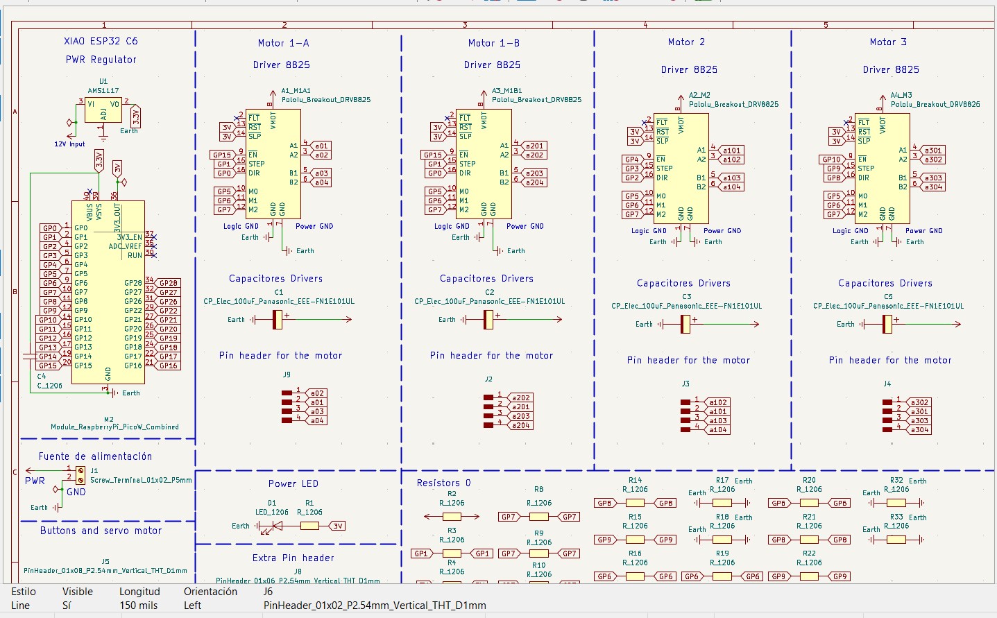
What interested me the most was understanding how the digital pins were connected to the motor drivers. In this case, the design uses DRV8825 drivers, which are commonly used to control stepper motors with precision.
To start programming, I first defined several parameters and global variables. The following section explains the structure and functionality of the code.
3-Axis CNC Control with Stepper Drivers (DRV8825)
This program controls a 3-axis CNC machine (X, Y, Z) using stepper motors and DRV8825 drivers.
Each axis has three main control pins: STEP, DIR, and EN, as well as an endstop switch used for homing.
The following section defines the pin configuration for each axis:
// X Axis
#define X_STEP 3
#define X_DIR  2
#define X_EN   4
#define X_ENDSTOP 13

// Y Axis
#define Y_STEP 1
#define Y_DIR  0
#define Y_EN   15
#define Y_ENDSTOP 14

// Z Axis
#define Z_STEP 9
#define Z_DIR  8
#define Z_EN   10
#define Z_ENDSTOP 16
Each STEP pin generates pulses to move the motor,
DIR controls the direction, and EN enables or disables the driver.
Motion Parameters
The variable PASOS_MM defines how many steps are required to move 1 mm.
In this case, 800 steps = 1 mm, meaning the system has high precision.
#define PASOS_MM 800.0
For example, if the motor performs 1600 steps, it will move 2 mm.
Soft Limits (Safety System)
Soft limits define the safe working area of the machine. These values prevent the tool from moving beyond physical boundaries.
#define X_MIN 0
#define X_MAX 200

#define Y_MIN 0
#define Y_MAX 150

#define Z_MIN 0
#define Z_MAX 50
If the system tries to move outside these limits, the motion will be stopped automatically.
It is important to highlight that these limits must be configured before uploading the program, as they do not represent the real physical limits of the machine. Instead, they are software-defined safety boundaries that must be adjusted according to the actual dimensions and travel range of the CNC system.
Global State Variables
The system uses global variables to track position and motion:
posX, posY, posZ: current position in stepsdx, dy, dz: movement distancestepsTotal: total steps of the movementrunning: indicates if the machine is movingsoftLimitHit: detects safety limit violations
Velocity is controlled using:
volatile int velMinUs = 2000;
volatile int velMaxUs = 400;
This defines acceleration and deceleration behavior.
Step Pulse Function
The function stepPulse() generates a pulse signal required to move a stepper motor one step.
inline void stepPulse(int pin) {
  digitalWrite(pin, HIGH);
  delayMicroseconds(2);
  digitalWrite(pin, LOW);
}
Limit Validation Function
The function dentroLimites() checks if a movement is within safe boundaries.
bool dentroLimites(float x, float y, float z) {

  if (x < X_MIN || x > X_MAX) return false;
  if (y < Y_MIN || y > Y_MAX) return false;
  if (z < Z_MIN || z > Z_MAX) return false;

  return true;
}
Stepper Control ISR (Core Logic)
The function stepperISR() is the core of the motion system.
It runs repeatedly using a timer and controls all three axes simultaneously.
It implements:
- Acceleration and deceleration using a smooth curve
- Multi-axis synchronized motion
- Real-time soft limit checking
Velocity is dynamically adjusted using this formula:
float factor = progress * progress * (3 - 2 * progress);
This creates a smooth start and stop (S-curve motion).
The system also uses error accumulation (errX, errY, errZ) to synchronize movement across axes,
similar to a Bresenham algorithm.
Movement Function (Steps)
The function moverXYZ() moves the motors based on step values.
void moverXYZ(long x, long y, long z) {

  dx = abs(x);
  dy = abs(y);
  dz = abs(z);

  digitalWrite(X_DIR, (x > 0));
  digitalWrite(Y_DIR, (y > 0));
  digitalWrite(Z_DIR, (z > 0));

  delayMicroseconds(200);

  stepsTotal = max(dx, max(dy, dz));

  errX = errY = errZ = 0;
  stepsDone = 0;

  running = true;

  add_repeating_timer_us(-velMinUs, stepperISR, NULL, &timer);
}
It performs:
- Direction setup
- Step calculation
- Timer activation
Movement Function (Millimeters)
The function moverXYZmm() converts millimeters into steps and verifies limits before moving.
void moverXYZmm(float x, float y, float z) {

  float actualX = posX / PASOS_MM;
  float actualY = posY / PASOS_MM;
  float actualZ = posZ / PASOS_MM;

  float newX = actualX + x;
  float newY = actualY + y;
  float newZ = actualZ + z;

  if (!dentroLimites(newX, newY, newZ)) {
    Serial.println("ERROR: Movimiento fuera de limites");
    return;
  }

  moverXYZ(x * PASOS_MM, y * PASOS_MM, z * PASOS_MM);
}
If the movement exceeds limits, it prints an error and cancels the motion.
Position Monitoring
The function imprimirPosicion() prints the current position in millimeters.
void imprimirPosicion() {
  Serial.print("X: ");
  Serial.print(posX / PASOS_MM);
  Serial.print("  Y: ");
  Serial.print(posY / PASOS_MM);
  Serial.print("  Z: ");
  Serial.println(posZ / PASOS_MM);
}
Homing System
The homing system moves each axis until it reaches its endstop switch, setting the origin position (0,0,0).
void homingEje() {

  Serial.println("Homing X...");
  homingEje(X_STEP, X_DIR, X_ENDSTOP, posX);

  Serial.println("Homing Y...");
  homingEje(Y_STEP, Y_DIR, Y_ENDSTOP, posY);

  Serial.println("Homing Z...");
  homingEje(Z_STEP, Z_DIR, Z_ENDSTOP, posZ);

  Serial.println("Homing completo");
}
Each axis is calibrated independently using homingEje().
Setup Function
In setup(), we configure all pins, enable the drivers, and initialize serial communication.
Finally, the system performs homing:
homingXYZ();
This ensures the machine starts from a known reference position.
Main Loop
Inside the loop(), the system:
- Checks for soft limit errors
- Executes a movement if the machine is idle
moverXYZmm(10, 5, 2);
This command moves the machine:
- 10 mm in X
- 5 mm in Y
- 2 mm in Z
After completing the motion, it prints the new position and waits 3 seconds before repeating.
Download File
CNC Desk Test
Step-by-step analysis
Movement performed by moverXYZmm(10, 5, 2);
📌 Case study
moverXYZ(8000, 4000, 1600)
- X = 8000 steps
- Y = 4000 steps
- Z = 1600 steps
Total steps: 8000
🔁 Step-by-step iterations
| Iteration | errX | errY | errZ | X | Y | Z |
|---|---|---|---|---|---|---|
| 1 | 8000 → 0 | 4000 | 1600 | ✔️ | ❌ | ❌ |
| 2 | 8000 → 0 | 8000 → 0 | 3200 | ✔️ | ✔️ | ❌ |
| 3 | 8000 → 0 | 4000 | 4800 | ✔️ | ❌ | ❌ |
| 4 | 8000 → 0 | 8000 → 0 | 6400 | ✔️ | ✔️ | ❌ |
| 5 | 8000 → 0 | 4000 | 8000 → 0 | ✔️ | ❌ | ✔️ |
🧠 Interpretation
The algorithm distributes steps proportionally across the axes.
- X moves in every iteration
- Y moves every 2 iterations
- Z moves every 5 iterations
Ratio: 1 : 0.5 : 0.2
🎯 Final result
- X = 10 mm
- Y = 5 mm
- Z = 2 mm
✔️ Perfect linear movement in 3D
📌 Case study (negative movement)
moverXYZmm(-20, -10, 2)
- X = -20 mm
- Y = -10 mm
- Z = 2 mm
🛑 Limit validation
Calculated values:
- newX = -20
- newY = -10
- newZ = 2
Result: The machine does not move.
⚙️ Behavior without limits (analysis)
If limits did not exist, the system would execute:
moverXYZ(-16000, -8000, 1600)
- dx = 16000
- dy = 8000
- dz = 1600
Directions:
- X → LOW (negative)
- Y → LOW (negative)
- Z → HIGH (positive)
🧠 Interpretation
- X moves 20 mm backward
- Y moves 10 mm backward
- Z moves up 2 mm
Conclusion: the algorithm supports negative movements, but they are limited by soft limits.
Once at this point, we must run the code on the machine to ensure it works correctly.
The next step would be to program the CNC control, but first I need to wait for my teammates to test it so I can continue developing.
Final Summary
This system is a complete CNC motion controller that:
- Controls 3 stepper motors simultaneously
- Uses acceleration and smooth motion profiles
- Implements safety limits (soft limits)
- Performs automatic homing
- Allows movement in millimeters
It is a solid base for building CNC machines, 3D printers, or robotic systems.
At this point, my teammates had already tested the CNC machine. Some changes were made, such as removing the endstops, which required adjustments in the programming. Additionally, I developed the CAM software that allows us to convert a DXF file into G-code format. Below is an image of the program interface. This software is responsible for communicating with the machine firmware, which executes the movements.
CAM SOFTWARE
Interface
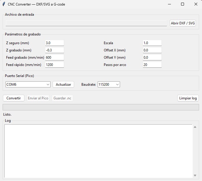
We can convert from DXF to G-code and from SVG to G-code. In addition, from this program we can send the generated G-code directly to the microcontroller, as well as save the G-code file. To run this program, we open it from the Windows CMD (terminal).
Download File
Next, I explain the code, which is written in Python.
To control the CNC workflow from design to execution, I developed a Python-based graphical interface. This application allows converting vector files (DXF/SVG) into G-code and sending them directly to the CNC machine.
CNC GUI — DXF/SVG to G-code Converter
This program provides a complete pipeline:
- Load a DXF or SVG file
- Convert geometry into G-code
- Preview parameters before machining
- Send commands directly to the CNC (Pico W)
Default Configuration Parameters
The system uses predefined parameters that control machining behavior:
DEFAULTS = {
    "z_seguro":     3.0,
    "z_grabado":   -0.3,
    "feed_rapido": 1200,
    "feed_grabado": 600,
    "escala":       1.0,
    "offset_x":     0.0,
    "offset_y":     0.0,
    "arco_pasos":    20,
    "baudrate":    115200,
}
These parameters define:
- z_seguro: safe height when the tool is not cutting
- z_grabado: cutting depth
- feed_rapido: travel speed without cutting
- feed_grabado: cutting speed
- escala: scaling factor of the design
- offset_x / offset_y: position adjustment
- arco_pasos: resolution of curves
- baudrate: serial communication speed
G-code Generation System
The class GcodeWriter is responsible for generating the G-code instructions from geometric data.
class GcodeWriter:
This class manages:
- Current tool position
- Tool state (cutting or not)
- Generated G-code lines
Initialization Commands
At the beginning of the program, the CNC is configured using standard G-code commands:
G28   ; go to home position
G21   ; set units to millimeters
The tool is then moved to a safe height:
G0 Z3
Linear Movement (G0 / G1)
Two types of movements are used:
- G0: rapid movement (no cutting)
- G1: controlled movement (cutting)
G0 X10 Y10
G1 X20 Y20 F600
Before cutting, the tool is lowered to the engraving depth.
Line Conversion
A simple line is converted into two steps:
- Move to starting point
- Execute cutting movement
def linea_xy(self, x1, y1, x2, y2):
This ensures efficient tool movement and avoids unnecessary cutting.
Polyline Conversion
Polylines are sequences of connected points.
def polilinea(self, puntos):
Each segment is converted into a continuous G1 movement.
Curve Approximation
Curves (circles, arcs, Bezier) are approximated using multiple small line segments.
def arco(self, cx, cy, radio, ang_ini, ang_fin):
This approach is used because the firmware does not support G2/G3 commands.
DXF Conversion
The function convertir_dxf() processes CAD files and supports:
- LINE
- POLYLINE
- CIRCLE
- ARC
- SPLINE
Each entity is converted into linear G-code instructions.
SVG Conversion
The function convertir_svg() reads vector graphics and converts them into CNC paths.
- Lines are directly converted
- Curves are approximated using multiple segments
Graphical User Interface
The interface is built using tkinter, which is included in Python.
Main interface features:
- File selection (DXF/SVG)
- Editable machining parameters
- Serial port selection
- Real-time log display
- Progress bar
Conversion Process
When the user clicks the "Convert" button, the system:
- Reads the selected file
- Generates G-code using GcodeWriter
- Displays conversion results
Serial Communication
The program sends G-code to the CNC using serial communication.
ser.write((linea + "\n").encode())
respuesta = ser.readline().decode().strip()
Each command is sent line by line, and the system waits for an ok response before continuing.
Error Handling
If an error is detected, the system automatically lifts the tool:
G0 Z5
This prevents damage to the material or machine.
Multithreading
The application uses threads to avoid freezing the interface during conversion or transmission.
threading.Thread(target=tarea)
This allows the user interface to remain responsive at all times.
Main Execution
The program starts by initializing the GUI:
root = tk.Tk()
app  = CNCApp(root)
root.mainloop()
para crear el software CAM he usado las siguientes bibliotecas
-
import ezdxf
from svgpathtools import svg2paths
from tkinter import ttk, filedialog, messagebox, scrolledtext
import threading
import os
import sys
import math
import time
This launches the application and waits for user interaction.
Once this has been explained, we now move on to the final code, which is responsible for executing the movements of the CNC machine. This code was developed using the Arduino IDE.
Dowload File
To start programming, I defined the hardware configuration and global variables needed to control the CNC system. This program combines real-time manual jog control with buffered G-code execution.
In this version, we implemented several changes compared to the first version of the code. The endstops were removed, and the machine origin is now set manually using buttons.
This system controls a CNC machine with three axes (X, Y, Z). The X axis uses two synchronized stepper motors.
At this stage, this is the final firmware that controls the CNC machine. It is programmed in Arduino IDE and runs on a Raspberry Pi Pico W 2, managing motors, buttons, G-code, and the tool servo.
General Architecture
This firmware integrates multiple systems working together:
- DRV8825 drivers (X dual motor, Y, Z)
- Direct Jog control using buttons
- Buffered G-code execution
- Smooth motion using acceleration (Smoothstep)
- Multi-axis synchronization (Bresenham algorithm)
- Servo control for tool orientation
- Soft limits for safety
Pin Configuration
Each axis uses STEP, DIR, and EN pins.
The X axis uses two motors working in parallel.
// X Axis (Dual Motor)
#define X1_STEP 16
#define X1_DIR  17
#define X1_EN   18

#define X2_STEP 7
#define X2_DIR  8
#define X2_EN   6

// Y Axis
#define Y_STEP  1
#define Y_DIR   2
#define Y_EN    0

// Z Axis
#define Z_STEP  4
#define Z_DIR   5
#define Z_EN    3
All drivers are enabled using EN = LOW.
Manual Control (Buttons)
Physical buttons are used for manual movement (Jog) and to define the machine origin.
#define PIN_ORIGEN_XY 19
#define PIN_ORIGEN_Z  13
#define PIN_X_PLUS    28
#define PIN_X_MINUS   27
#define PIN_Y_PLUS    26
#define PIN_Y_MINUS   22
#define PIN_Z_PLUS    21
#define PIN_Z_MINUS   20
- Jog: moves the axis while the button is pressed
- Origin: sets the current position to (0,0,0)
Motion Parameters
#define PASOS_MM      800.0
#define VEL_MIN_US    2000
#define VEL_MAX_US    400
#define JOG_DELAY_US  600
PASOS_MM: steps per millimeterVEL_MIN_US: initial speed (slow)VEL_MAX_US: maximum speedJOG_DELAY_US: manual movement speed
Soft Limits (Safety)
#define X_MIN   0.0
#define X_MAX   220.0
#define Y_MIN   0.0
#define Y_MAX   200.0
#define Z_MIN  -10.0
#define Z_MAX    5.0
These limits prevent the machine from moving outside its safe working area.
Buffer System (G-code)
The buffer stores movements before executing them, allowing smooth and continuous motion.
struct Movimiento {
  float x;
  float y;
  float z;
  float servoAng;
};
The buffer works as a circular queue using bufHead and bufTail.
Step Pulse Function
Each stepper motor moves one step when receiving a pulse.
inline void stepPulse(int pin) {
  digitalWrite(pin, HIGH);
  delayMicroseconds(2);
  digitalWrite(pin, LOW);
}
For the X axis, both motors move at the same time:
inline void stepPulseX() {
  digitalWrite(X1_STEP, HIGH);
  digitalWrite(X2_STEP, HIGH);
  delayMicroseconds(2);
  digitalWrite(X1_STEP, LOW);
  digitalWrite(X2_STEP, LOW);
}
Servo Control
The servo adjusts the tool orientation based on movement direction.
- Active only during
G1(cutting) - Inactive during
G0or Jog
float calcularAnguloServo(float dx_mm, float dy_mm)
The angle is calculated using atan2() and smoothed gradually.
Stepper ISR (Core System)
The function stepperISR() controls motion in real time using a timer.
- Smooth acceleration and deceleration
- Synchronized multi-axis movement
- Real-time limit checking
float factor = progress * progress * (3.0 - 2.0 * progress);
This creates smooth motion (ease-in / ease-out).
Launching a Movement
The function lanzarMovimiento() prepares and executes a movement:
- Calculates steps for each axis
- Sets direction
- Starts the timer (ISR)
- Updates servo target angle
Direct Jog Control
Jog mode moves the motors directly without using the buffer or ISR.
The motor moves continuously while the button is pressed.
void jogDirecto(...)
This provides immediate manual control of the machine.
G-code Interpreter
The firmware reads and executes G-code commands received via Serial.
G0→ fast movement (no cutting)G1→ cutting movement (activates servo)G21→ set units to millimetersG28→ reset position (home)G92→ define current positionM114→ report positionM280→ control servo manually
Each valid command responds with ok, allowing communication with the Python CAM software.
Main Loop
The loop() function continuously runs the system:
void loop() {
  leerBotones();
  leerGcodeSerial();
  ejecutarBuffer();
  actualizarServo();
}
- Reads buttons (manual control)
- Processes G-code from PC
- Executes buffered movements
- Updates servo smoothly
What I Learned – 3-Axis CNC Control System
During this project, I learned how to control a 3-axis CNC system using stepper motors and DRV8825 drivers. I understood how each axis (X, Y, Z) works independently but must be synchronized to achieve precise movement.
One of the most important concepts I learned is how stepper motors operate using three main signals:
STEP to move, DIR to define direction, and EN to enable the driver.
This helped me understand how motion is physically generated in CNC machines.
I also learned how to convert real-world units (millimeters) into motor steps using a conversion factor.
In my case, 800 steps = 1 mm, which allowed me to move the machine accurately.
Another key concept I learned was the implementation of soft limits. These limits define a safe working area and prevent the machine from moving beyond its physical boundaries, which is essential to avoid damage.
Additionally, I learned how to implement a homing system using endstops. This allows the machine to find its origin (0,0,0) and ensures that all movements are based on a known reference point.
I also understood how to synchronize multiple axes using a technique similar to the Bresenham algorithm, which ensures smooth and coordinated movement across X, Y, and Z.
One of the most advanced things I learned was how to implement acceleration and deceleration using a smooth curve (S-curve motion). This improves movement quality and reduces mechanical stress on the system.
Overall, this project helped me understand the fundamentals of CNC motion control, including precision movement, safety systems, and real-time motor control.
Mission accomplished! 😊