Project Development
18
Project Development
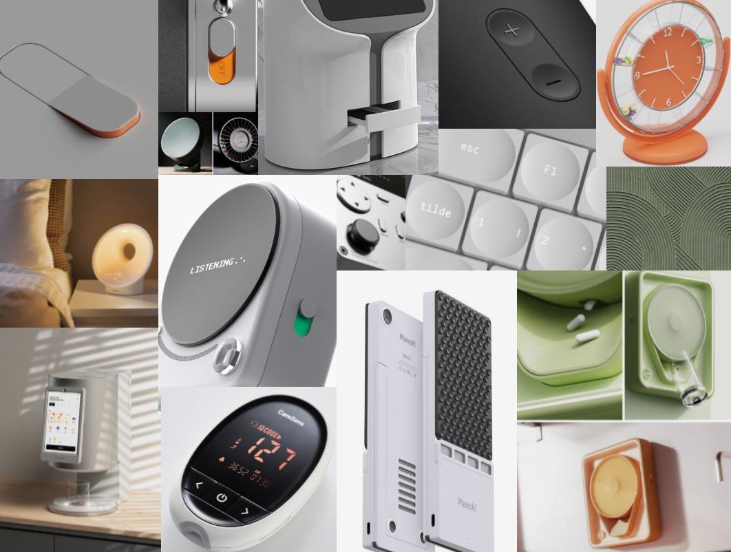
Full documentation of the MediBee pill dispenser
View Details
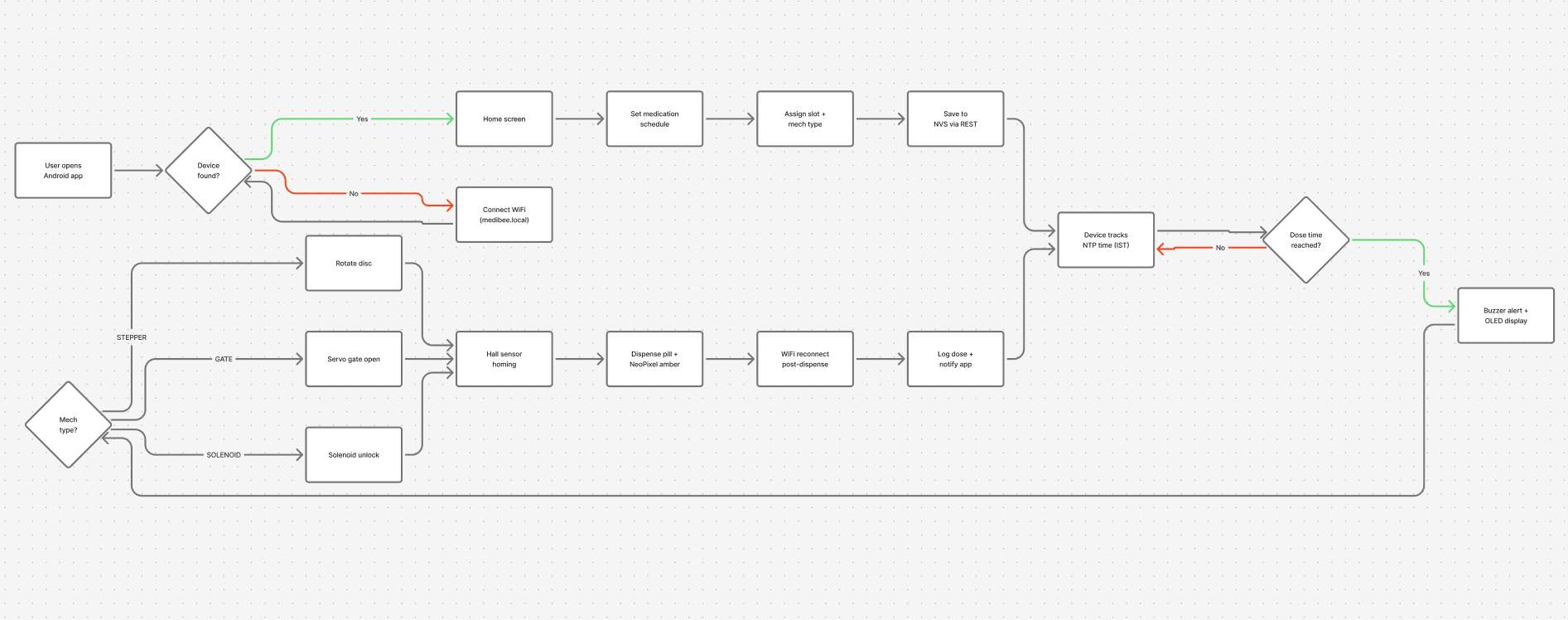
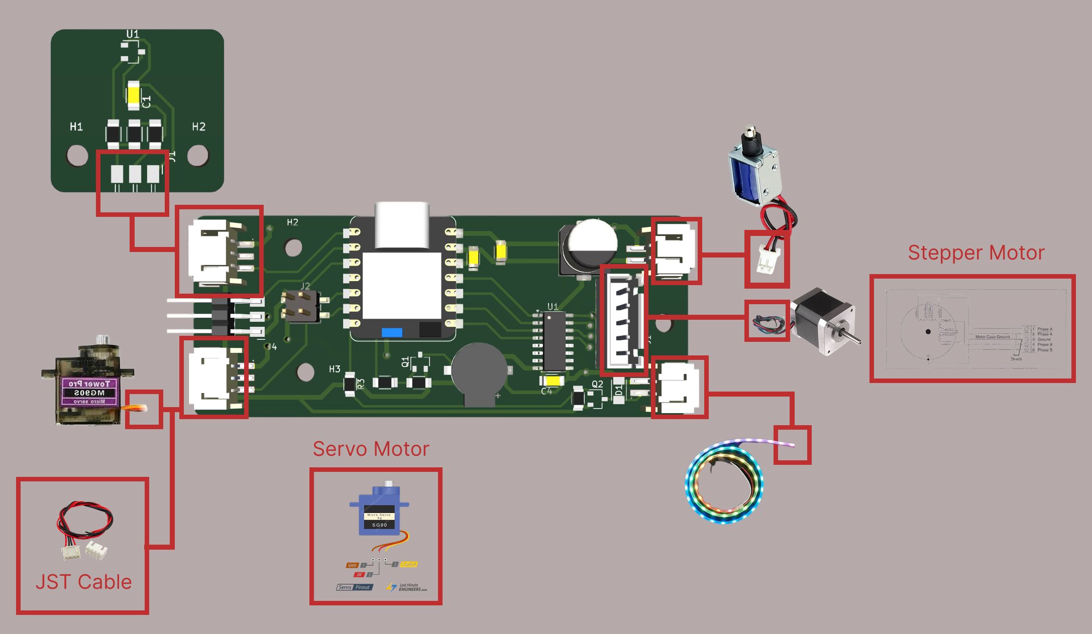
The hardware is a custom PCB built around a XIAO ESP32C6, driving a 28BYJ-48 stepper motor (rotating a medication disc), a servo (controlling the dispensing gate), a solenoid lock, a passive buzzer, and an SSD1306 OLED display.
On the software side, a React Native Android app communicates with the device over WiFi via a REST API hosted on the ESP32.
Each subsystem had been developed separately across previous weeks. System integration meant wiring them into a single enclosure, resolving hardware conflicts, and validating end-to-end behaviour from the phone app down to physical actuation.
The full system has four layers:
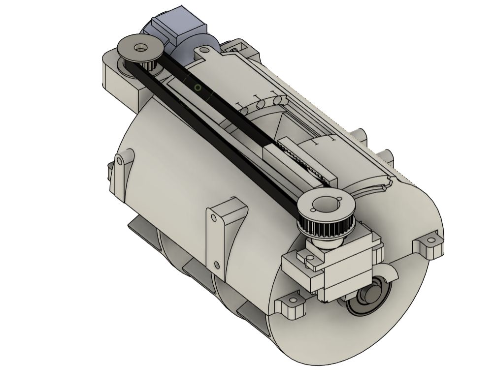
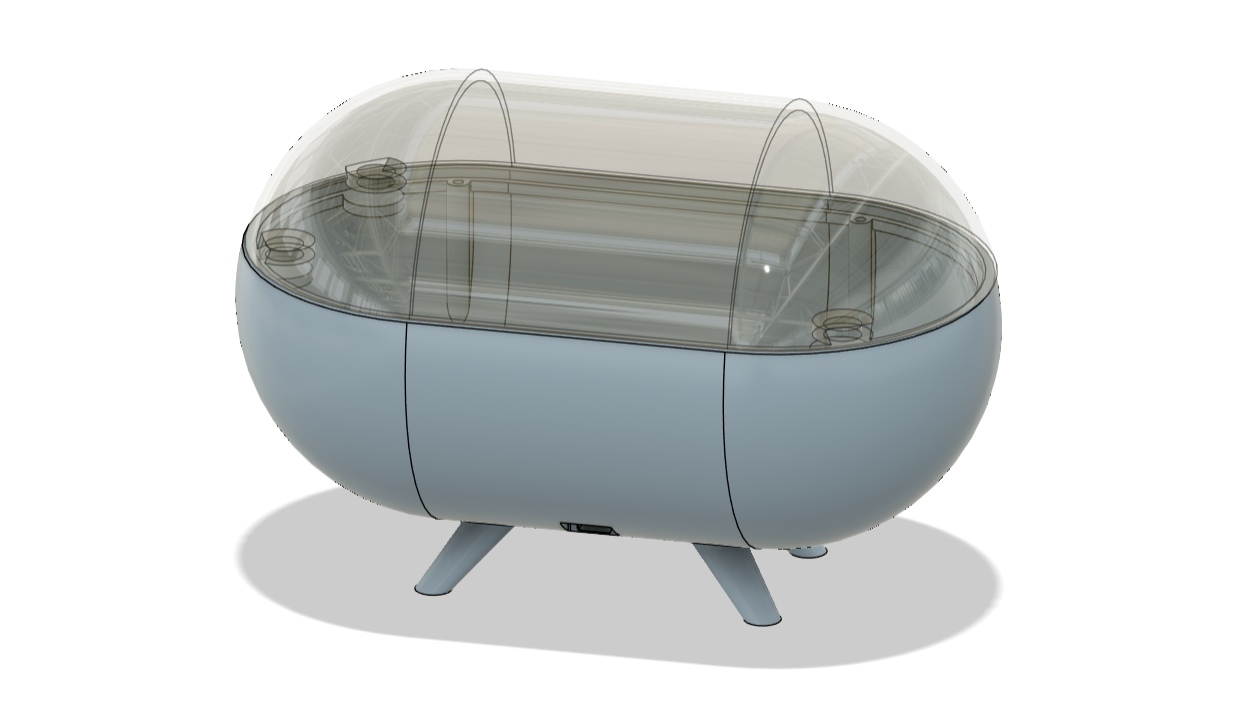
The enclosure was designed in Fusion 360 and printed in PLA..
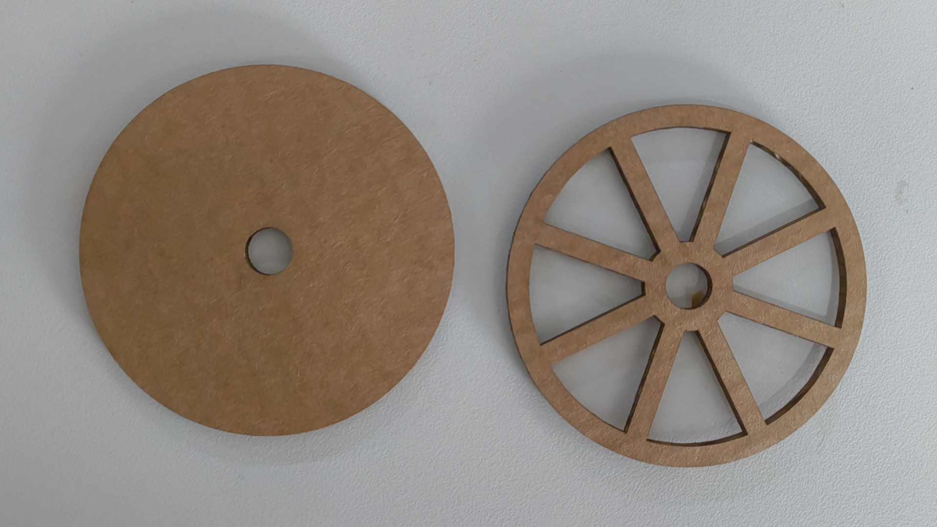
The medication disc was designed to rotate on a 8 mm steel rod. But there was a worry that it'll slip under the load. So I made a hole to put nails into the disc. So the disc is securely attached to the motor shaft. Under the same hole, I put another one to attch a magnet. This magnet is used for homing the disc.
The Stepper motor will rotate only once during the day. Preferable in the morning, right before the first dose.
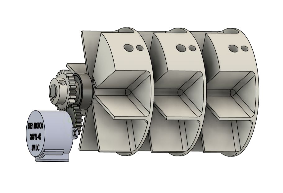
Then I made a mokeup in 3D printer.
This was the cardboard mokeup I made first. This made me decide that the diameter of the pill case was too large.
The servo controls the dispensing gate, a hinged flap that opens to drop a pill into the output chute.
With this mechanism, I can control which slot must dispense at one time. From the image, you can see that the compartment at the center is not covered. This dispenses the morning dose.
At noon, the servo rotated the door to the center, which opens the compartment at the side, and the noon dose dispenses.
The solenoid lock is mounted to the enclosure using two M2 screws through a printed bracket. Getting the angle right was important. If the solenoid was even slightly off, the plunger would catch on the latch instead of sliding through cleanly.
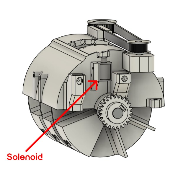
When the solenoid is activated, the plunger retracts and releases the door. The servo rotates the other door to the center. Then rotates back to the original position, which opens the compartment at the side, and the noon dose dispenses.
This is possible by attaching magnets to the side of the doors.
This was the hard part. The PCB, stepper motor, servo, solenoid, buzzer, OLED, and Hall sensors together produce about 30 cm of wiring inside the enclosure.
I added slots in the side of the lower half to mount the main PCB.
I imported the 3D design from Kicad and added it to the enclosure.
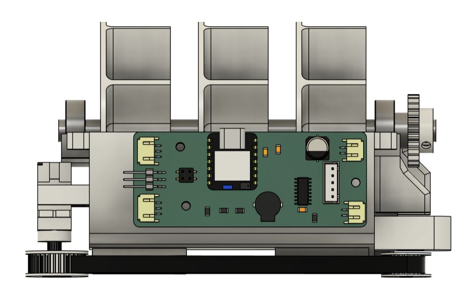
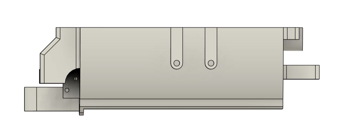
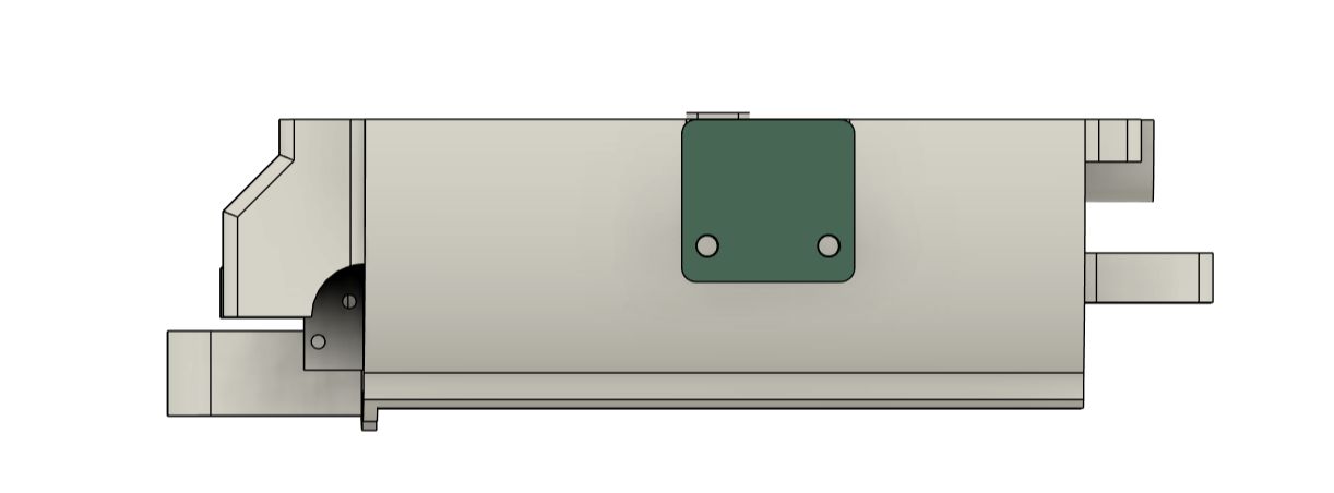
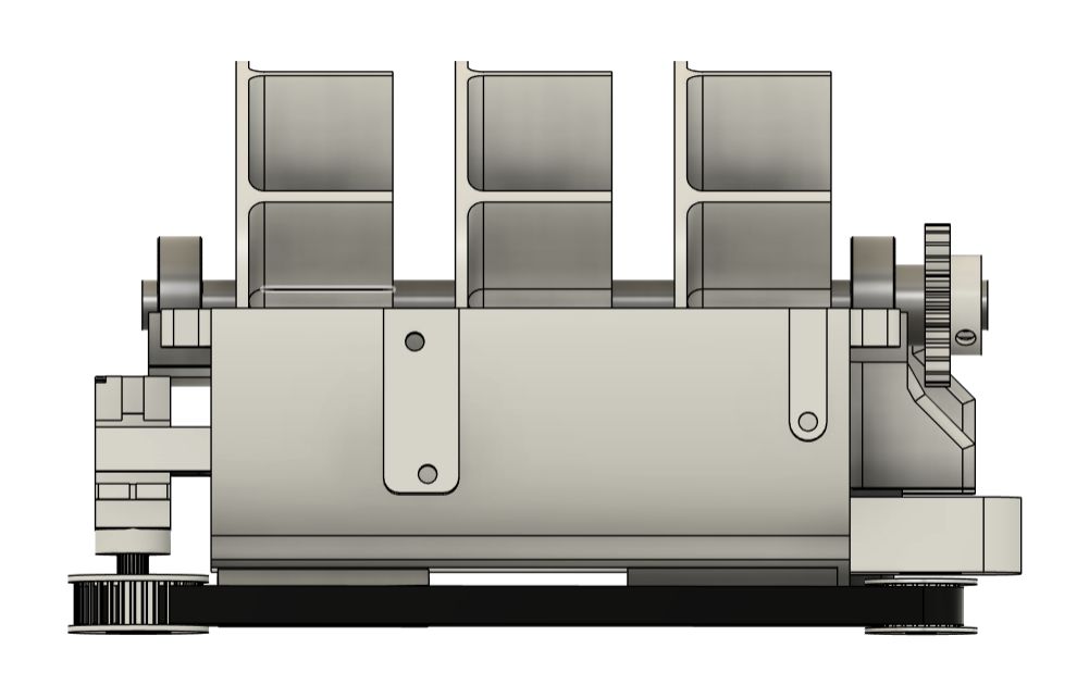
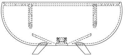
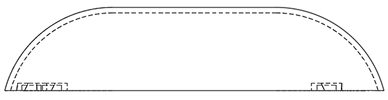
The enclosure is a two-part 3D-printed shell in PLA, split into an upper half housing the disc and gate mechanism, and a lower half housing the PCB, wiring, and solenoid. The two halves are held together with Magnets.
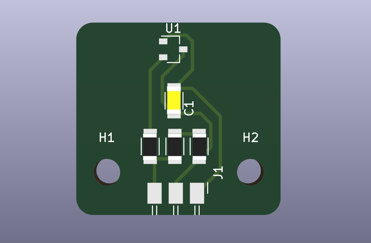
I designed the circuit boards in Kicad.
I needed two boards. One was the main board that connects to the Stepper and Servo motors, the solenoid and the buzzer. The second was the board for the Hall Effect sensors. This board will be placed close to the magnets in the enclosure.

| # | Category | Part | Qty | Unit Cost (INR) | Subtotal (INR) | Subtotal (USD) | Source | Link |
|---|---|---|---|---|---|---|---|---|
| 1 | MCU | XIAO ESP32-S3 module | 1 | 979 | 979 | $10.14 | Lab stock | Link |
| 2 | MCU | ATtiny 1624 | 1 | 139 | 139 | $1.44 | Lab stock | Link |
| 4 | Electronics | Schottky Diode | 1 | 13 | 13 | $0.13 | Lab stock | Link |
| 5 | Electronics | MP1584EN buck converter | 1 | 15 | 15 | $0.16 | Lab stock | Link |
| 6 | Electronics | SSD1306 OLED 0.96" 128x64 I2C | 1 | 169 | 169 | $1.75 | Lab stock | Link |
| 7 | Electronics | 12mm tactile push button | 1 | 3 | 3 | $0.03 | Lab stock | Link |
| 9 | Electronics | Active piezo buzzer 3.3–5V | 1 | 16 | 16 | $0.17 | Lab stock | Link |
| 10 | Electronics | Hall Effect Sensor | 1 | 39 | 39 | $0.40 | Lab stock | Link |
| 11 | Electronics | 28BYJ-48 stepper motor (5V) | 4 | 92 | 368 | $3.81 | Lab stock | Link |
| 12 | Electronics | ULN2003 driver board | 3 | 41 | 123 | $1.27 | Lab stock | Link |
| 14 | Electronics | Resistor 1k | 5 | .66 | .66 | $0.0068 | Lab stock | Link |
| 13 | Electronics | Resistor 10k | 2 | .66 | .66 | $0.0068 | Lab stock | Link |
| 16 | Electronics | Capacitor 100nF | 4 | 5 | 20 | $0.21 | Lab stock | Link |
| 17 | Electronics | Capacitor 10µF | 1 | 16 | 16 | $0.17 | Lab stock | Link |
| Total | ₹1,488 | $15.41 | ||||||
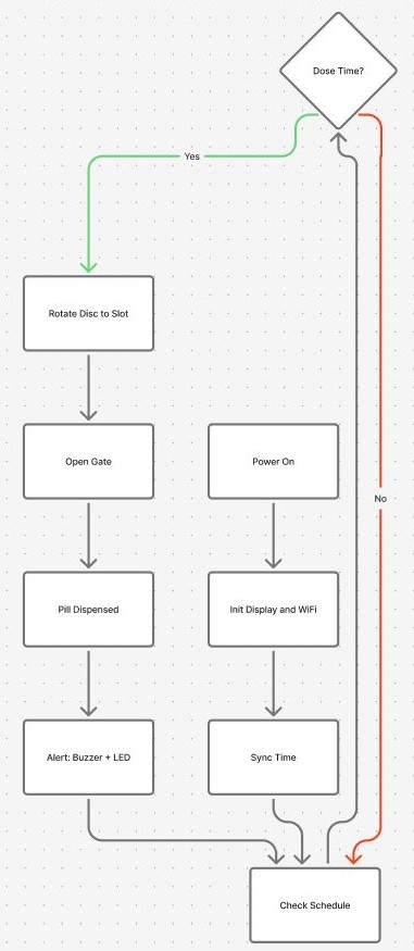
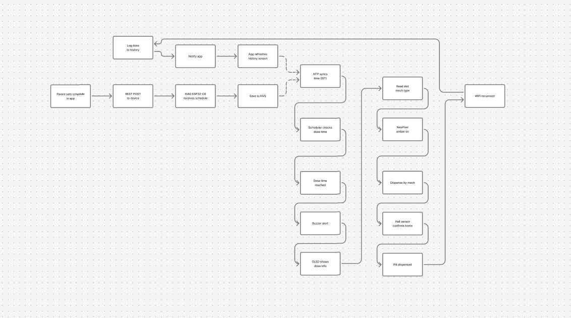
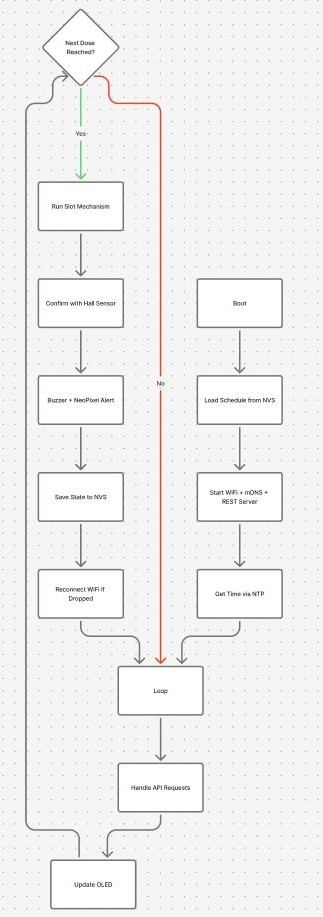
This is how the firmware behaves from power-on: it connects to WiFi and NTP once, then runs a loop that simultaneously serves the app's REST requests, keeps the OLED updated, and checks every ten seconds whether a dose is due.
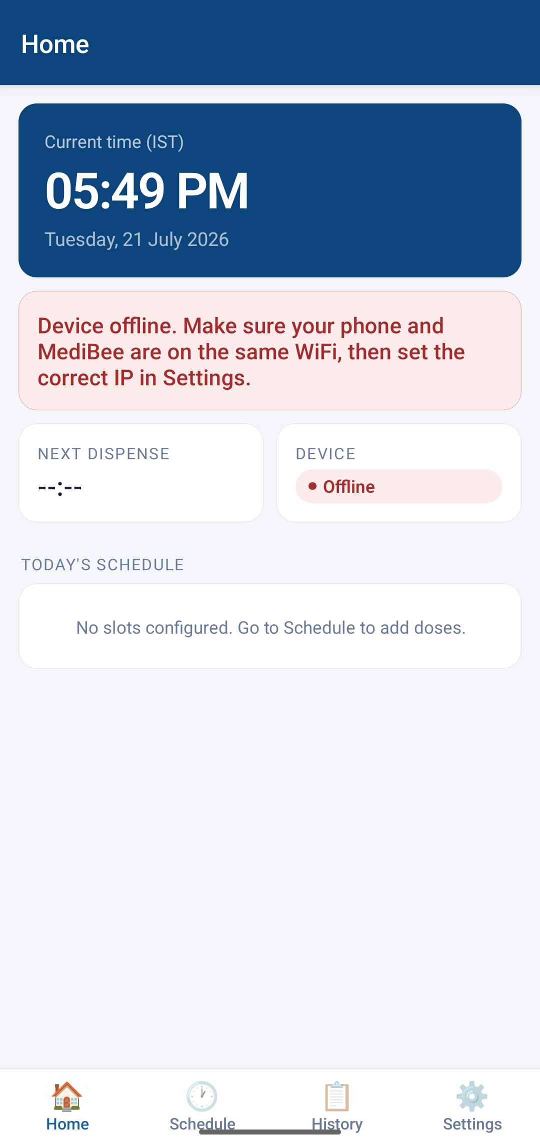
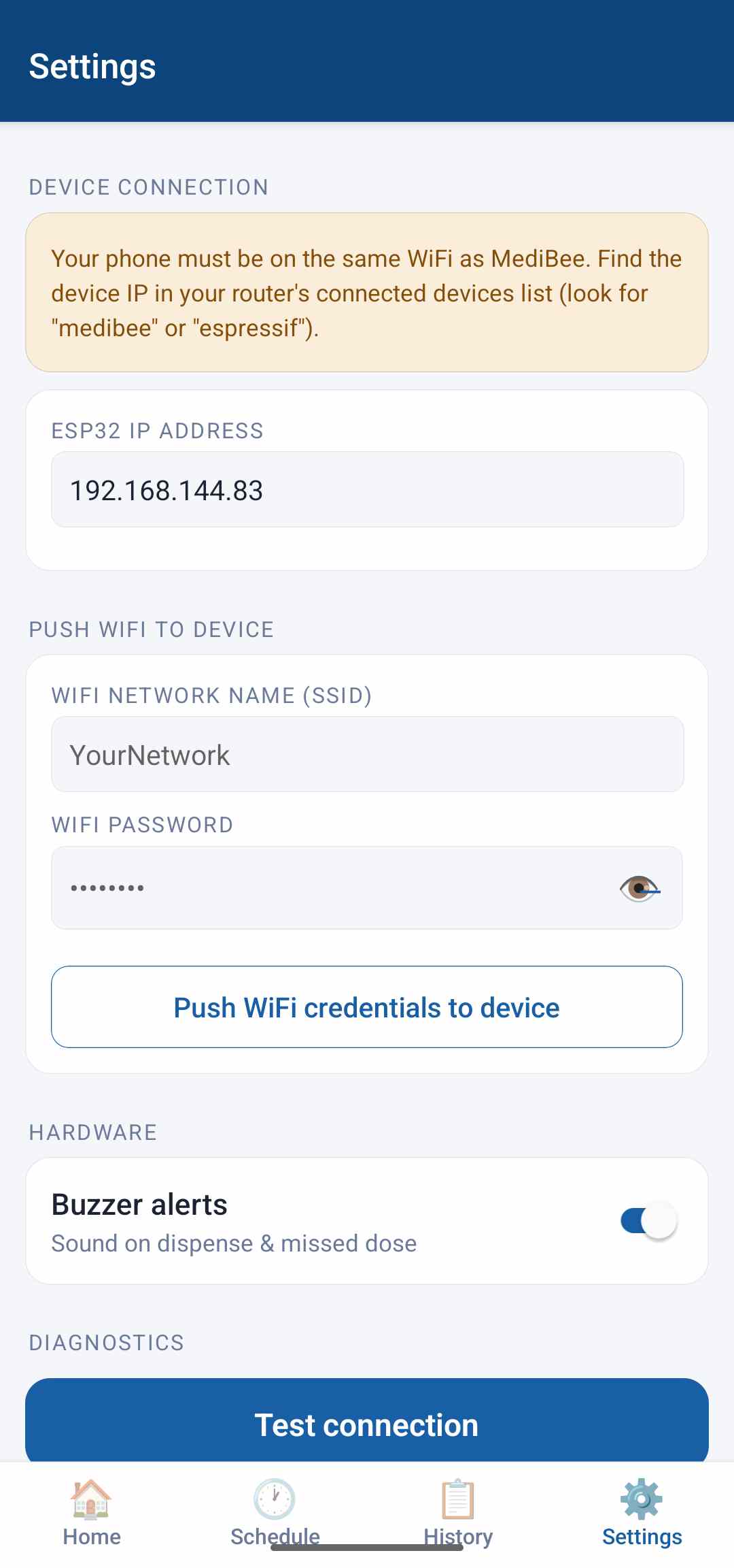
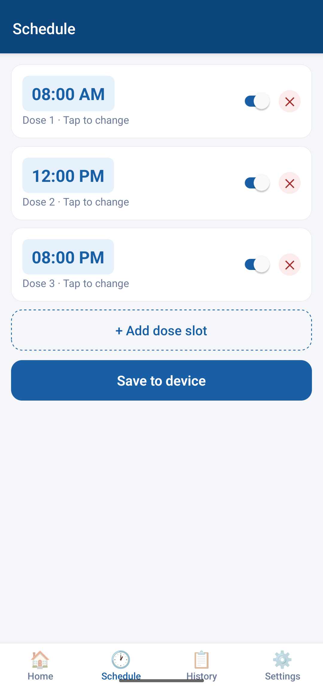
The companion app is a React Native app with four tabs — Home, Schedule, History, and Settings — that all talk to the ESP32 over the same REST API described above. It stores the device's IP address (and, optionally, WiFi credentials to push to the device) locally on the phone using AsyncStorage, so it reconnects automatically the next time the app opens.
The app polls /status every 15 seconds in the background to show an online/offline badge, independent of whichever tab is open.
Full documentation of the MediBee pill dispenser