COMPUTER-CONTROLLED MACHINING
Group Assignment
- Do your lab's safety training
- Test runout, alignment, fixturing, speeds, feeds, materials, and toolpaths for your machine
Individual Assignment
- Make (design + mill + assemble) something big (~meter-scale)
- Extra credit: Don't use fasteners or glue
- Extra credit: Include curved surfaces
- Extra credit: Use three-axis toolpaths
You can access the group assignment here.
Safety Training
Before using any of the machines this week, we went through the lab's safety training. The goal was to be aware of what can go wrong and how to prevent it, not just to follow rules but to actually understand the reasoning behind them.
Types of Hazards
CNC machining and other fabrication tools can cause several types of injuries if used carelessly:
- Splinters — wood fibres breaking off during cutting can embed in skin
- Cuts — from sharp edges on freshly cut material or from the cutting tool itself
- Burns — from friction heat on the material or tool, or from the spindle
- Impacts — from workpieces shifting, vibrating loose, or ejecting at speed
- Fires — fine sawdust accumulation near a hot spindle is a real fire risk
- Tool breaking — a snapped end mill or bit can become a fast-moving projectile
Personal Protective Equipment (PPE)
The correct PPE reduces the risk from all of the above:
- Glasses — safety glasses at all times around running machines; chips and dust travel fast
- Shoes — closed-toe shoes only; no sandals or bare feet on the shop floor
- Clothes — no loose clothing, no dangling sleeves or scarves near rotating parts
- Hair — tie back long hair before approaching any spinning machine
- Gloves — important nuance: gloves protect against splinters and sharp edges on cut material, but should never be worn near a rotating spindle or drill — a spinning bit can grab a glove and pull your hand in
Situational Awareness — Look, Listen, Smell
Machines communicate a lot of information through their senses. Training yourself to pay attention to them catches problems early:
- Look — watch the cut: is the bit deflecting? Is the workpiece moving? Is dust collecting near the spindle?
- Listen — a healthy cut sounds smooth and consistent. A screaming, rattling, or thudding sound means something is wrong — the feed rate is off, the bit is dull, or the workpiece is not held down properly
- Smell — burning wood or plastic means the tool is overheating. Stop the machine and find out why before continuing
Golden Rules
- Your hand is not a tool. Never use your fingers to push, hold, or guide material near a moving bit. Use push sticks, clamps, or proper work-holding
- Don't reach into a powered tool. If something needs adjusting — clearing a chip, repositioning the workpiece, checking a measurement — stop the machine first. A spindle spinning at 12,000 RPM doesn't slow down when you reach in
Emergency Procedures
- Emergency stop — know where the e-stop is before the machine starts, not after something goes wrong. On the ShopBot it is the large red button on the control box and there is also a spacebar shortcut in the software
- Assistance — never operate a CNC machine alone for the first time. Make sure someone else in the lab knows you are running a job so they can help if something goes wrong
Personal State
Don't use machines when you are tired, distracted, or rushing. Most accidents happen in the last ten minutes of a long session when attention drops. If you are not focused, the machine is the one in control.
Week Overview
This week focused on learning how computer-controlled machines can be used to fabricate objects from solid materials. The main objective was to understand the workflow of designing, preparing, and machining parts using digital fabrication tools.
For this week’s assignment, we were required to use a CNC milling machine to cut parts from a sheet of wood. Milling is a subtractive manufacturing process where a rotating cutting tool removes material from the workpiece to create the desired shape.
The assignment involved designing a structure that could be assembled without the use of screws or external fasteners. Instead, the parts needed to be connected using joints such as press-fit or interlocking joints. This required careful planning of the design, including measuring the material thickness and adjusting the slot sizes to ensure a tight fit.
Through this process, we learned how to prepare designs for CNC machining, generate toolpaths, and safely operate the milling machine to fabricate the final parts.
Machine Used
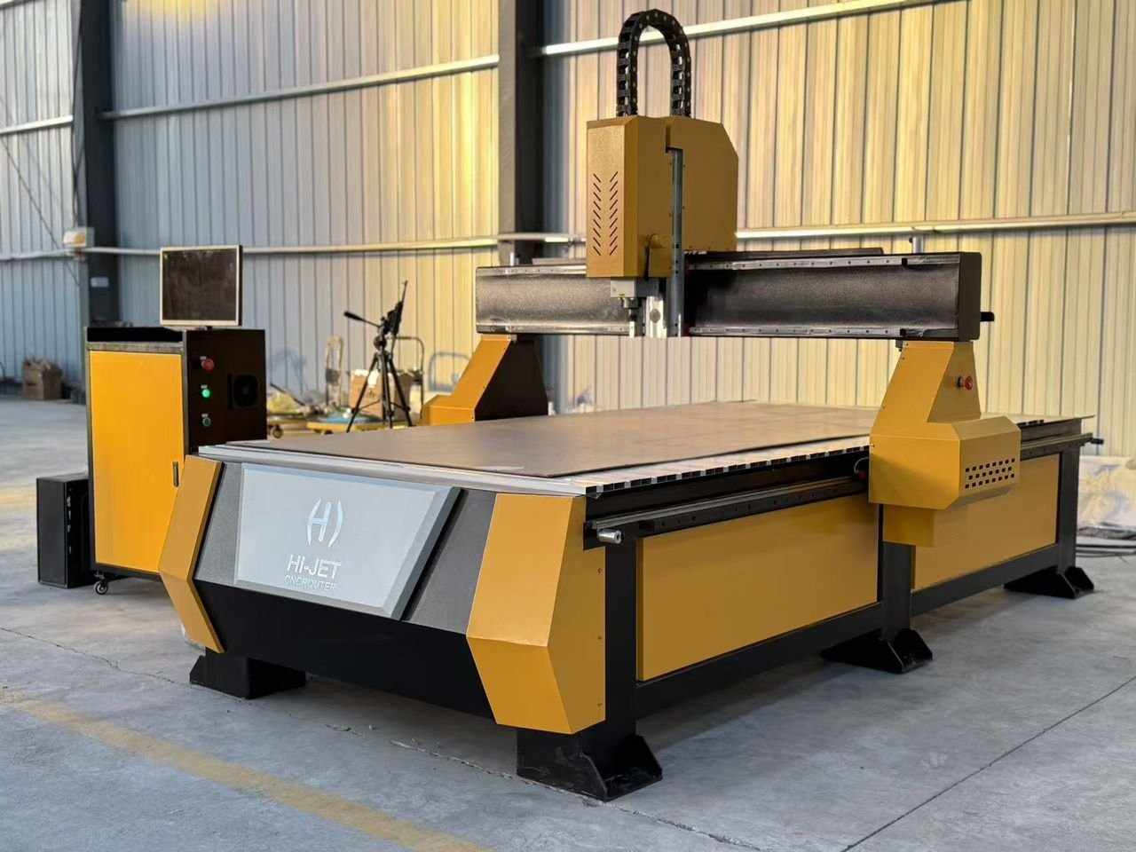
The machine we used for this assignment was the ShopBot PRSalpha 96 CNC Router.
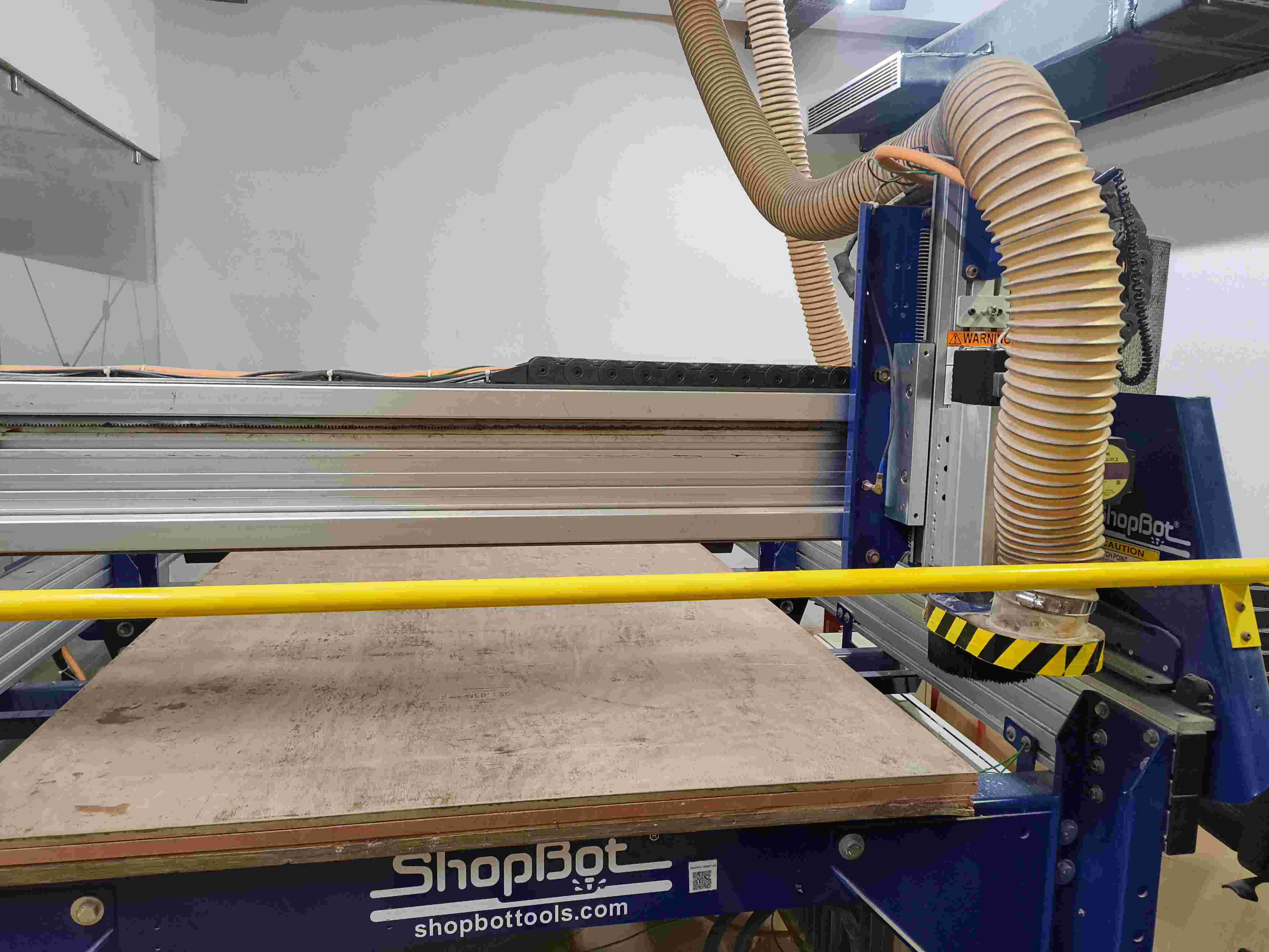
The ShopBot PRSalpha 96 is a large-format CNC router built for cutting sheet goods such as plywood, MDF, and solid wood. It can cut parts at the metre scale this week's assignment requires.
Key specs
- Cutting area — 96 × 48 inches (about 2440 × 1220 mm), matching a standard 4×8 ft sheet
- Axes — 3-axis (X, Y, Z)
- Drive system — rack-and-pinion on X and Y, lead screw on Z
- Spindle — variable speed router spindle, typically run at 12,000–18,000 RPM for wood
- Control software — ShopBot Control Software, accepting SBP toolpath files or standard G-code
Drills vs Mills
Drilling and milling are two common machining processes used to shape materials such as wood, metal, and plastic. Although both processes use rotating cutting tools, they are designed for different purposes and produce different results.
Drilling

Drilling is a machining process used to create round holes in a material. It uses a tool called a drill bit, which rotates and moves straight down into the material along its axis.
Key Characteristics
- The cutting motion occurs along the axis of the tool.
- Produces cylindrical holes.
- Commonly performed using a drill press or handheld drill.
- The cutting edges are mainly located at the tip of the drill bit.
Common Uses
- Creating holes for screws, bolts, or dowels.
- Preparing holes before threading.
- Making pilot holes in wood or metal.
Advantages
- Simple and fast process.
- Efficient for producing precise round holes.
- Requires relatively simple tools.
Limitations
- Can only produce round holes.
- Cannot create complex shapes or slots.
Milling
Milling is a machining process that removes material from a workpiece using a rotating cutting tool called a milling cutter or end mill. Unlike drilling, milling tools can move in multiple directions to create a variety of shapes and features.
Key Characteristics
- The cutting tool rotates while moving in multiple directions (X, Y, and Z axes).
- Can produce slots, pockets, contours, and flat surfaces.
- Commonly performed using milling machines or CNC machines.
- Cutting edges are located on the sides and sometimes the tip of the tool.
Common Uses
- Creating slots, grooves, and pockets.
- Shaping complex parts and contours.
- Producing flat surfaces and edges.
Advantages
- Capable of producing complex shapes.
- High precision, especially with CNC machines.
- Highly versatile machining process.
Limitations
- Requires more complex machines and setup.
- Generally slower and more expensive than simple drilling operations.
Key Differences
| Feature | Drilling | Milling |
|---|---|---|
| Purpose | Create round holes | Shape material and create complex features |
| Tool Used | Drill bit | End mill / milling cutter |
| Tool Movement | Mainly vertical (Z-axis) | Multiple directions (X, Y, Z) |
| Shapes Produced | Circular holes | Slots, pockets, contours, surfaces |
| Machine Type | Drill press, handheld drill | Milling machine, CNC router |
Lathe Machine
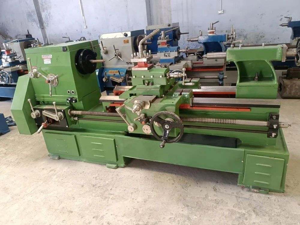
A lathe machine is a machining tool used to shape materials such as wood, metal, or plastic by rotating the workpiece against a cutting tool. Unlike milling, where the cutting tool rotates, in a lathe the workpiece rotates while the cutting tool remains relatively stationary and moves along the material to remove unwanted parts.
How a Lathe Works
In a lathe machine, the material is securely held in a rotating chuck attached to the spindle. As the workpiece spins, a cutting tool is slowly moved along its surface to remove material. This process allows the machine to create cylindrical shapes, threads, grooves, and smooth surfaces.
Main Parts of a Lathe
- Bed: The base of the lathe that supports all other components.
- Headstock: Contains the spindle and motor that rotate the workpiece.
- Chuck: A clamp-like device that holds the workpiece firmly.
- Tailstock: Supports the opposite end of the workpiece or holds drilling tools.
- Carriage: Moves the cutting tool along the length of the workpiece.
- Cutting Tool: The tool used to remove material from the rotating workpiece.
Common Lathe Operations
- Turning: Reducing the diameter of a workpiece to create cylindrical shapes.
- Facing: Creating a flat surface at the end of the workpiece.
- Drilling: Making holes along the center axis of the workpiece.
- Threading: Cutting screw threads on the surface of the material.
- Knurling: Creating textured patterns on the surface for grip.
- Grooving: Cutting narrow channels into the workpiece.
Types of Lathe Machines
- Wood Lathe: Used for shaping wooden objects such as bowls and table legs.
- Metal Lathe: Designed for precise machining of metal parts.
- CNC Lathe: Computer-controlled lathe used for automated and highly accurate machining.
Advantages
- Produces highly accurate cylindrical shapes.
- Can perform multiple operations on a single machine.
- Widely used in manufacturing and prototyping.
Limitations
- Mainly suitable for cylindrical or round parts.
- Complex shapes may require additional machines.
A key part of this week’s assignment was designing and fabricating a structure from wood using only joints, without the use of screws or external fasteners. This required careful consideration of material thickness, tolerances, and joint design to ensure that the parts fit together securely.
CNC Router
A CNC router (Computer Numerical Control router) is a computer-controlled cutting machine used to cut, carve, and shape materials such as wood, plastic, foam, and soft metals. It operates by following a set of digital instructions (G-code) to move a rotating cutting tool precisely across the material in multiple axes.
How a CNC Router Works
The CNC router moves its spindle (and attached cutting tool) along the X, Y, and Z axes based on coordinates generated from a CAD/CAM design. The material is held flat on a sacrificial bed using clamps, screws, or vacuum hold-down systems. The router's software translates the digital design into toolpaths, which define exactly how and where the tool moves to cut the material.
Main Parts of a CNC Router
- Frame/Bed: The structural base that supports the material and all moving parts.
- Spindle: The motor that rotates the cutting tool at high speed.
- Gantry: The bridge-like structure that moves along the X and Y axes over the bed.
- Z-axis: Controls the vertical movement of the spindle (depth of cut).
- Controller: The computer interface that sends movement commands to the machine.
- Collet: The clamp inside the spindle that holds the cutting bit securely.
Common Uses
- Cutting flat sheet materials (wood, plywood, MDF, acrylic).
- Engraving text and decorative patterns.
- Creating joinery and interlocking parts.
- 3D relief carving and sculpting.
- Producing signage, furniture parts, and prototypes.
Machine Used — ShopBot PRSalpha 96
The CNC router at FabLab Kochi is a ShopBot PRSalpha 96, a full-size gantry-style CNC router widely used in Fab Labs and professional woodworking shops worldwide. The "96" refers to the 96-inch (approximately 2440 mm) X-axis travel, allowing it to accommodate a full 4×8 ft (1220 × 2440 mm) sheet of plywood or MDF flat on the bed.
Key specifications of the ShopBot PRSalpha 96:
- Table size: 96 × 48 inches (2438 × 1219 mm) — fits a full 4×8 ft sheet
- Z-axis travel: approximately 6 inches (152 mm)
- Drive system: Alpha-series rack-and-pinion with servo motors for high speed and precision
- Spindle: variable-speed router spindle, typically run at 12,000–18,000 RPM for wood
- Control software: ShopBot 3 (SB3), communicates with the machine via USB
- File format: ShopBot Part Files (.sbp), generated by VCarve Pro using the ShopBot TC (MM) post-processor
- Positioning resolution: sub-millimetre, suitable for tight press-fit joinery
The PRSalpha series is designed for high-throughput sheet cutting. Its Alpha servo drives move significantly faster than stepper-motor alternatives, which reduces cutting time on large jobs. The machine uses a sacrificial spoilboard under the workpiece so the tool can cut completely through the material without damaging the steel bed.
Relationship Between a CNC Router and a Milling Machine
A CNC router and a CNC milling machine are closely related because both are computer-controlled machining tools that remove material using a rotating cutting tool. They operate using similar principles and are both examples of subtractive manufacturing.
Common Working Principle
Both machines work by following digital instructions generated from a CAD/CAM design. The cutting tool rotates at high speed while the machine moves along different axes to remove material and produce the desired shape.
- Both use rotating cutting tools.
- Both follow computer-generated toolpaths.
- Both operate on multiple axes (usually X, Y, and Z).
- Both remove material through milling operations.
Key Differences
Although they share the same basic concept, CNC routers and milling machines are designed for different types of materials and levels of precision.
| Feature | CNC Router | CNC Mill |
|---|---|---|
| Typical Materials | Wood, plastics, foam, soft metals | Metal, hard plastics, precision parts |
| Machine Structure | Lighter frame, larger work area | Heavier and more rigid frame |
| Cutting Speed | Higher speeds | Slower but more precise |
| Typical Use | Furniture parts, signs, panels | Mechanical parts and engineering components |
Summary
A CNC router can be considered a specialized type of milling machine designed mainly for softer materials like wood. Both machines use the same fundamental milling process, but they differ in strength, precision, and the materials they are designed to machine.
You can click here to learn more about the tools used a CNC Router.
Design Process: Doll House
For this week's individual assignment, I designed a parametric doll house in Fusion 360 intended to be cut from a sheet of plywood using the CNC router. The design uses press-fit interlocking joints, no screws or glue, so all tolerances had to be precisely calculated from the material thickness and measured kerf.
Step 1: Define Parameters
Before drawing anything, parametric variables were set up in Fusion 360 via Modify → Change Parameters. This ensures that any change to material thickness or joint tolerance automatically propagates through the entire design.
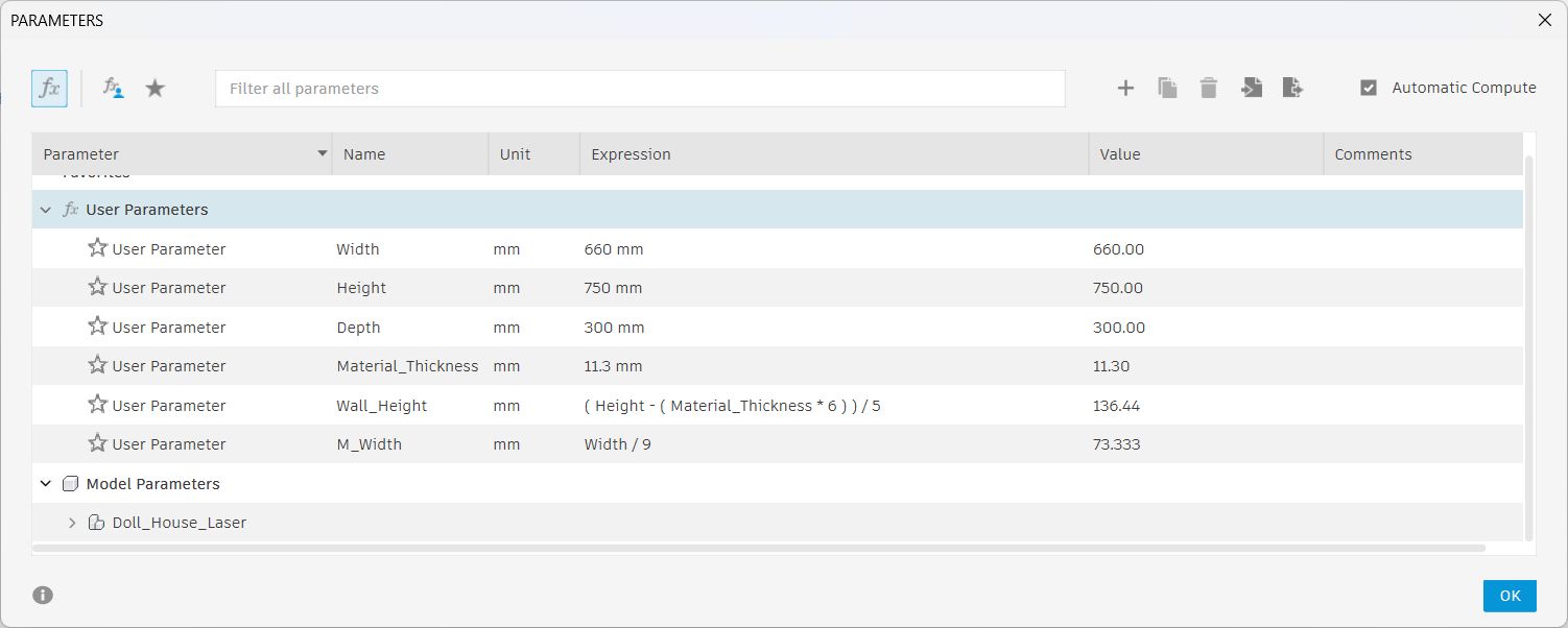
Parameter table showing material thickness, kerf, and slot width values.
Step 2: Create the Sketch
The doll house panels, front wall, back wall, side walls, floor, and roof, were sketched on a single plane.
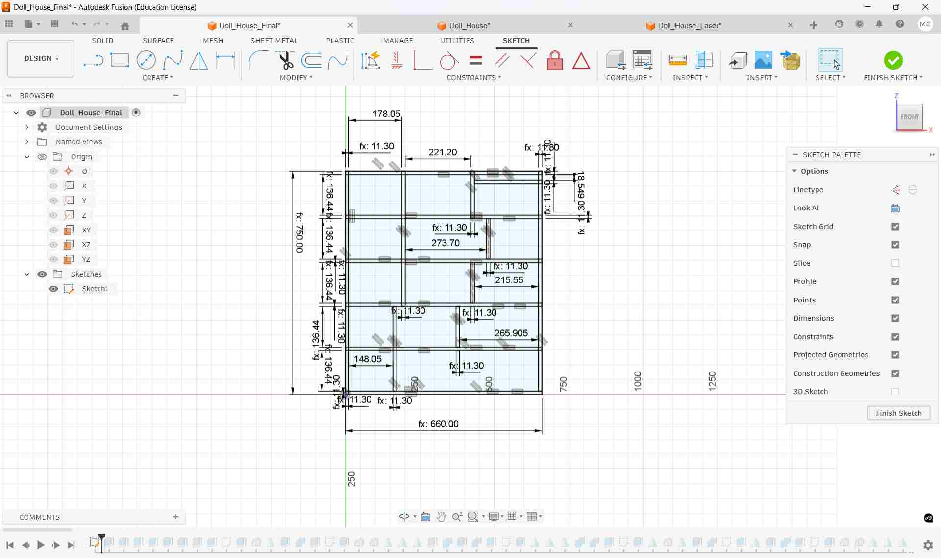
Parametric 2D sketch showing all doll house panels with joint notches.
Step 3: Extrude Panels to 3D
Each panel sketch profile was extruded to the material thickness using Create → Extrude. This converts the flat 2D shapes into solid 3D bodies, allowing the assembly to be visualised and verified before cutting.
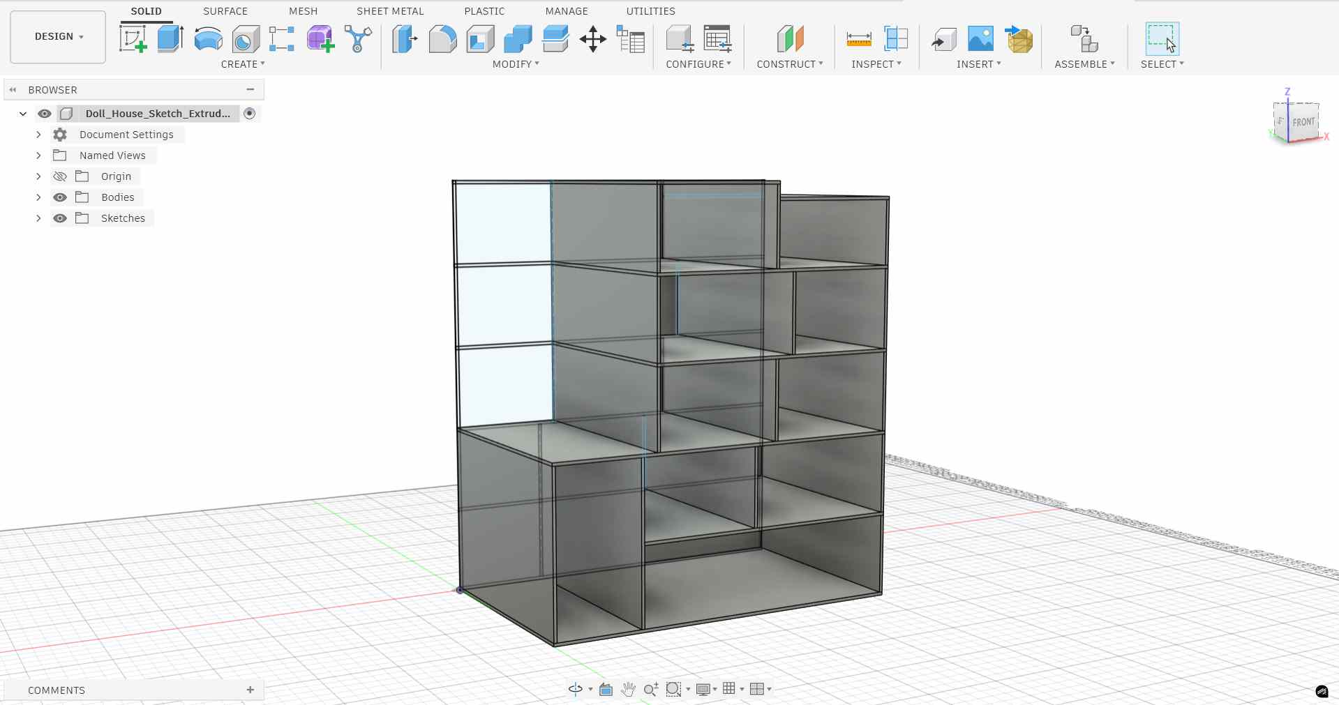
Initial panels extruded to material thickness.
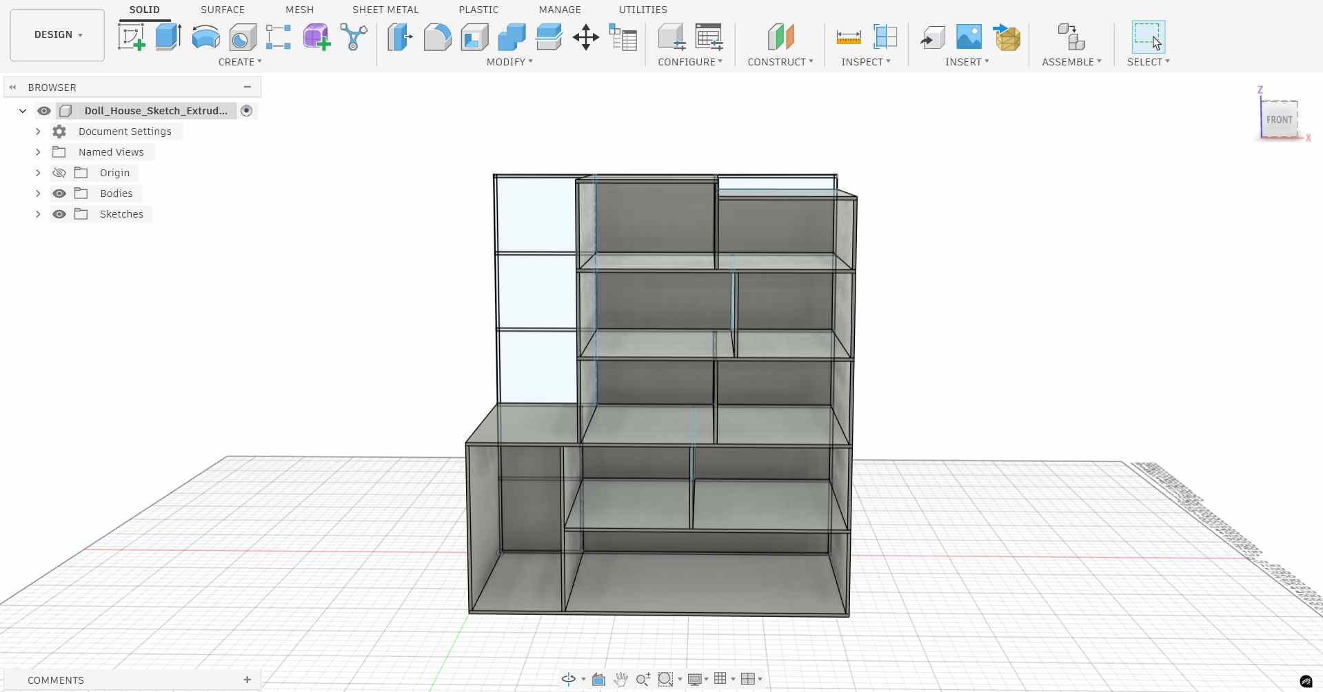
All panels extruded, full doll house structure visible.
Step 4: Add Joints
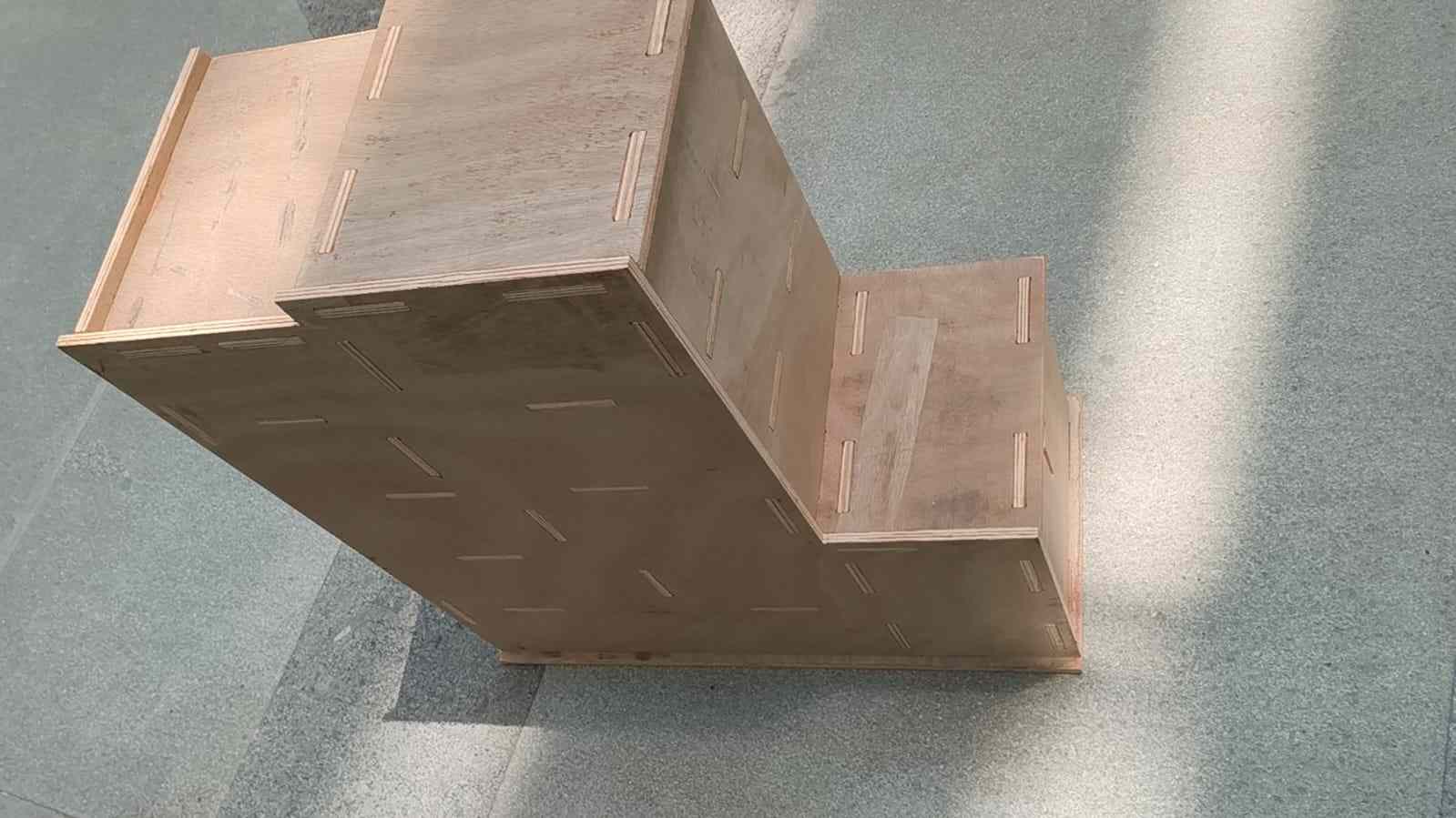
Press-fit T-slot joints were added to each panel edge where two panels intersect. Each slot has two key dimensions: the slot height equals the material thickness (so the mating panel slides in flush), and the slot width equals the full panel width divided by 9, giving the joint proportional sizing relative to the panel.
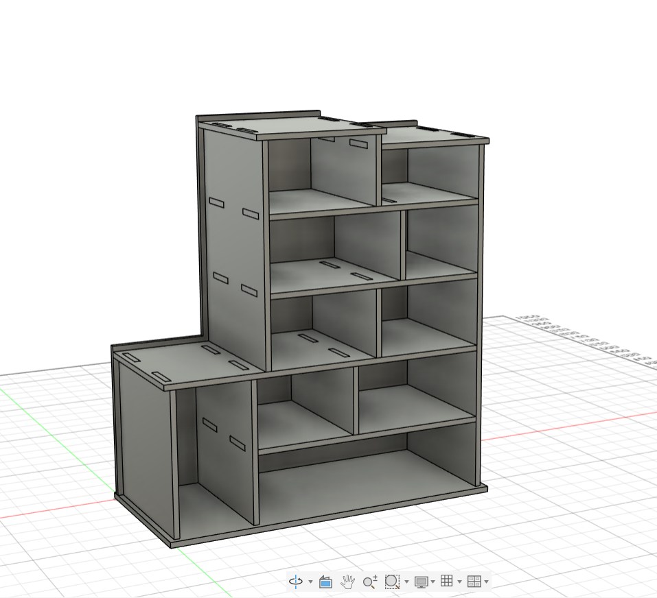
Completed model with press-fit joint notches cut into every connecting edge.
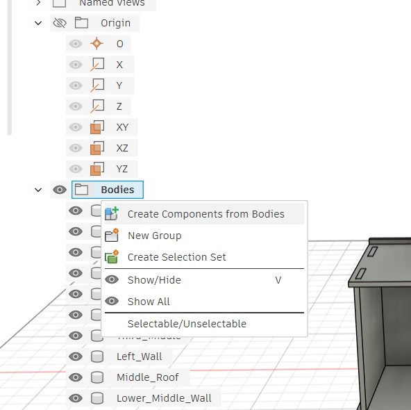
Step 5: Convert Bodies to Components
All the solid bodies were converted into individual Components using Right-click → Create Components from Bodies. This is required before using the Arrange function to lay all panels flat for the cutting layout.
Converting solid bodies to components in the Fusion 360 browser.
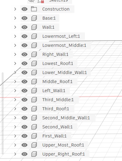
All doll house panels listed as individual components.
Step 6: Scale & Prepare for Sheet Layout
Before the final CNC cut, the design was scaled down to fit a smaller sheet for a test cut on the laser cutter. This allows the joint fit and overall proportions to be verified cheaply before committing to the full-size CNC run.
To find the correct scale factor, an online scale calculator was used. By entering a known dimension from the model and the target dimension for the laser test sheet, the tool computed the exact ratio to apply in Fusion 360.
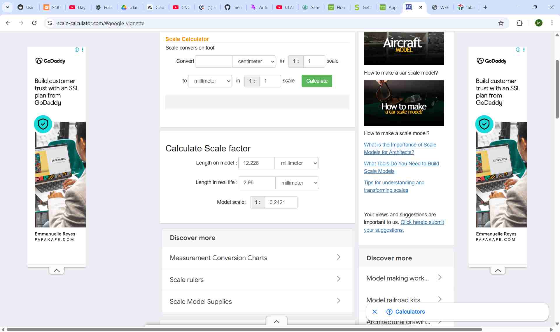
Scale calculator used to determine the exact ratio for scaling down to the laser cutter sheet size.
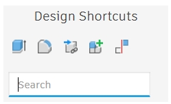
With the scale ratio known, the Scale command was applied in Fusion 360 using the Design Shortcuts panel, a quick-access command bar that allows any Fusion command to be run by typing its name. I pressed 's' to open the Design Shortcuts panel, then typed 's' to find and run the Scale command.
Design Shortcuts panel opened in Fusion 360.
Typing "S" surfaces the Scale command at the top of the list.

Before scaling, panels at full CNC size.

After scaling, panels reduced to fit the laser cutter sheet for test cutting.
Step 7: Arrange Panels Flat Using the Arrange Function
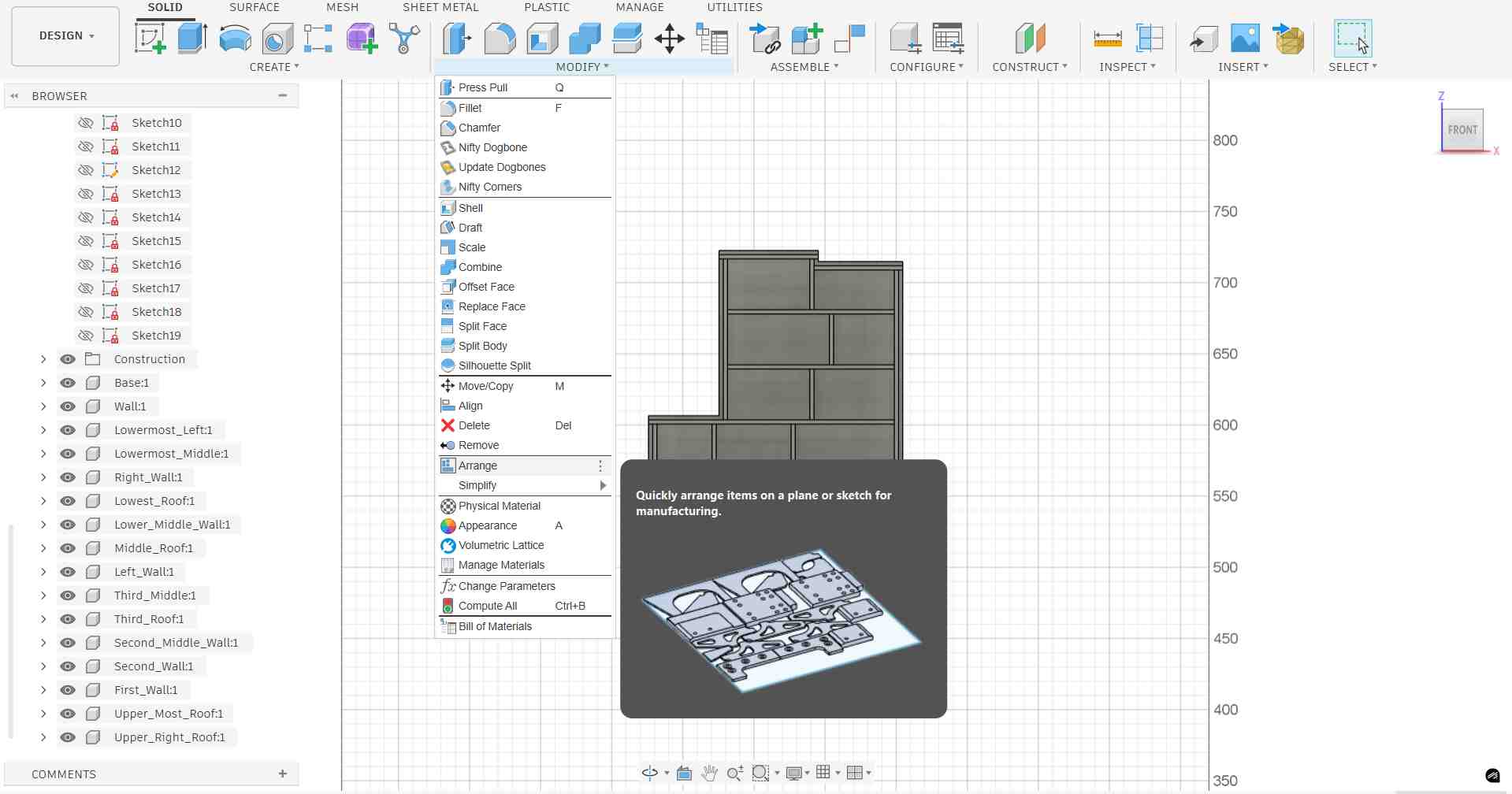
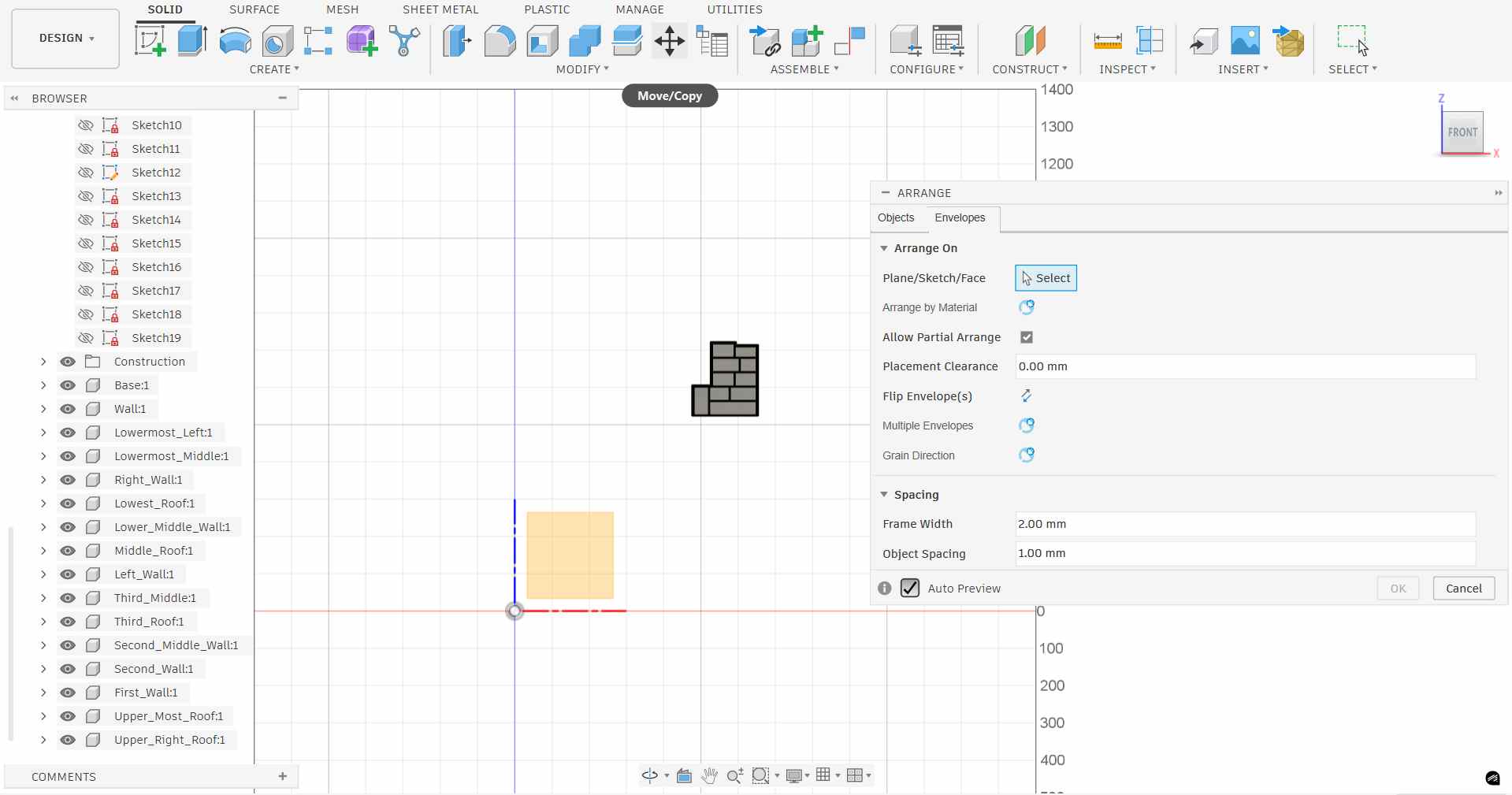
With all panels as components, the Arrange function (Modify → Arrange) was used to automatically lay all 3D components flat onto a single plane, simulating the flat sheet of plywood. This is an essential step before exporting for CNC cutting, as it places all parts in their correct orientation for a 2D cut file.
Arrange function dialog, select components, set spacing, and choose the target plane.
The Arrange function progressively lays out each component flat, nesting them efficiently within the sheet boundary:
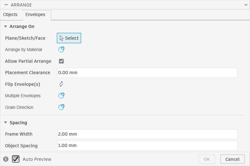
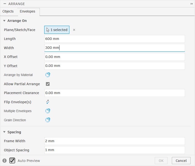
Go to the envelopes tab
Choose the plane you want to arrange the components on
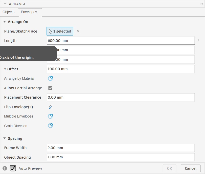
Give the length, width, frame width and object spacing
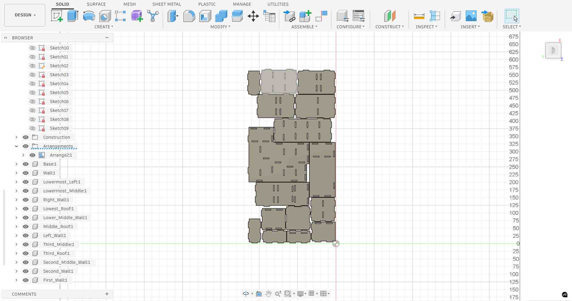
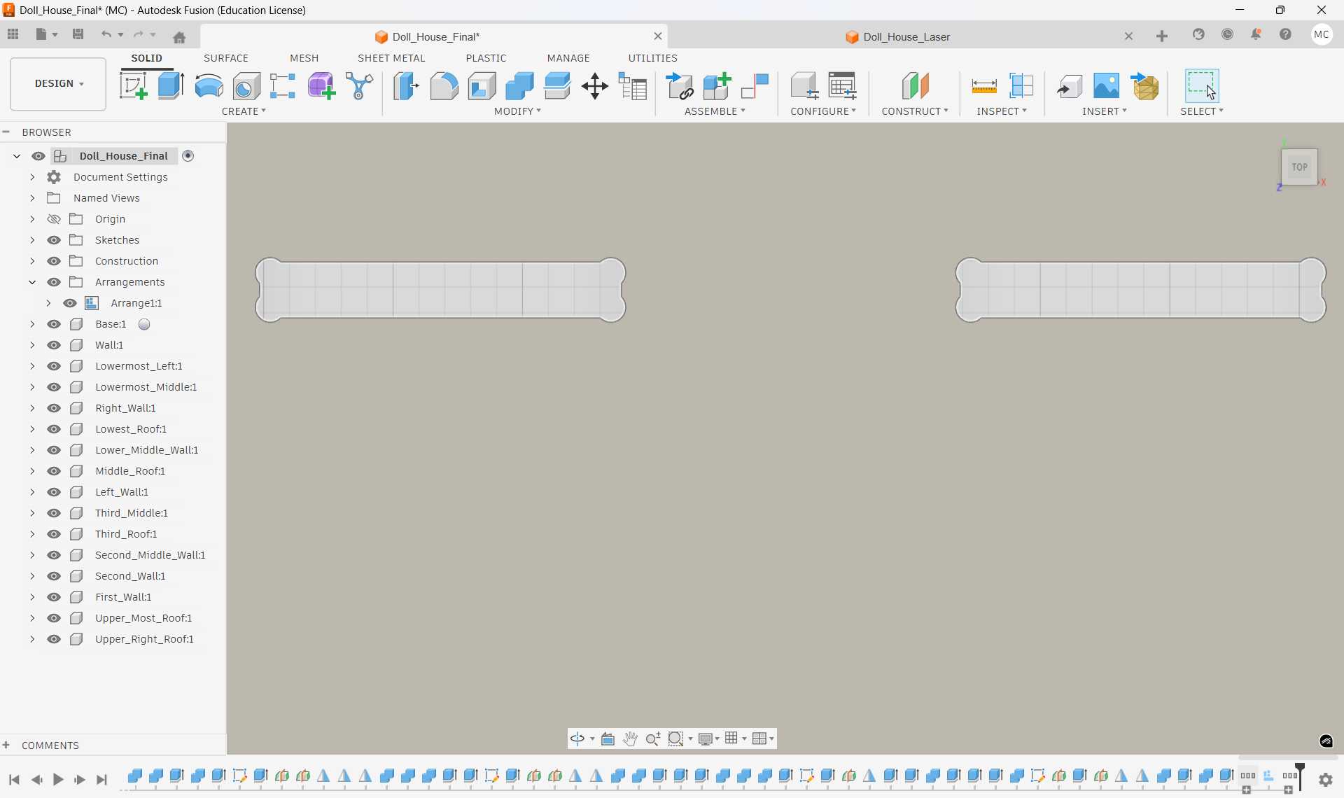
Final layout, all panels scaled and arranged flat, ready for export.
Step 8: Adding Dogbone Fillets, Nifty Dogbone Add-In
A CNC router bit is cylindrical, which means it cannot cut a perfectly sharp internal corner, it always leaves a small radius equal to half the bit diameter. When press-fit joints slot together, these rounded corners prevent the mating panel from seating fully, leaving a gap. The solution is to add dogbone fillets: small circular cutouts placed at each internal corner so the mating edge clears the radius and the joint fits flush.
Rather than adding these manually, the Nifty Dogbone add-in for Fusion 360 automates this process across all selected bodies at once.
Installing the Add-In
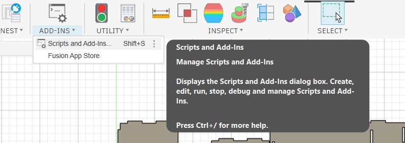
The add-in was accessed via the Utilities tab → ADD-INS → Fusion App Store.
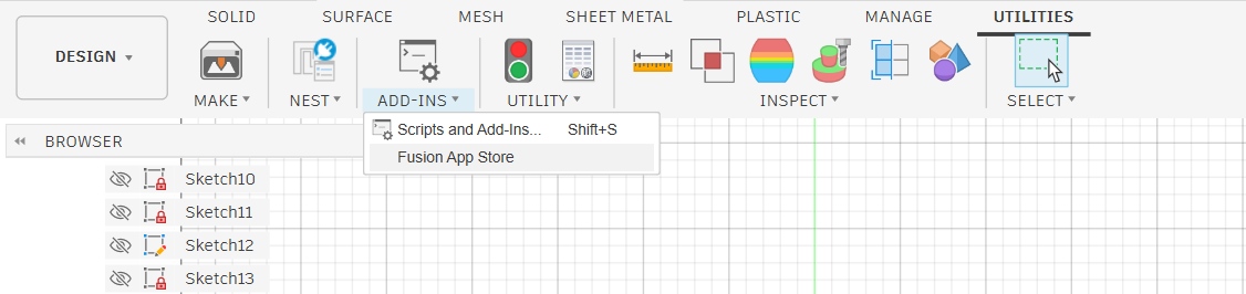
Utilities tab → ADD-INS → Fusion App Store to browse available add-ins.
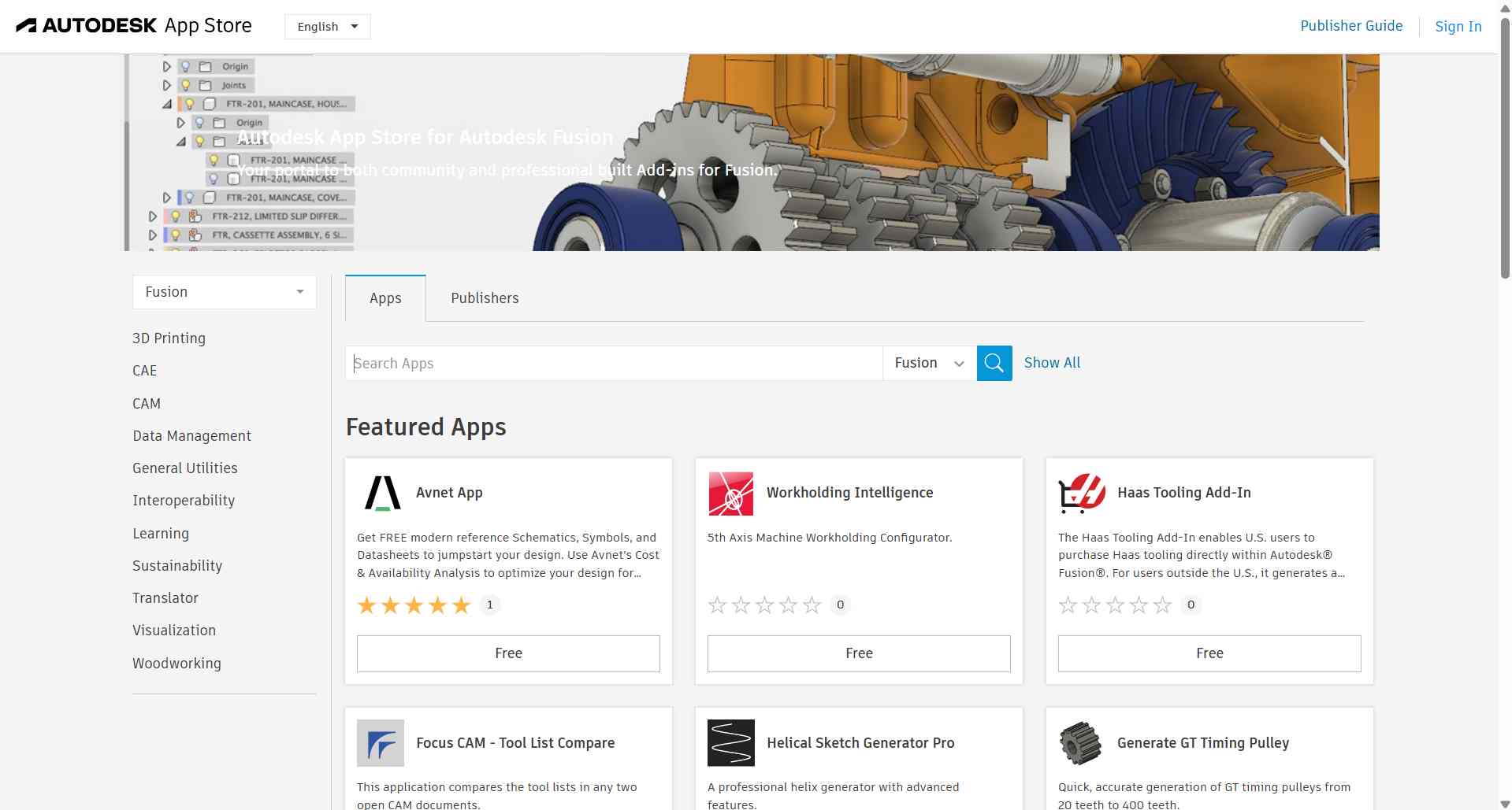
Autodesk App Store for Fusion 360, a library of community and professional add-ins.
Searching for "nifty" in the App Store returned the Nifty Dogbone for Autodesk Fusion add-in.
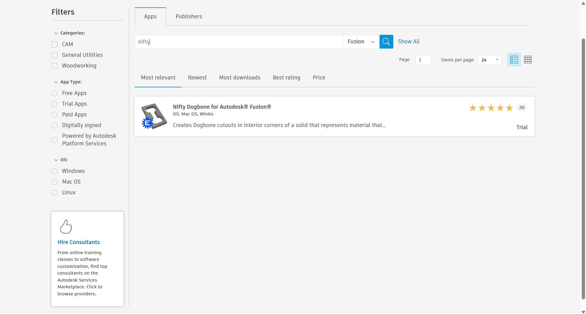
Search result for "nifty", Nifty Dogbone add-in found.
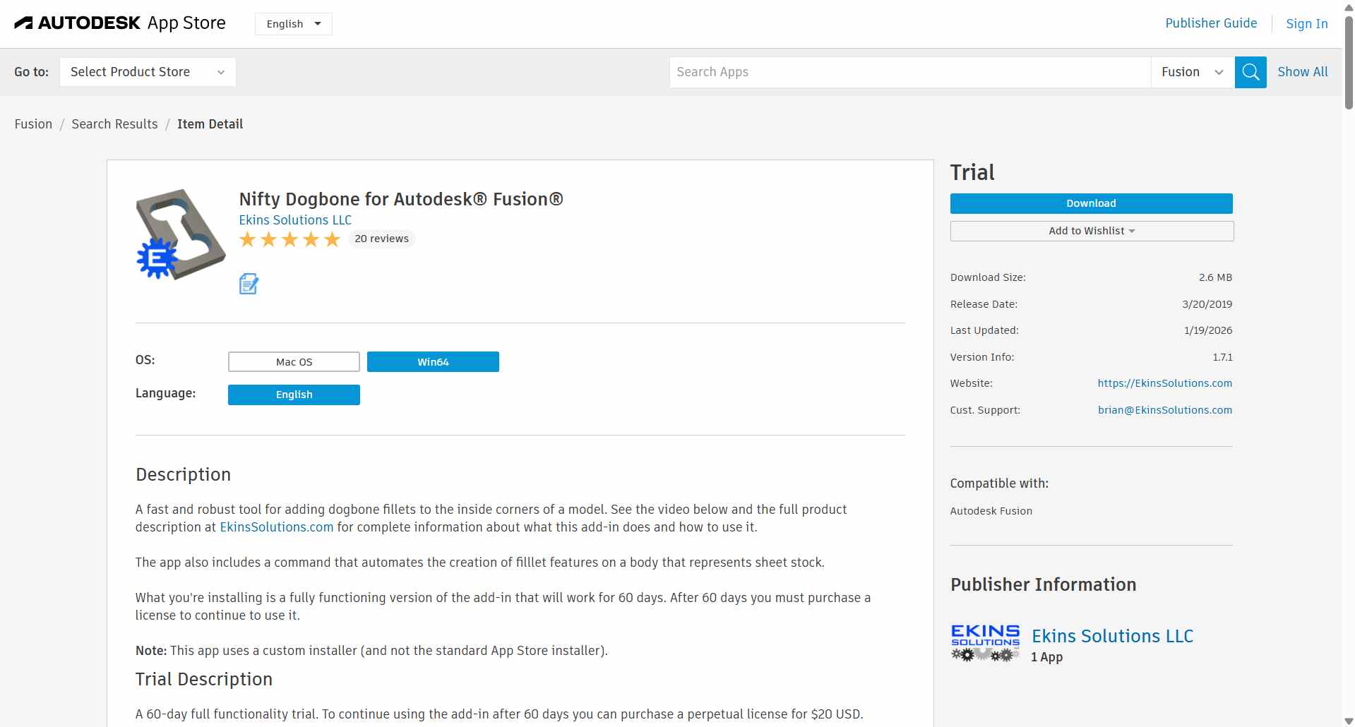
Nifty Dogbone detail page, a fast and robust tool for adding dogbone fillets to internal corners. Available as a 60-day free trial.
After downloading, the add-in was enabled in Fusion 360 via ADD-INS → Scripts and Add-Ins (Shift+S).
ADD-INS → Scripts and Add-Ins opens the dialog to manage all installed add-ins.
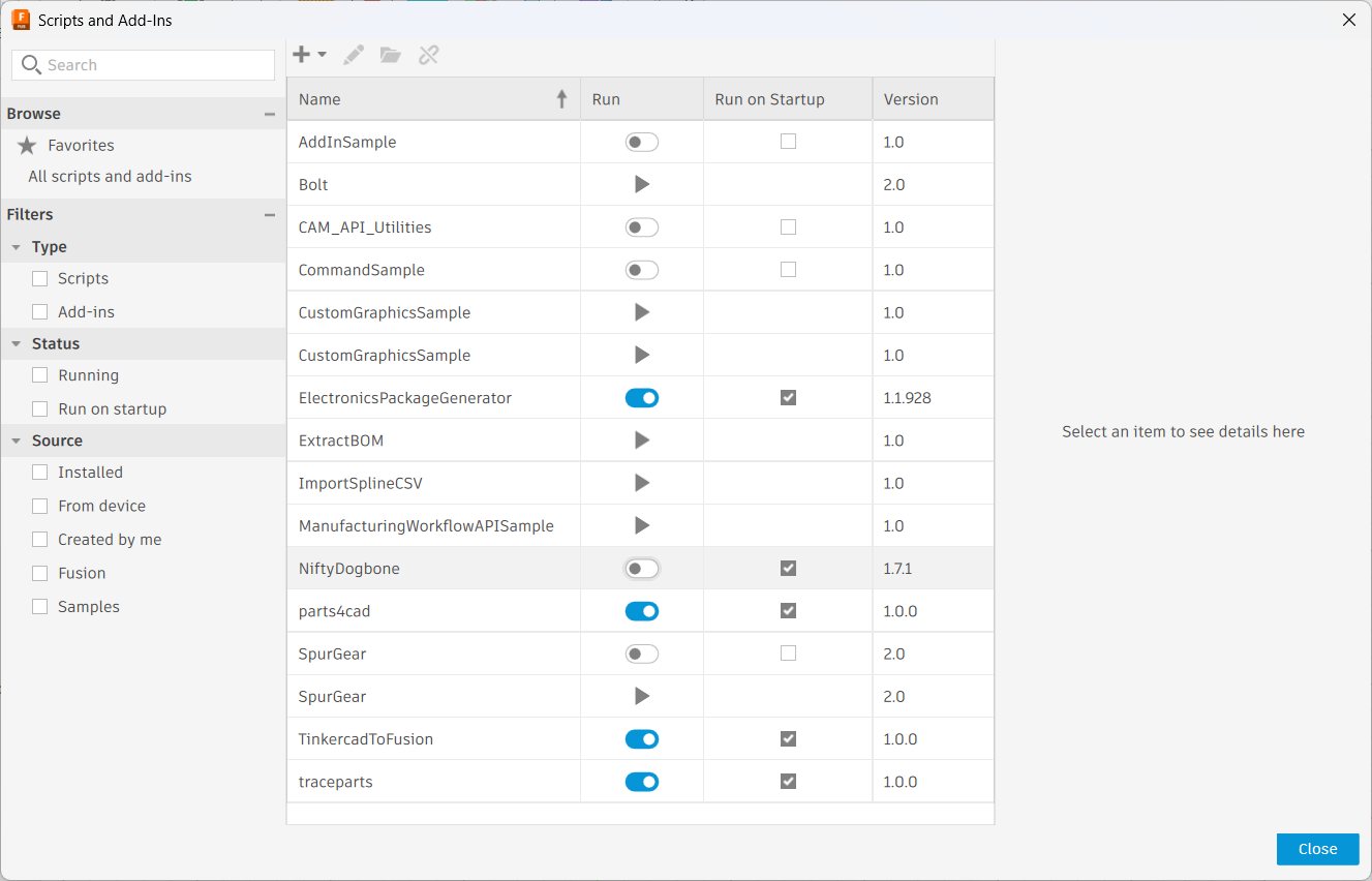
Slide the toggle to the right to enable the add-in.
Applying Dogbone Fillets
Once installed, the Nifty Dogbone command appeared in the Modify menu. It was applied to all 16 panel bodies simultaneously, the tool diameter was set to 6.00 mm to match the CNC router bit, with 0.025 mm additional clearance for a clean fit.
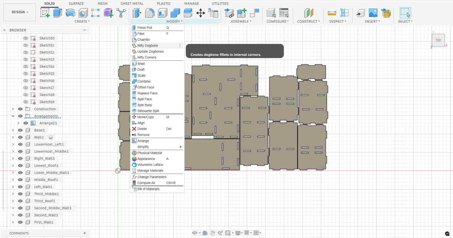
Nifty Dogbone available in the Modify menu — tooltip confirms it creates dogbone fillets in internal corners.
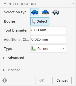
Nifty Dogbone dialog — Tool Diameter: 6.00 mm, Additional Clearance: 0.025 mm, Type: Corner.
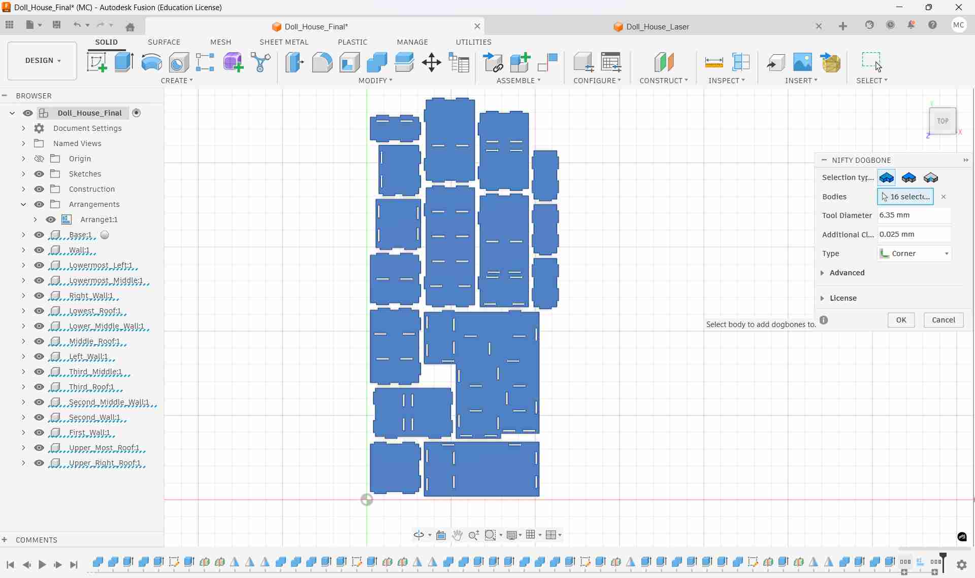
All 16 panel bodies selected — dogbone fillets applied to every internal corner across the full layout.
Dogbone result — circular corner reliefs visible on each internal corner, ensuring mating panels will seat flush.
Step 9: Final Arrange & DXF Export
Ungrounding Components for Re-Arrangement
Before running the final Arrange, the base component was checked for its grounding state.
In Fusion 360, a grounded component is locked in place and cannot be moved by the Arrange function. To allow all panels to be repositioned freely, the base component was ungrounded by right-clicking it in the browser and selecting Unground From Parent.
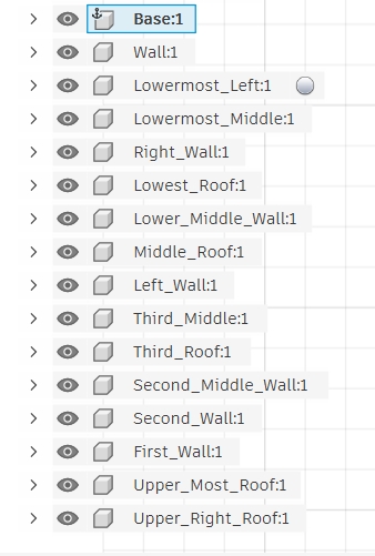
Base:1 shown with the ground anchor icon — component is locked in place.
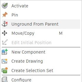
Right-click → Unground From Parent frees the component for re-arrangement.
Running the Final Arrange
With all components free, the Arrange function was run again with the exact standard sheet dimensions: 8 ft × 4 ft (1219.2 mm × 2438.4 mm) — the industry-standard plywood sheet size. The solver was set to 2D True Shape to achieve efficient nesting of the actual panel outlines rather than bounding boxes. Frame width was set to 20 mm and object spacing to 12 mm.
Arrange Envelopes tab
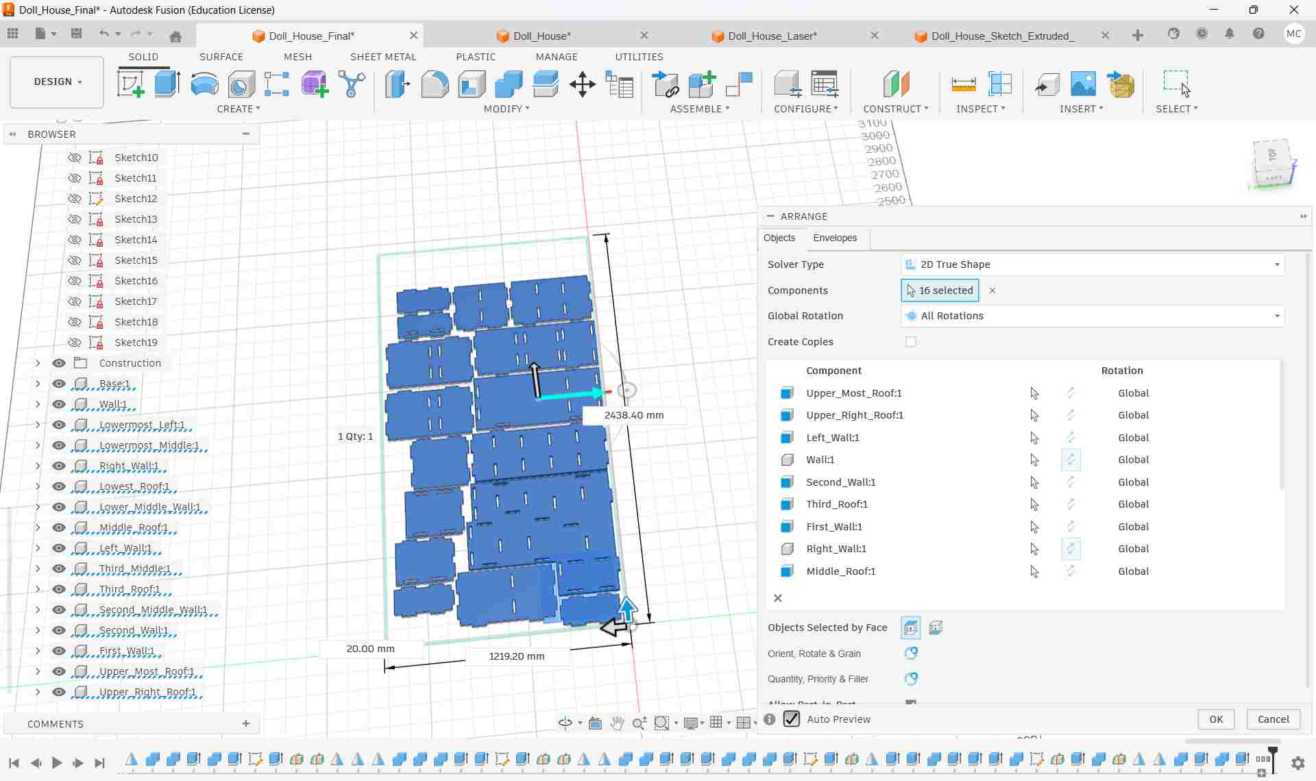
rrange Objects tab — 16 components selected
Project Sketch & Export DXF
A new sketch was created on the XY plane and all panel body edges were projected onto it using Sketch → Project/Include → Project. This converts the 3D solid outlines into 2D sketch curves, capturing the exact cut geometry including all joint notches and dogbone fillets.
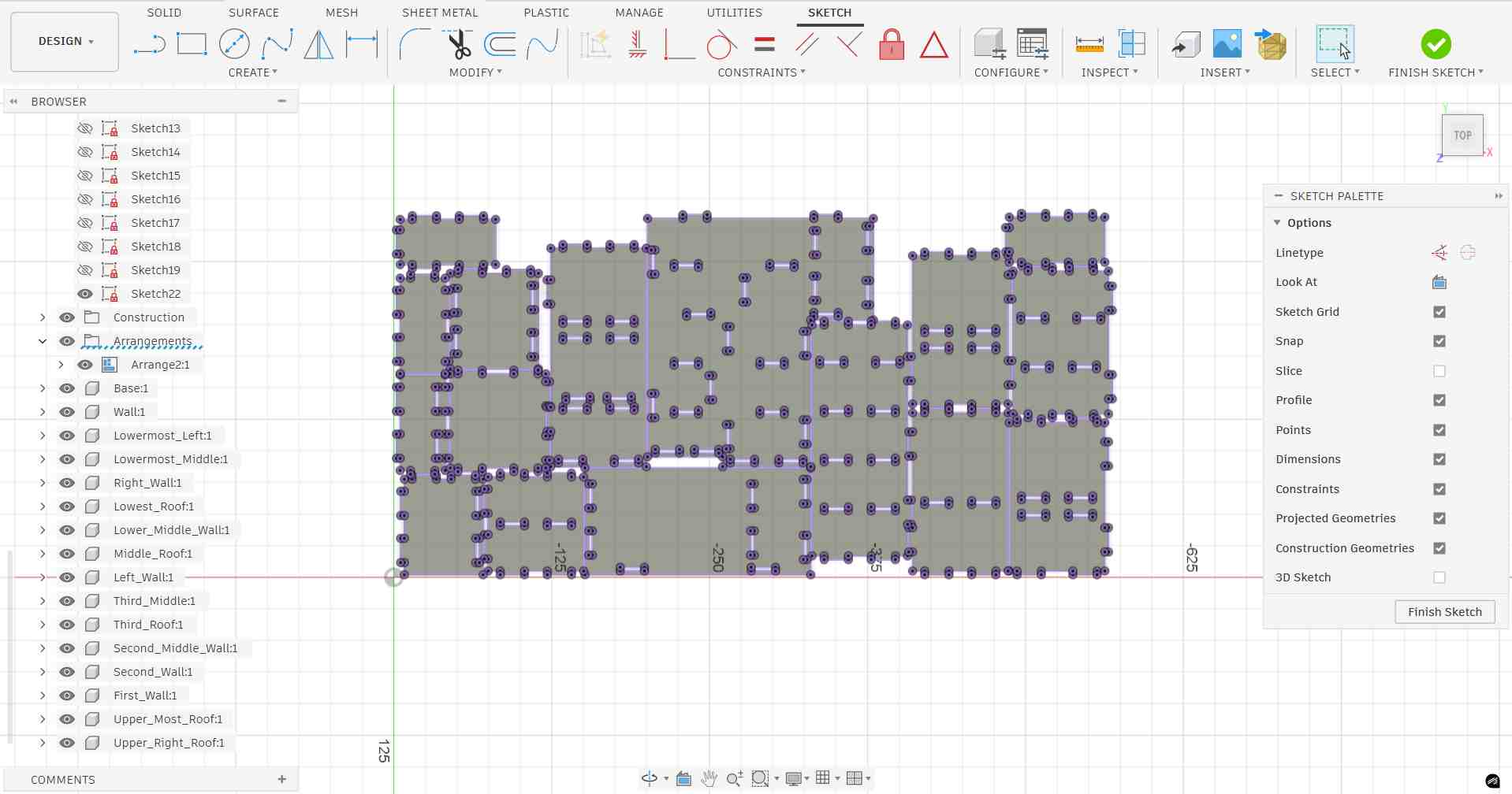
Projected sketch — all 16 panel profiles including joint notches and dogbone fillets projected as 2D curves.
The sketch was then right-clicked in the browser and Export DXF was selected. This saves the complete flat layout as a DXF file, which is the standard format for importing cut geometry into CAM software such as VCarve or Aspire for CNC toolpath generation.
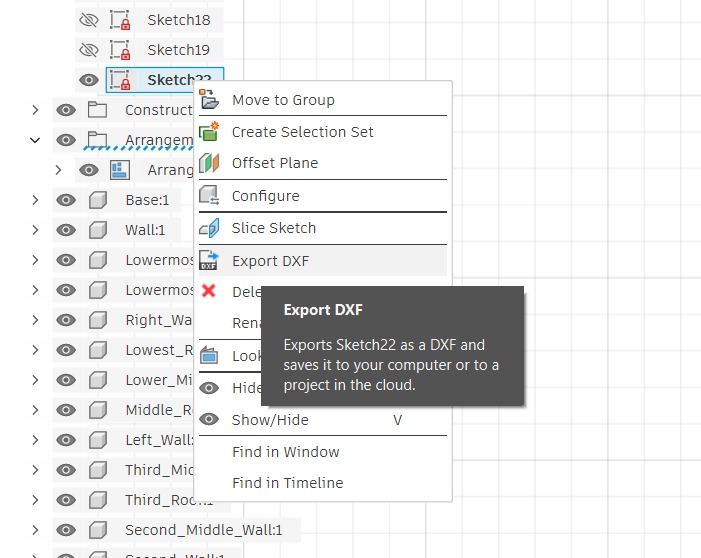
Right-click on the projected sketch → Export DXF — saves the complete panel layout for CAM import.
Step 9: Inkscape — Preparing the SVG for CNC Cutting
With the SVG exported from Fusion 360, it was opened in Inkscape to clean up the geometry, verify dimensions, and assign line properties.
1. Import & Resize Canvas
The SVG was opened in Inkscape. All objects were selected with Ctrl+A, then the canvas was resized to fit the selection via File → Document Properties → Resize page to drawing or selection (Shift+Ctrl+R). This removes any extra whitespace so the document boundary matches the actual geometry exactly.
Shift + Ctrl + R — Resize page to drawing or selection
2. Verify Scale & Dimensions
Each panel was selected individually and its dimensions were checked in the toolbar to confirm they matched the Fusion 360 design values. The document units were confirmed as millimeters in File → Document Properties to prevent any scaling errors when the file is imported into CAM software.
Panel dimensions checked in the toolbar — values match Fusion 360 parametric design.
3. Assign Stroke Colors for Cut Operations
Line colors are used by the CAM software to distinguish between different cutting operations. Using Object → Fill and Stroke (Shift+Ctrl+F), stroke colors were assigned and fill was set to None for all paths.
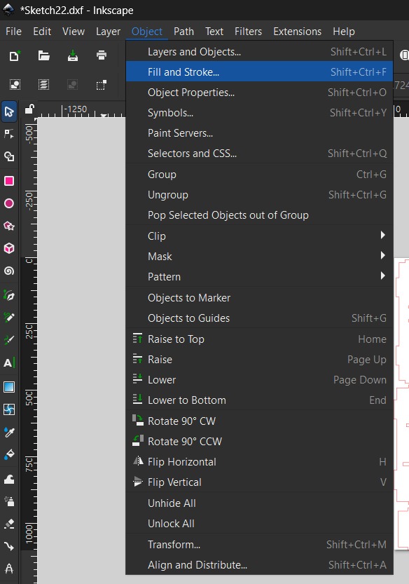
Object --> Fill and Stroke
All cut lines were given a stroke width of 0.1 mm (hairline). This ensures the CAM software recognises them as vector cut paths rather than filled areas, and prevents any offset being applied to the line thickness during toolpath calculation.
No fill applied,only stroke paths will be recognised by CAM software.
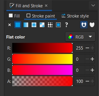
Max value added to Red color in RGB
Profile / Through Cuts — Red
- Outer boundary cuts and slot profiles
- Stroke: R=255, G=0, B=0
- Fill: None
Pocket / Partial Cuts — Black
- Engraving or pocket operations
- Stroke: R=0, G=0, B=0
- Fill: None
Stroke width set to 0.1mm
6. Save as SVG for CAM Software
The completed file was saved as a plain SVG (File → Save As → Plain SVG). Plain SVG strips Inkscape-specific metadata, ensuring maximum compatibility when the file is imported into VCarve or other CAM software for toolpath generation.
Laser Test Cut Result
After exporting the scaled SVG, the file was sent to the laser cutter to produce a physical test model from cardboard. This low-cost test confirmed that all press-fit joints align correctly and the panels assemble without gaps before committing to the full-size CNC cut in plywood.
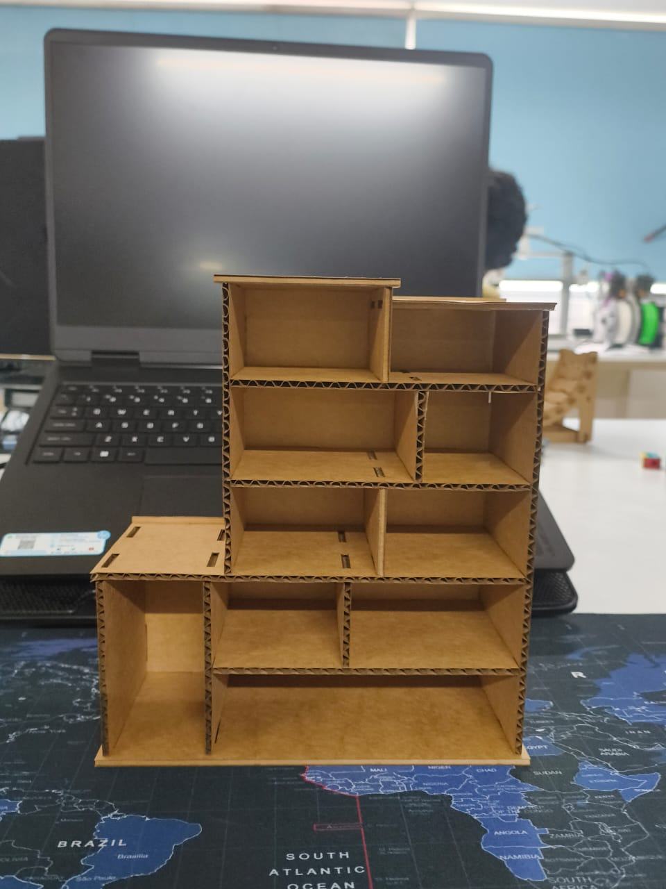
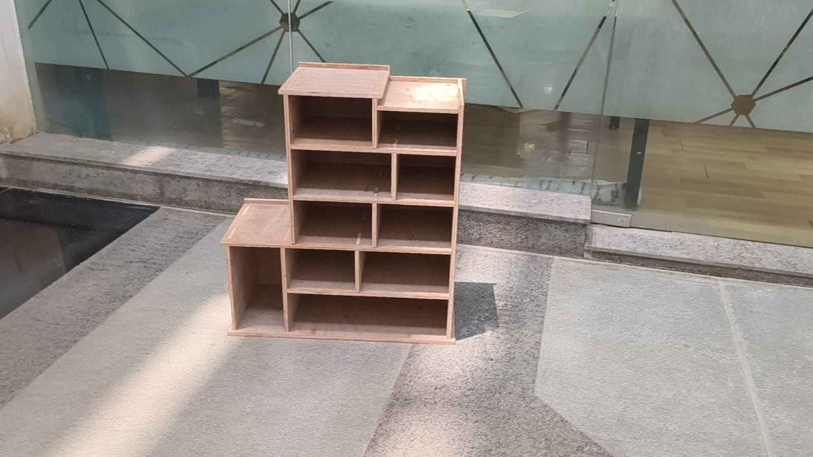
Assembled laser test cut model — all panels interlock via press-fit joints with no fasteners or glue, confirming the design is ready for full-scale CNC cutting.
Step 10: VCarve Pro — CAM Setup
With the DXF file verified, it was imported into VCarve Pro (ShopBot Edition) — the CAM software used at FabLab Kochi to generate toolpaths for the ShopBot CNC router. VCarve translates the 2D vector geometry into machine instructions (G-code) by defining cut depths, tool diameters, feed rates, and toolpath strategies.
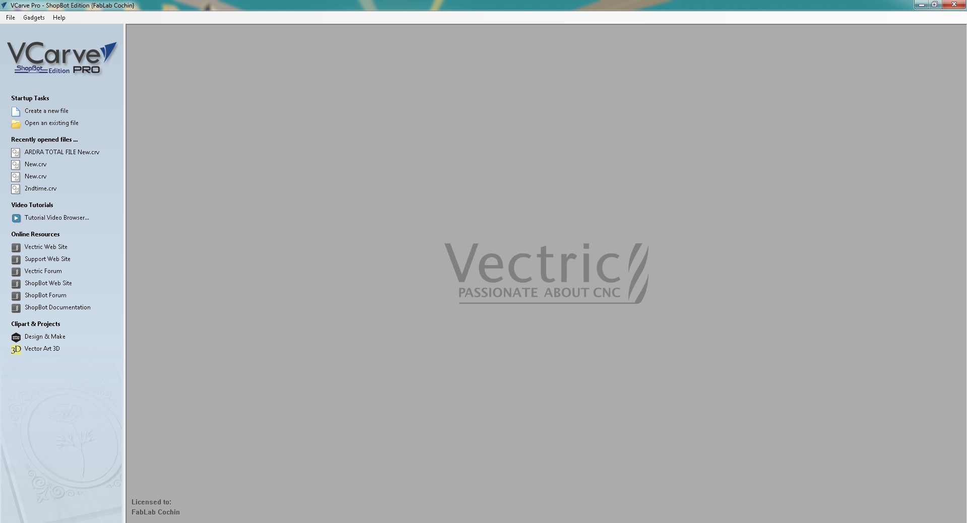
VCarve Pro (ShopBot Edition) — the CAM software used at FabLab Kochi for CNC toolpath generation.
A new file was created via Create a New File, which immediately opens the Job Setup dialog. This is where the sheet dimensions and material properties are configured before any toolpaths are defined.
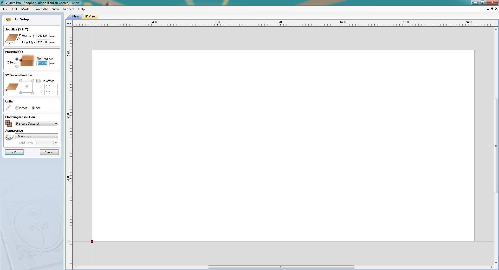
Job Setup in VCarve — sheet size 2438 × 1219 mm, material thickness 12.228 mm, units in mm.
2. Set Material Thickness
The plywood sheet thickness was measured and entered as 12.228 mm. And click 'Ok'.
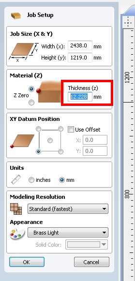
Material thickness field set to 12.228 mm — measured from the actual plywood sheet.
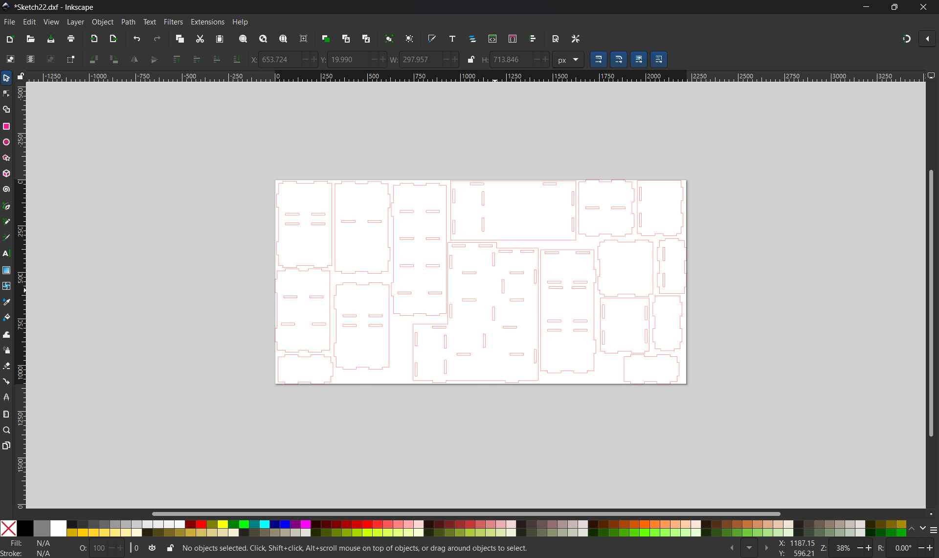
Clicking OK confirmed the job settings and opened the 2D drawing workspace. The canvas displays the sheet boundary as a white rectangle scaled to the configured dimensions, with the tool panels loaded on the left and the Job Dimensions confirmed at the bottom left of the screen.
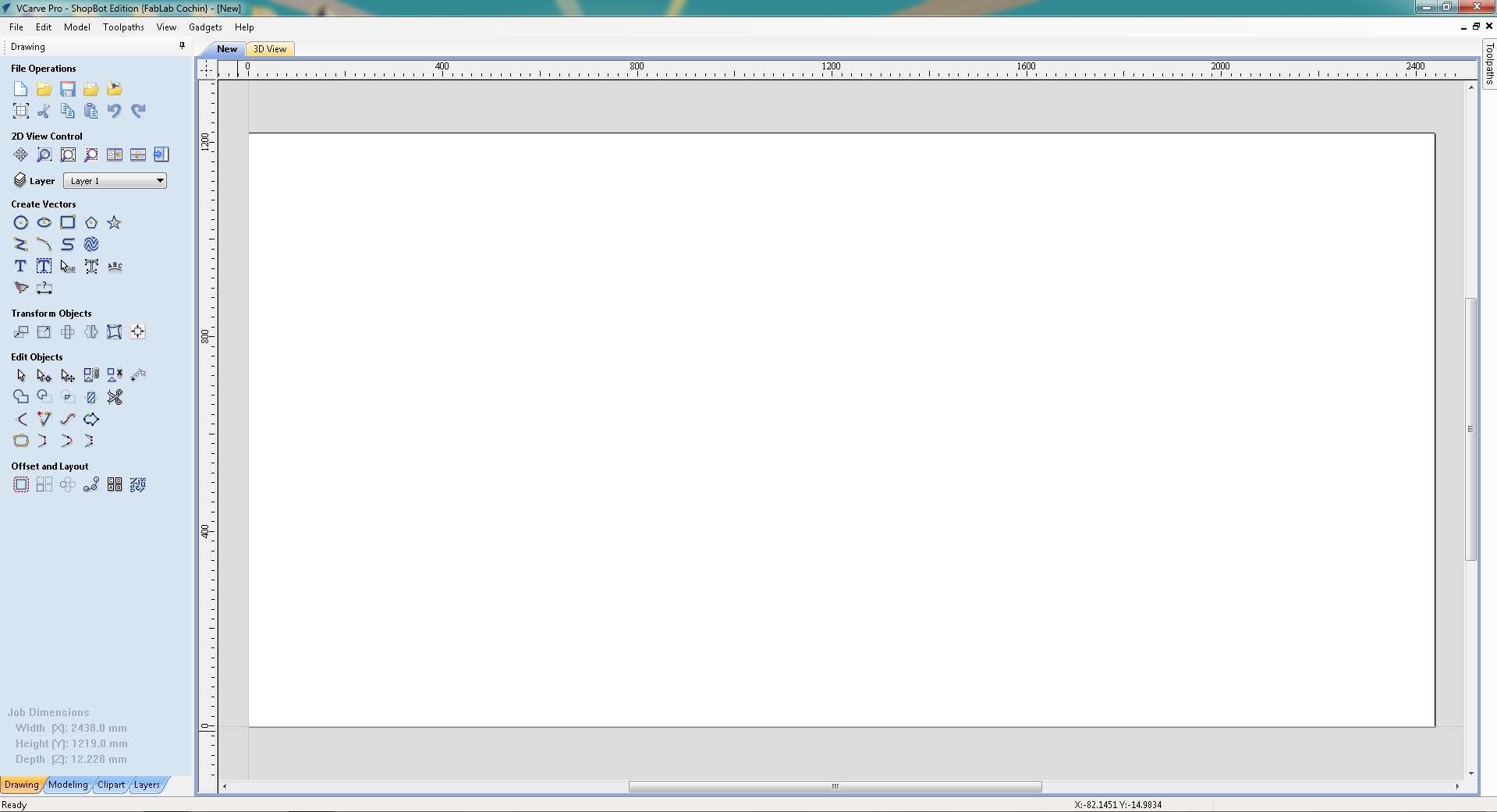
Empty 2D workspace after Job Setup confirmed, sheet boundary (2438 × 1219 mm) and material depth (12.228 mm) shown in the Job Dimensions panel at the bottom left, ready for vector import.
3. Import the DXF File
The DXF exported from Fusion 360 was imported via File → Import → Import Vectors. This brings all the panel outlines including joint notches and dogbone fillets into the VCarve workspace as editable vector paths ready for toolpath assignment.
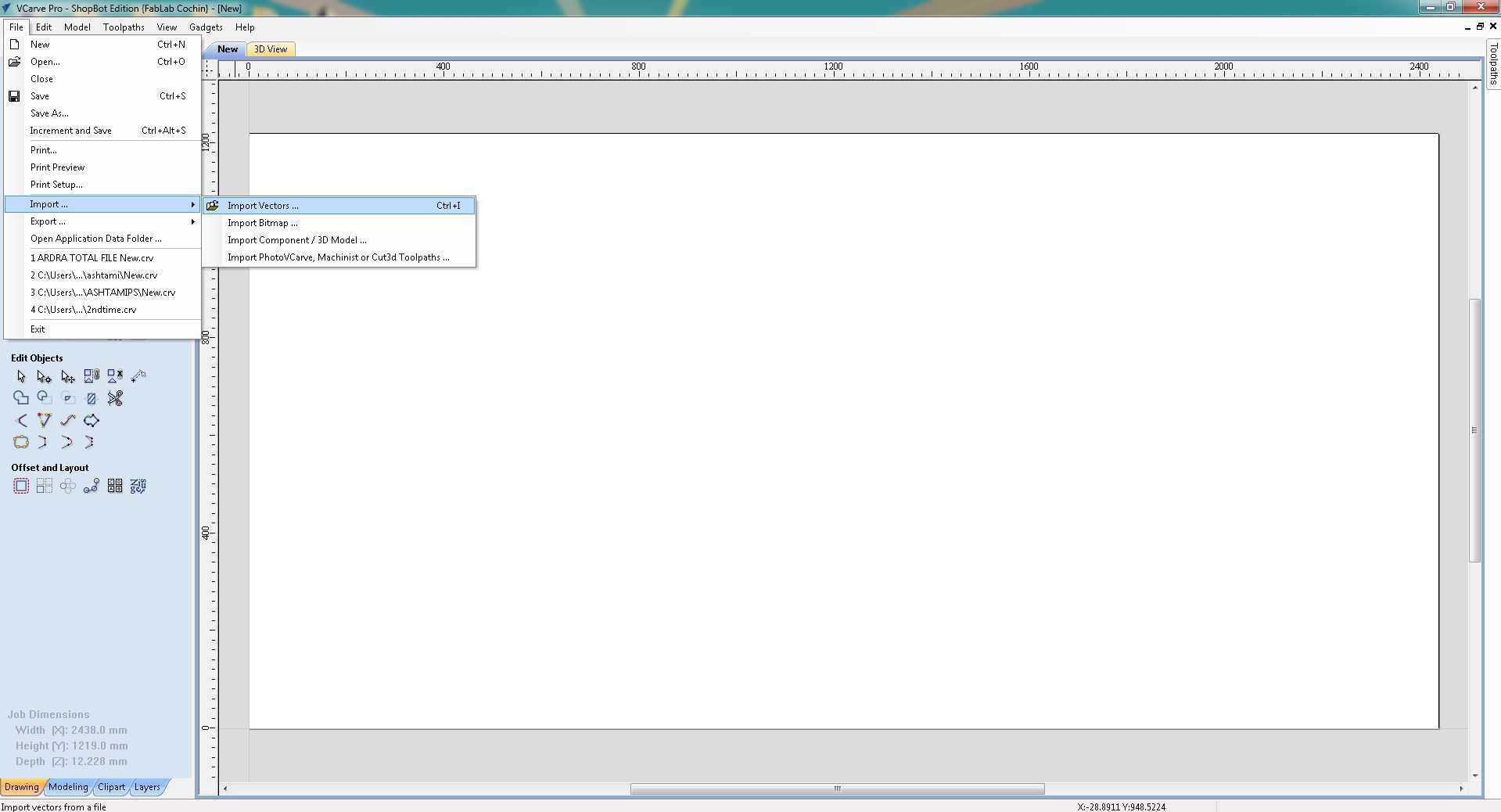
File → Import → Import Vectors, used to bring the DXF file into VCarve.
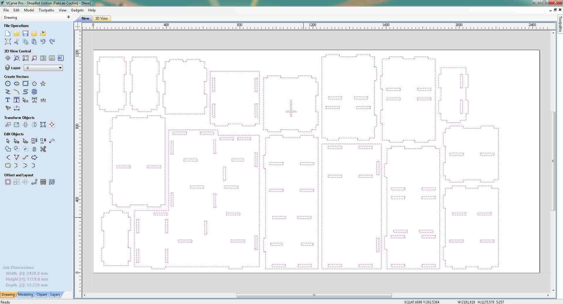
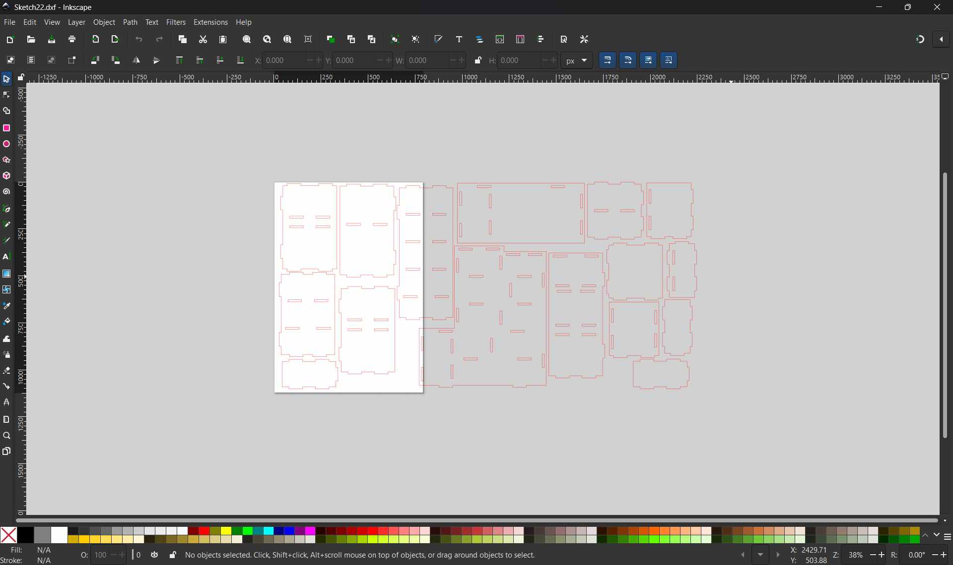
All 16 doll house panels imported, panel outlines, joint notches, and dogbone fillets visible across the full sheet.
4. Review Imported Vectors
This is the toolbar in VCarve Pro. This containes all the tools needed to edit the vectors, like moving the vectors, joining the vectors,dding drill holes etc
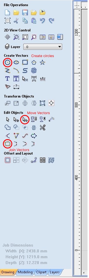
Vcarve toolbar
The full sheet was reviewed in the 2D workspace to verify all panels were correctly positioned. Each panel was individually checked by selecting it, VCarve highlights the selected vector with a dashed outline, making it easy to identify individual parts among the full set.
One panel selected (dashed outline), verifying individual vectors within the full imported layout.
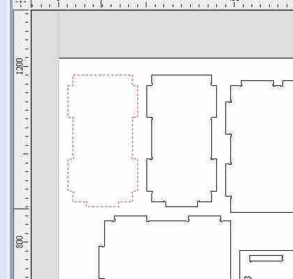
Close-up of the selected panel, pink dashed outline highlights the individual vector.
5. Fix Open Vectors
During review, VCarve flagged an open vector, a path where the start and end points do not connect, shown as a pink dashed line.
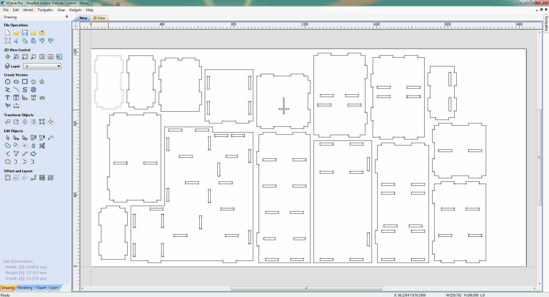
Open vectors cannot be assigned profile toolpaths; they were closed using the Edit → Join Open Vectors tool before proceeding.
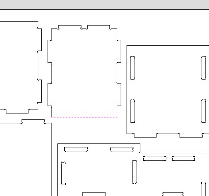
Open vector flagged by VCarve (pink dashed line), must be closed before toolpath assignment.
6. Set Up Toolpaths
With vectors verified and closed, the Toolpaths panel was opened from the right sidebar.
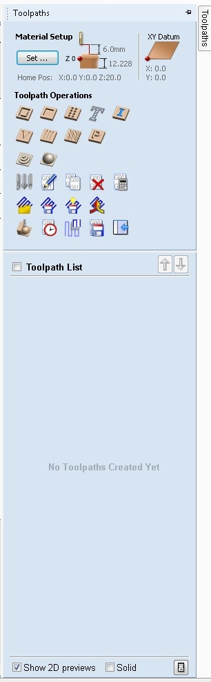
Toolpaths panel, material setup confirmed, no toolpaths created yet.
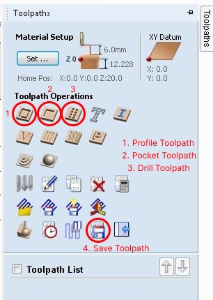
Toolpath Operations
7. Create Drilling Toolpath
For dowel holes, a Drilling Toolpath was created. Circles of 6 mm diameter were drawn using Draw Circle to define the drill positions, then selected as the vector input for the toolpath.
The tool used was a Fab End Mill (6 mm, single flute), with a cut depth of 4.5 mm.
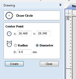
Draw Circle, 6 mm diameter circles drawn to define drilling positions.
Then I clicked the Drilling Toolpath button in the Toolpaths panel.
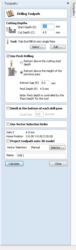
Drilling Toolpath, 6 mm end mill, 4.5 mm cut depth, peck drilling retract enabled.
With the drilling toolpath dialog configured, the 6 mm circles placed across the sheet served as the vector input, VCarve reads their center points to determine each drill plunge location.
The image below shows the full sheet with all drill positions marked before the toolpath is applied.
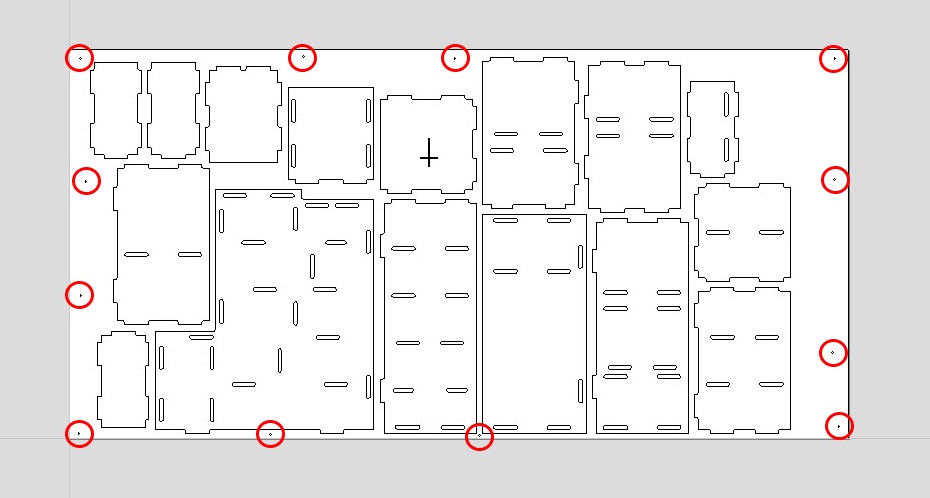
Full sheet layout, red circles mark all 6 mm drill positions for dowels and screws across every panel.
Then I checked the toolpath in the 3D View window.
3D material view, sheet dimensions (2438 × 1219 × 12.228 mm) confirmed before running the toolpath simulation.
The Fab End Mill (6 mm, single flute) was configured with the following cutting parameters for the drilling operation:
- Pass Depth: 4.5 mm
- Stepover: 4.8 mm (80%)
- Spindle Speed: 12,000 RPM
- Feed Rate: 1200.2 mm/min
- Plunge Rate: 1200.0 mm/min
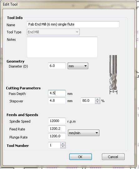
Edit Tool dialog, Fab End Mill (6 mm, single flute) configured for the drilling operation.
After selecting all the drill circles and calculating the toolpath, VCarve generated Drill 1. The toolpath preview panel confirms the cutting parameters and shows an estimated run time of 1 min 39 sec for all drill holes on the sheet.
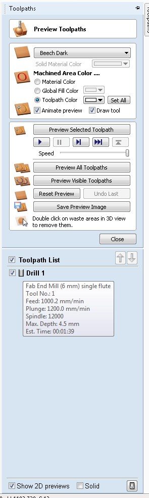
Drill 1 toolpath confirmed in the preview panel, feed 1000.2 mm/min, plunge 1200.0 mm/min, spindle 12000 RPM, max depth 4.5 mm, estimated time 1 min 39 sec.
8. Create Profile Toolpath for Slots
With the drilling toolpath saved, the finger joint slots were selected next.
A Profile Toolpath was created for these, cutting on the inside of the slot vectors to produce the interlocking joints.
The 2D view below shows the sheet with all toolpaths applied, drilling holes and profile cuts visible across every part.
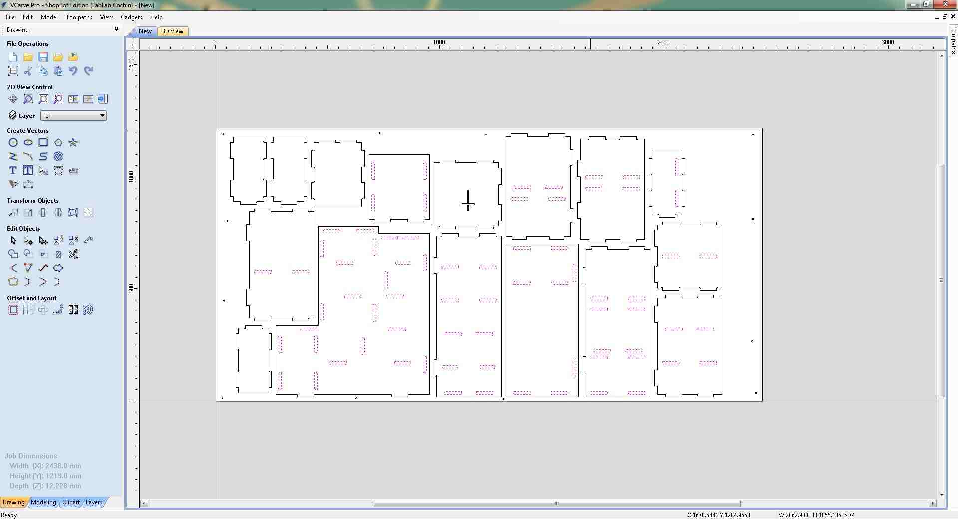
2D sheet view with all toolpaths applied, drilling paths at hole positions and profile paths along all slot outlines and part perimeters.
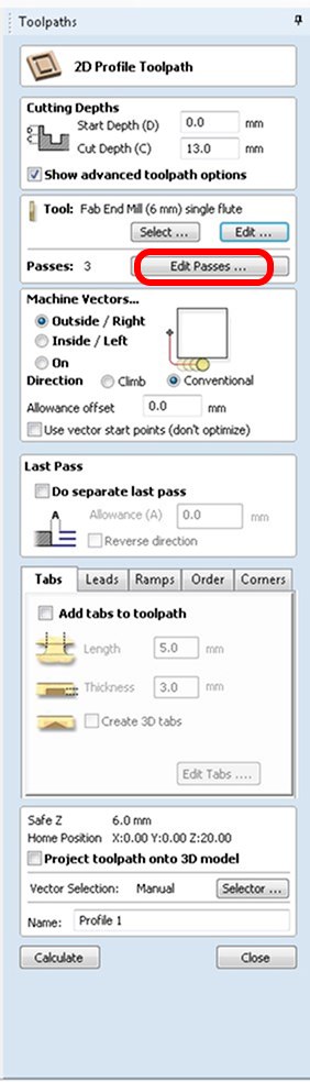
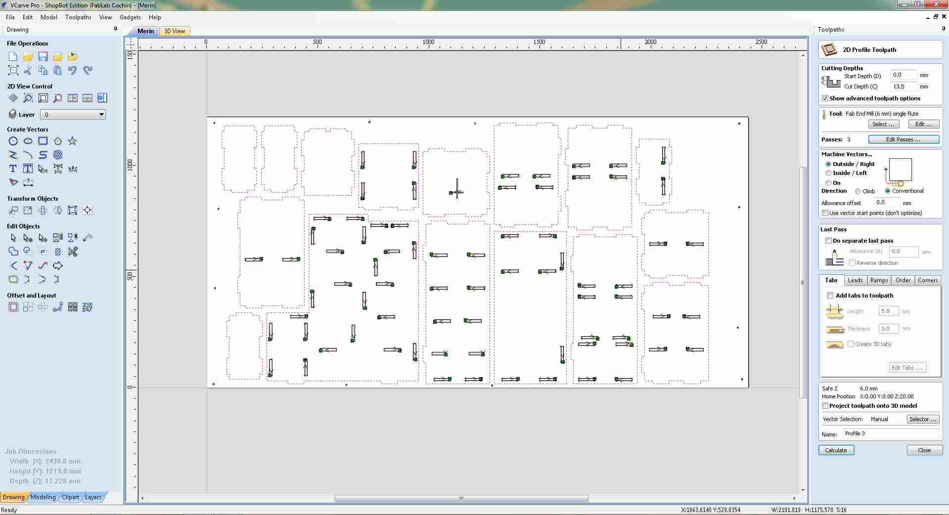
2D Profile Toolpath dialog, 13.0 mm cut depth, Outside/Right, 3 passes, named Profile 1.
Clicking Edit Passes opened the Specify Pass Depths dialog, where the number of passes and depth per pass were configured.
The total depth was set to 13.5 mm across 3 passes at 4.5 mm each (4.5 → 9.0 → 13.5 mm), stepping down evenly and staying within the tool's rated pass depth.
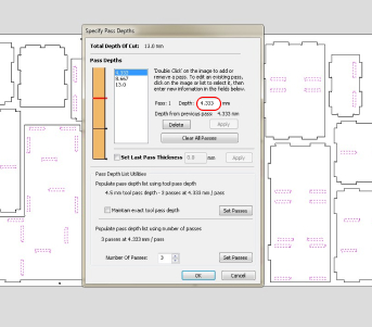
Initial pass depth configuration, 3 equal passes across 13.0 mm total depth.
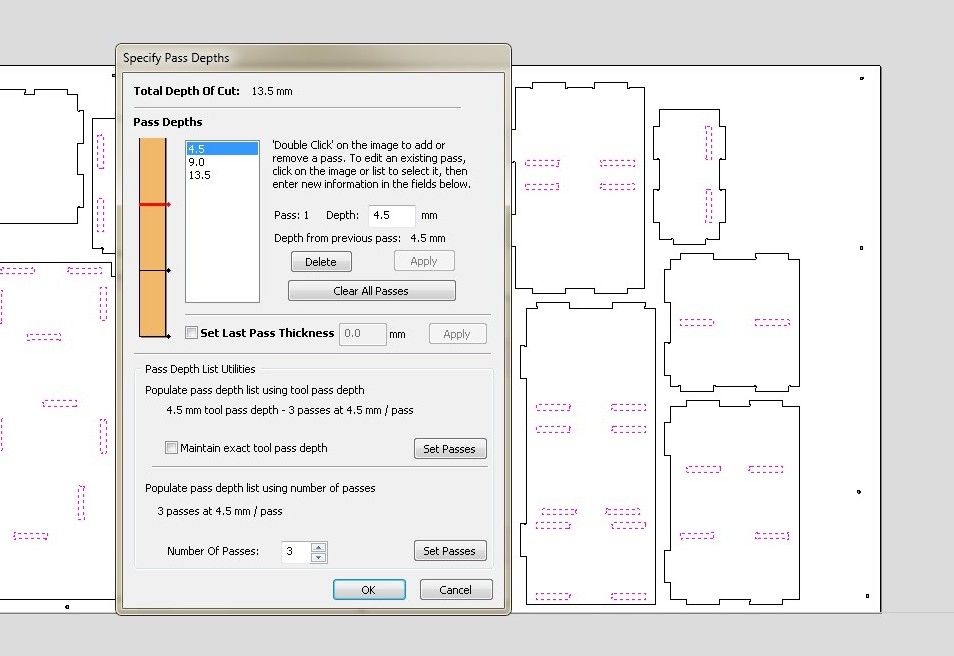
Final pass depths, 13.5 mm total, three passes at 4.5 mm each (4.5 → 9.0 → 13.5 mm).
Setting the cut depth to 13.5 mm, slightly beyond the material thickness of 12.228 mm, triggered a VCarve warning.
This is intentional: cutting fractionally past the sheet ensures clean, complete separation of all parts without leaving thin webs of uncut material. The CNC bed has a sacrificial spoilboard (MDF layer) beneath the workpiece specifically to absorb this small overcut without damaging the machine.
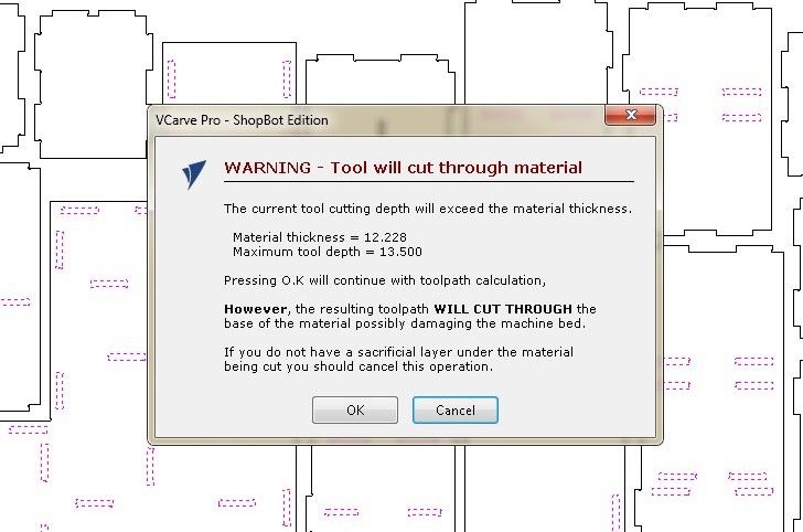
Cut-through warning, tool depth (13.5 mm) exceeds material thickness (12.228 mm). This is intentional; the sacrificial spoilboard underneath protects the machine bed. OK was clicked to proceed.
9. Preview Toolpaths in 3D Simulation
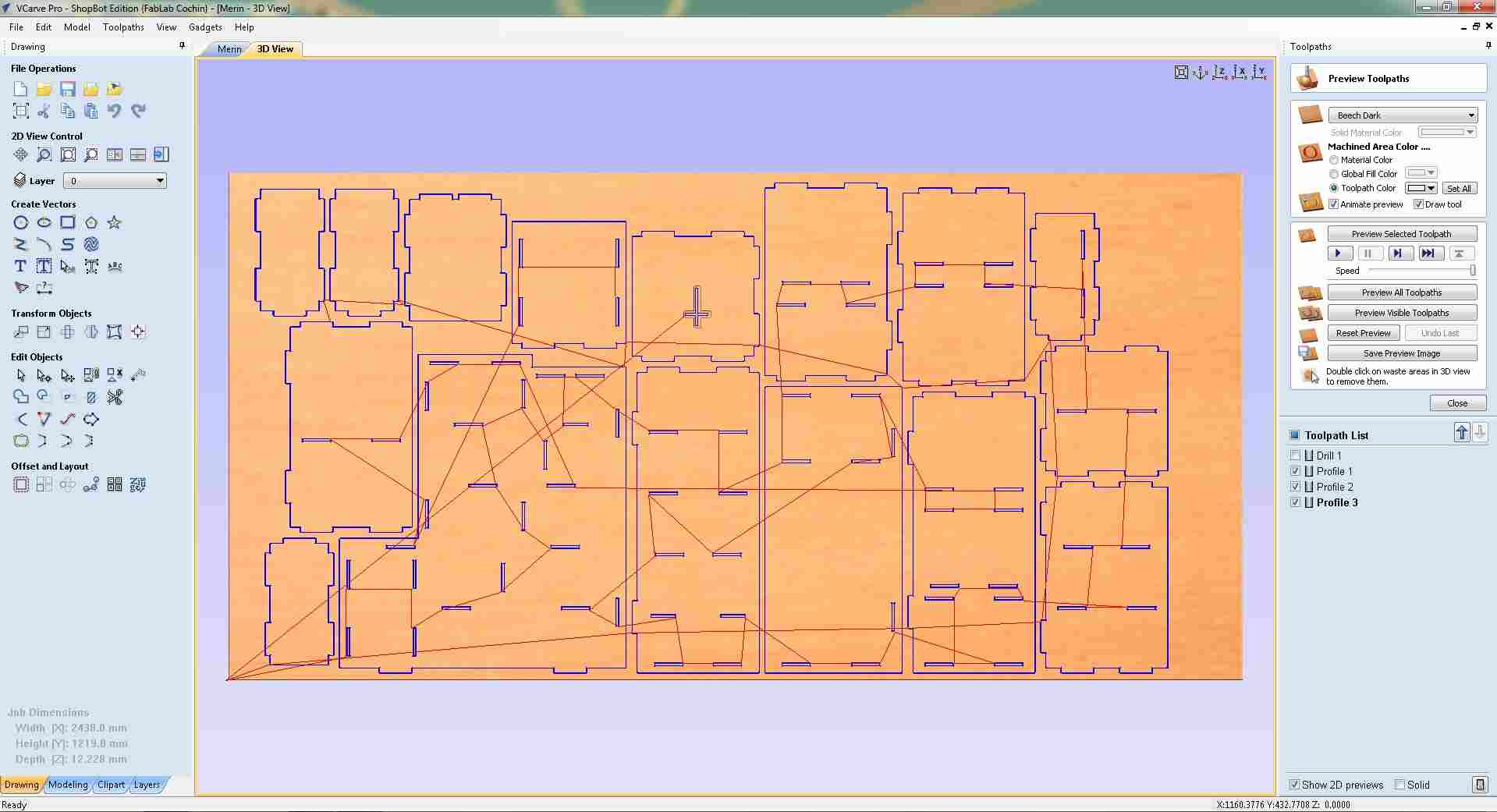
With both Drill 1 and Profile 1 toolpaths saved, the Preview All Toolpaths function was used to simulate the full cut on the 3D material view.
The simulation shows the routing paths traced across the plywood sheet, confirming that all part outlines, slots, and drill positions are correctly positioned before sending the file to the CNC machine.
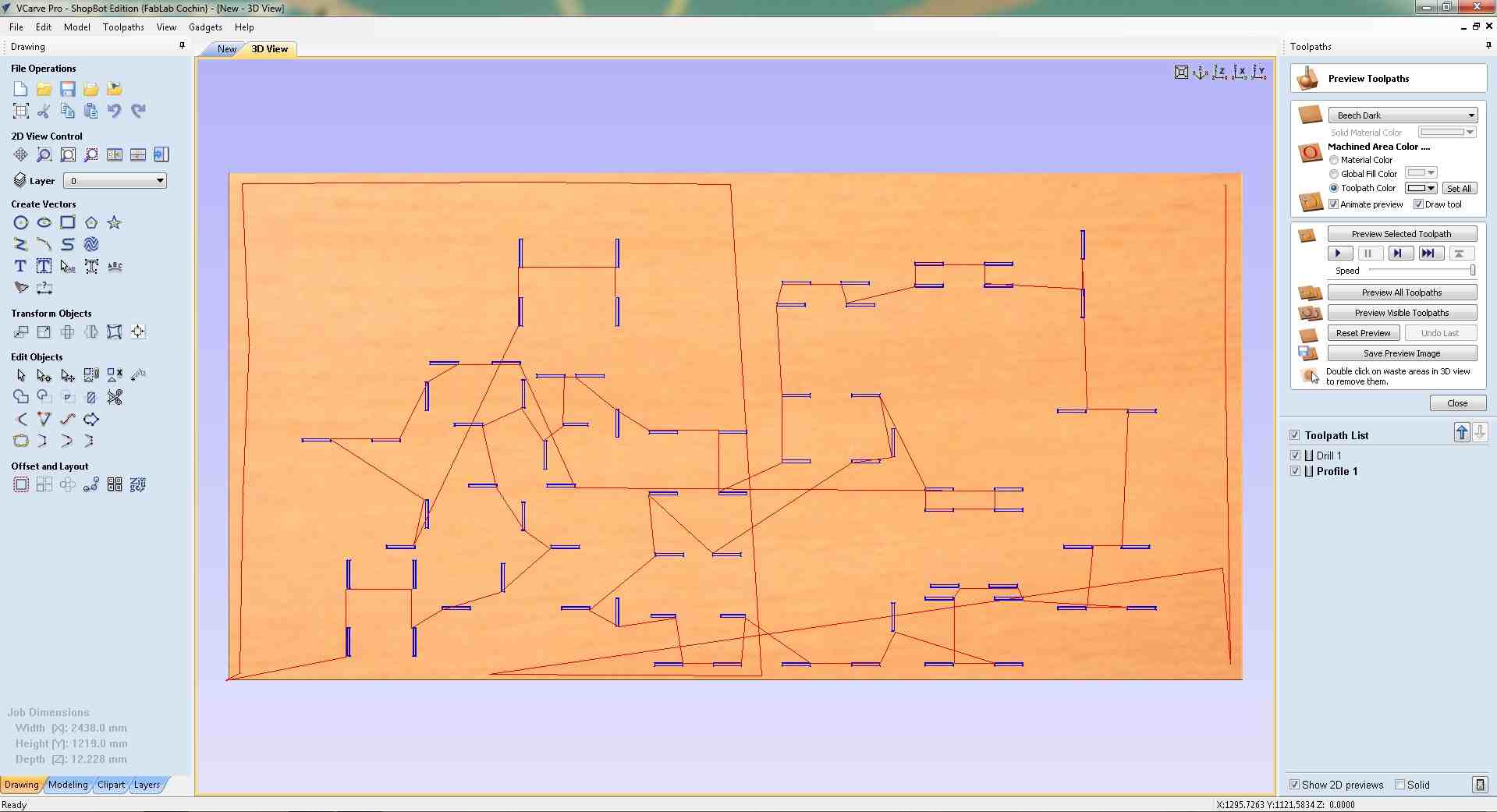
3D toolpath simulation, Drill 1 and Profile 1 paths traced across the full sheet, confirming correct placement of all cuts before sending to the ShopBot.
10. Create Engraving Toolpath for the Cross
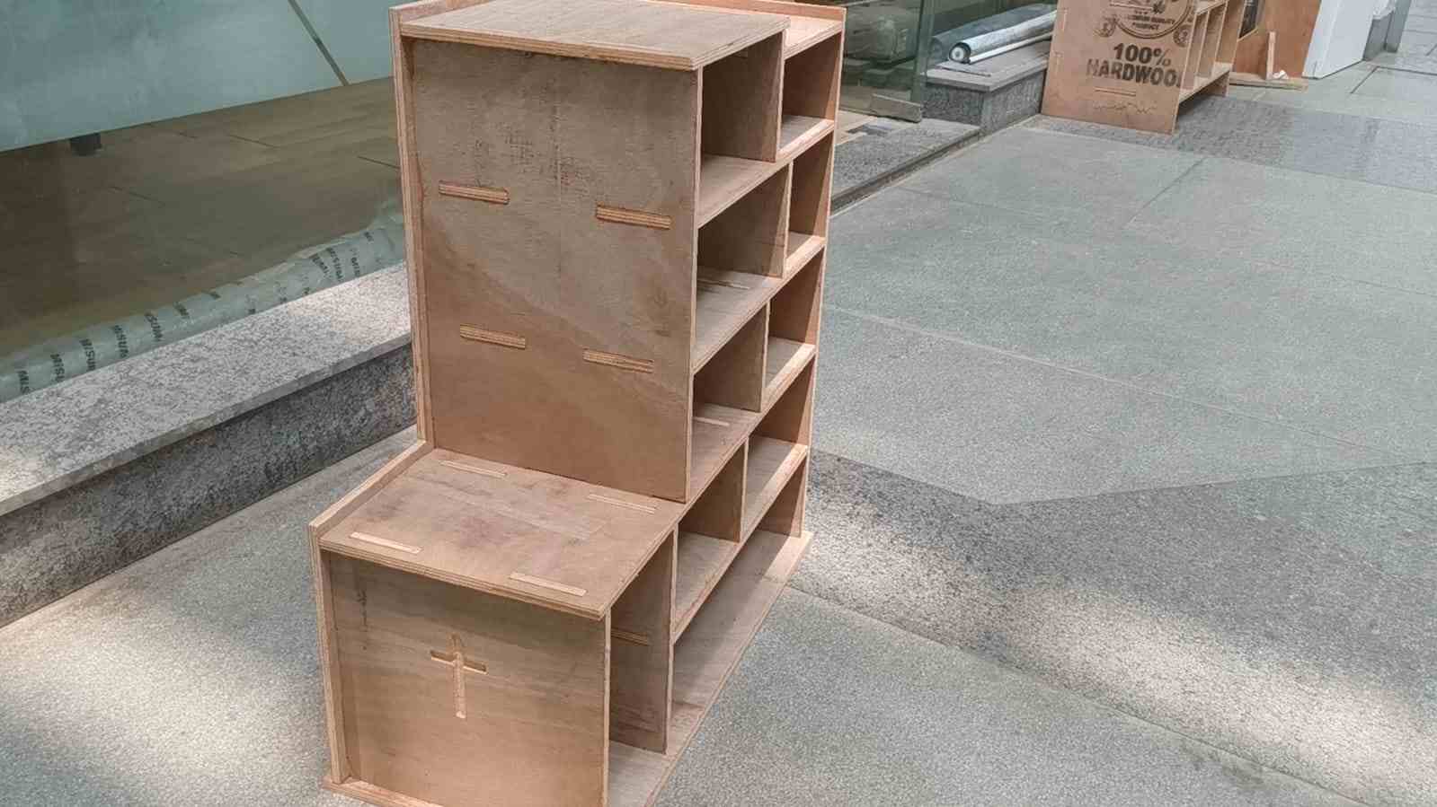
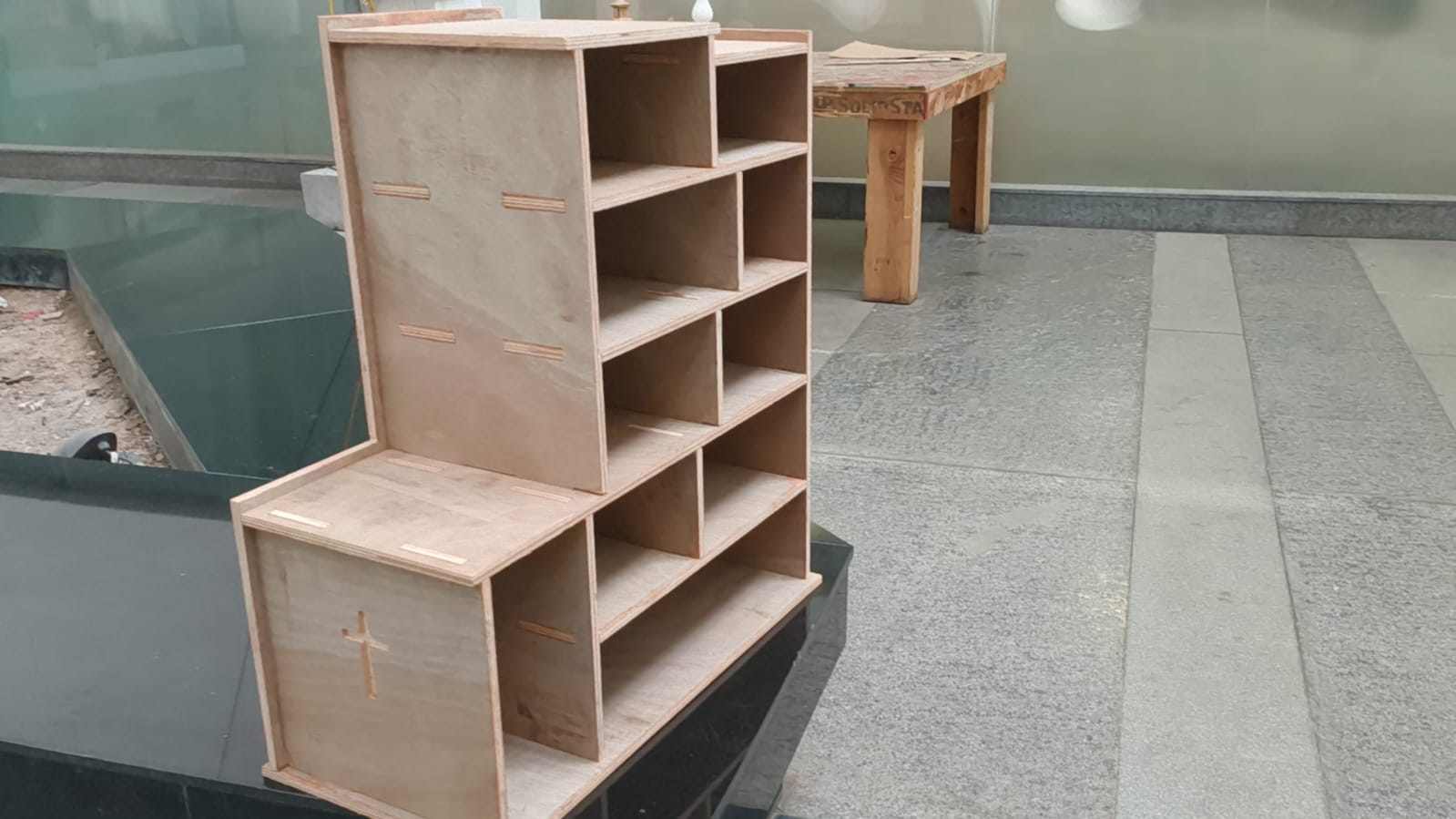
The cross symbol on the top panel was engraved using a separate Profile Toolpath set to a shallower depth, it marks the surface without cutting through.
The pass depths were set to 5.0 mm total across 2 passes at 2.5 mm each (2.5 → 5.0 mm), keeping the cut well within the 12.228 mm sheet thickness.
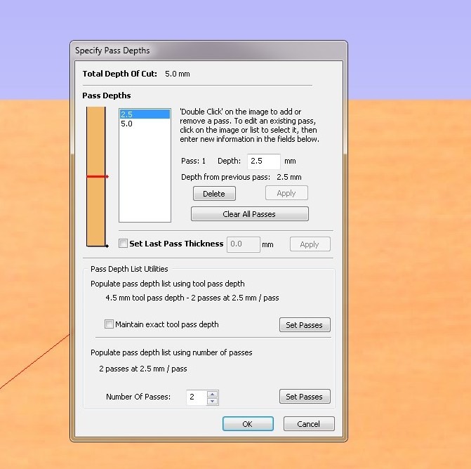
Engraving pass depths, 5.0 mm total, 2 passes at 2.5 mm each. Shallower than the cut-through profile to engrave without separating material.
Within the 2D Profile Toolpath dialog, holding tabs were configured using the Add tabs section at the bottom of the panel.
Tabs are small bridges of uncut material left at intervals along the profile cuts, preventing parts from coming loose and shifting into the spinning bit before the cut finishes. The tab length and thickness were set here before calculating the toolpath.
Add Tabs settings in the Profile Toolpath dialog, tab dimensions configured here before the toolpath is calculated.
Then toolpaths were created for the outlines as well using the same settings.
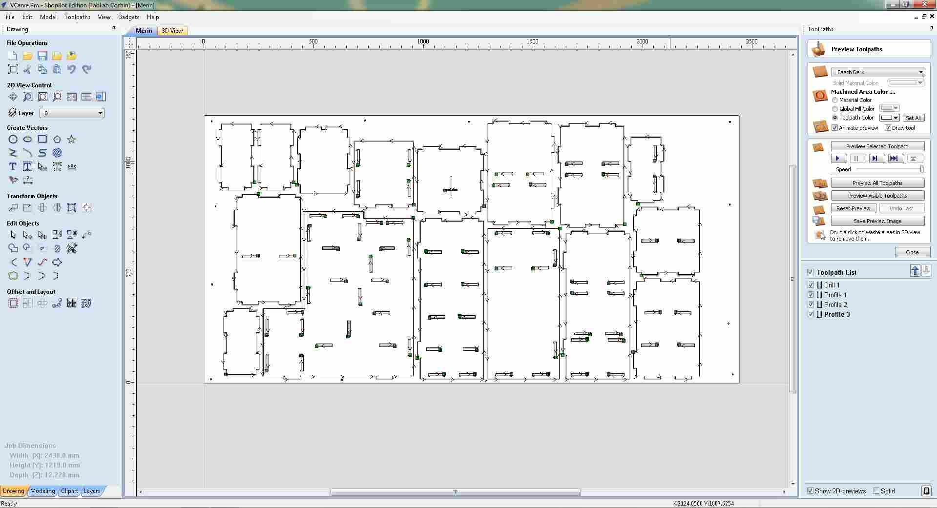
With the profile toolpaths created, Preview All Toolpaths was run to confirm the complete cut plan on the 3D material view. Drill 1 was not included in this preview,only the profile and engraving toolpaths were checked, showing the routing paths across the sheet before exporting.
3D simulation, profile and engraving toolpaths previewed across the sheet. Drill 1 was not selected for this preview.
Complete toolpath setup, all four toolpaths (Drill 1, Profile 1, Profile 2, Profile 3) visible in the Toolpath List before export.
11. Export Toolpath Files
With all four toolpaths created, Drill 1, Profile 1, Profile 2, and Profile 3, the complete layout was reviewed one final time in the 2D view before exporting. Each toolpath is listed in the Toolpath List panel on the right.
Toolpaths were saved as separate .sbp files for the ShopBot. Drill 1 was exported first on its own, with only it checked in the Toolpath List, so it could be run as a dedicated drilling pass before any profile cutting begins.
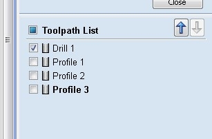
Drill 1 selected in isolation for export, profile toolpaths unchecked so only the drilling pass is saved to this file.
The Save Toolpaths panel confirmed the export settings: Drill 1 with the 6 mm single-flute Fab End Mill, using the ShopBot TC (MM) (*.sbp) post processor. The Save Toolpath(s) to File button was clicked to write the file.
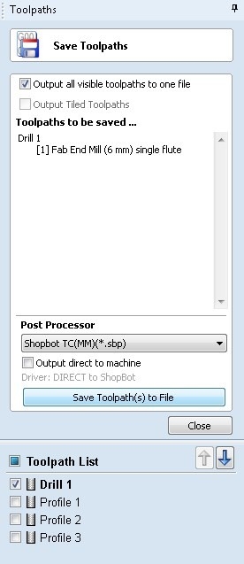
Save Toolpaths panel
The Save Toolpath dialog was opened and the file saved to the local folder in ShopBot's TC (MM) .sbp format, ready to be loaded directly into the ShopBot control software.
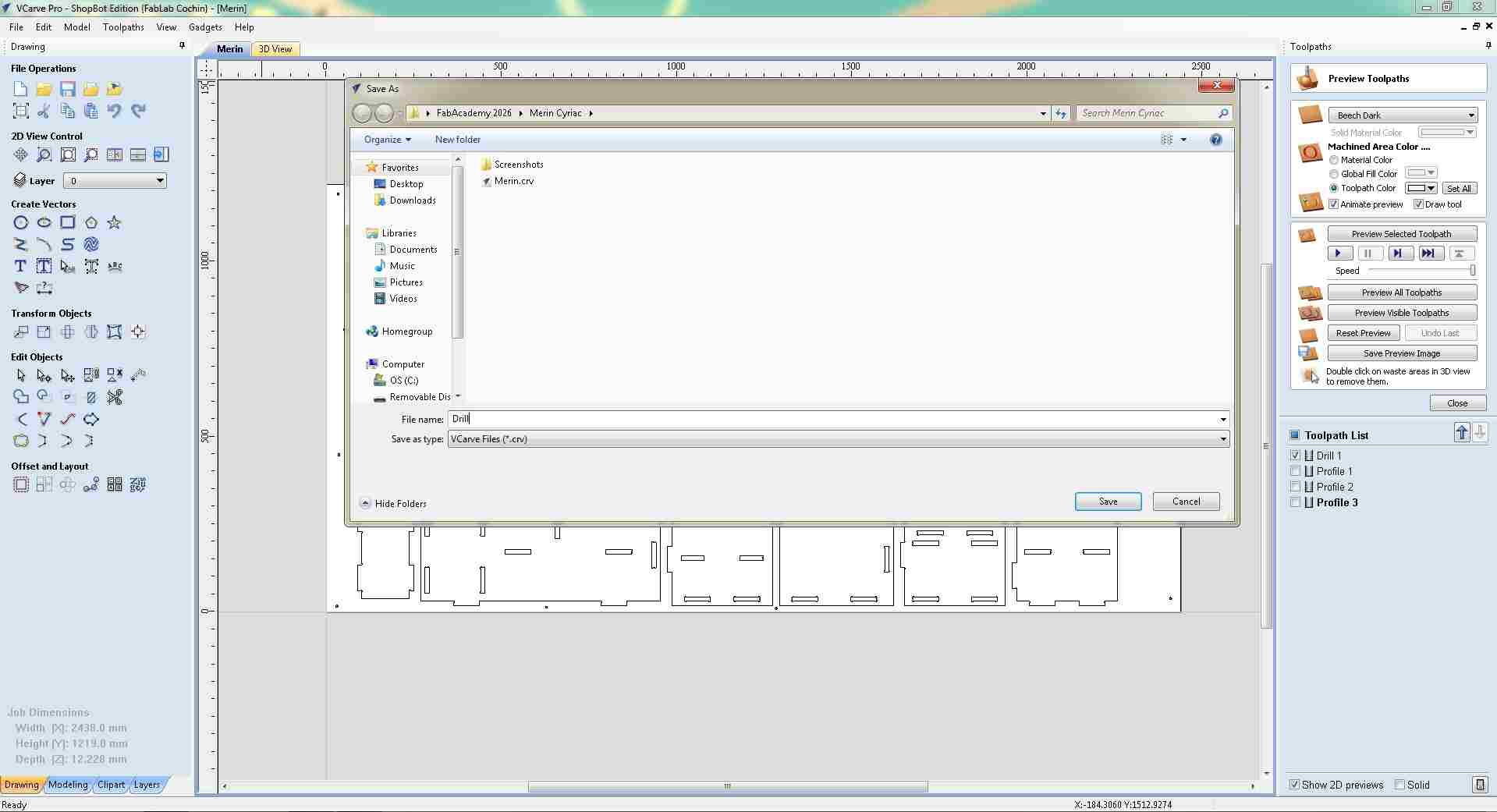
Save dialog, exporting Drill 1 as a .sbp file for the ShopBot.
Next, Profile 1, Profile 2, and Profile 3 were all checked together in the Toolpath List and saved as a second file, grouping all the profile cuts so they run in sequence in one operation after drilling is complete.
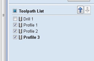
Profile 1, 2, and 3 selected together for export, all profile cuts combined into one .sbp file to run sequentially after drilling.
Step 11: ShopBot Machine Setup and Zeroing
`With the .sbp files ready, the ShopBot control software was opened on the machine computer. The 3D sheet view appears in the background alongside the console terminal. The Position panel (top right) shows the machine coordinates, and the status is set to ACTIVE before jogging begins.
ShopBot control software launched, console terminal open, machine position panel showing coordinates, 3D sheet view visible in background.
The KeyPad jog controller was opened to manually move the spindle to the work origin. The machine status shows ACTIVE, confirming the controller is live and the tool is ready to move.
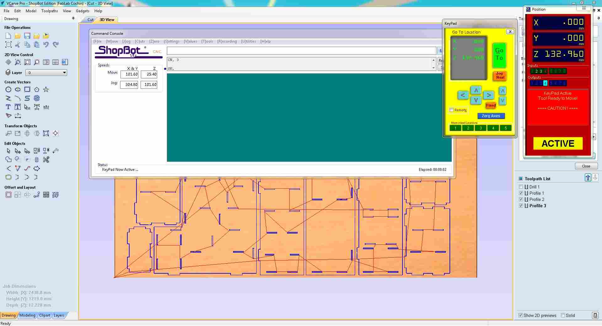
KeyPad open for manual jogging, machine ACTIVE, spindle being moved to the work origin position.
The KeyPad confirms the current spindle position as X: 2.466 mm, Y: 6.783 mm, Z: 1.935 mm. The caution prompt, "KeyPad Active, Tool Ready to Move!", is shown in the Position panel as a reminder that the machine is live and any input will move the spindle.
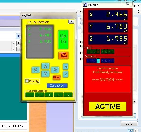
KeyPad active, current spindle position X: 2.466 mm, Y: 6.783 mm, Z: 1.935 mm. Caution prompt confirms the machine is live.
With the spindle positioned at the work origin corner of the sheet, X and Y axes were zeroed using the Zero Axes function. The Select Axes to Zero dialog was opened with X-Axis and Y-Axis both checked, then confirmed to set the current position as the (0, 0) reference for all toolpaths.
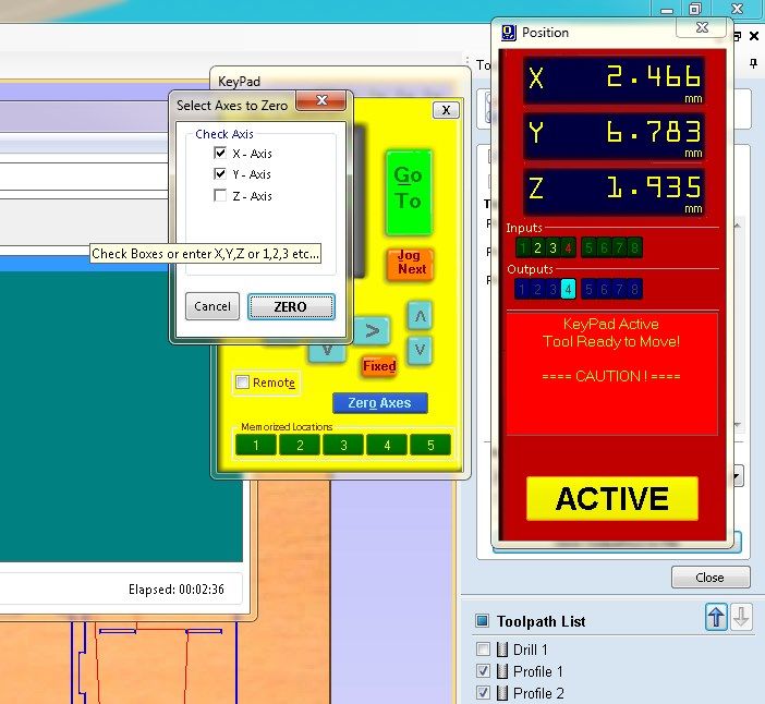
Zeroing X and Y axes, both axes selected in the dialog; clicking Zero sets the current spindle position as the (0, 0) work origin.
The console confirmed the X and Y zeroing with the message: "Tool is now Zeroed in X and Y Axis (At 0001)". OK was clicked to dismiss and proceed to Z-axis zeroing.
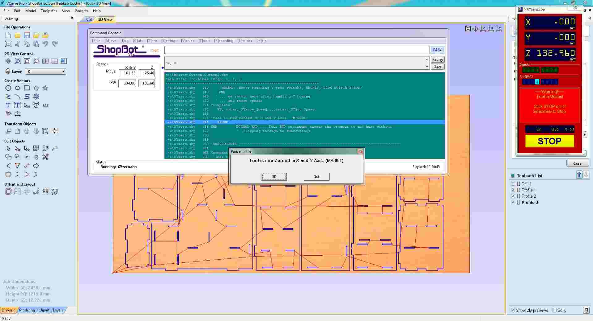
X and Y zeroed, confirmation dialog reads "Tool is now Zeroed in X and Y Axis". OK clicked to proceed to Z zeroing.
For Z-axis zeroing, the touch-plate method was used. The console prompted: "HIT ENTER! When above plate and Ready to Zero (At 0010)", indicating that the alligator clip had been attached to the bit and the touch plate placed on the material surface, ready for the automatic Z-probe routine.

Z-zeroing prompt, operator confirms the touch plate is in position and the spindle is above it before the auto-probe routine lowers the bit to find the material surface.
After the Z-probe completed, the console displayed a safety reminder: "PLEASE REMEMBER TO REMOVE ALLIGATOR CLIP AND PUT AWAY PLATE". This is a critical step, leaving the clip attached during cutting would create a short-circuit risk as the bit moves across the sheet.
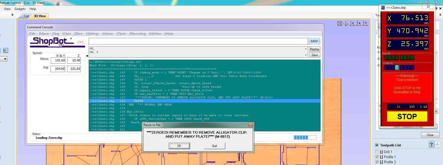
Post-Z-zero safety reminder, alligator clip and touch plate must be removed before cutting starts to avoid a short-circuit.
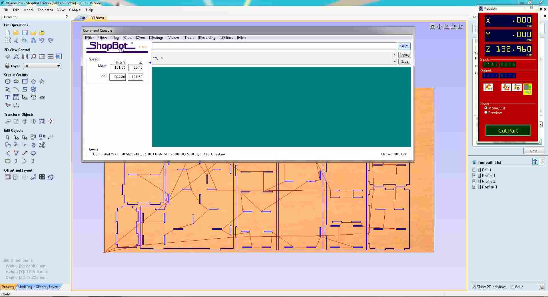
With X, Y, and Z all zeroed, the Position panel and Toolpath List confirmed the machine was ready to cut. Profile 1, Profile 2, and Profile 3 were all checked in the Toolpath List, and the Cut Part button was visible and ready to initiate the run.
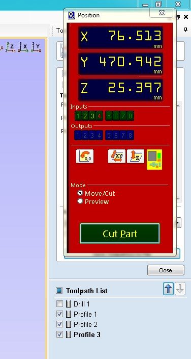
Machine zeroed and ready, Profile 1, 2, and 3 checked in the Toolpath List; Cut Part button confirms the ShopBot is ready to run.
13. Running the Toolpaths on the ShopBot
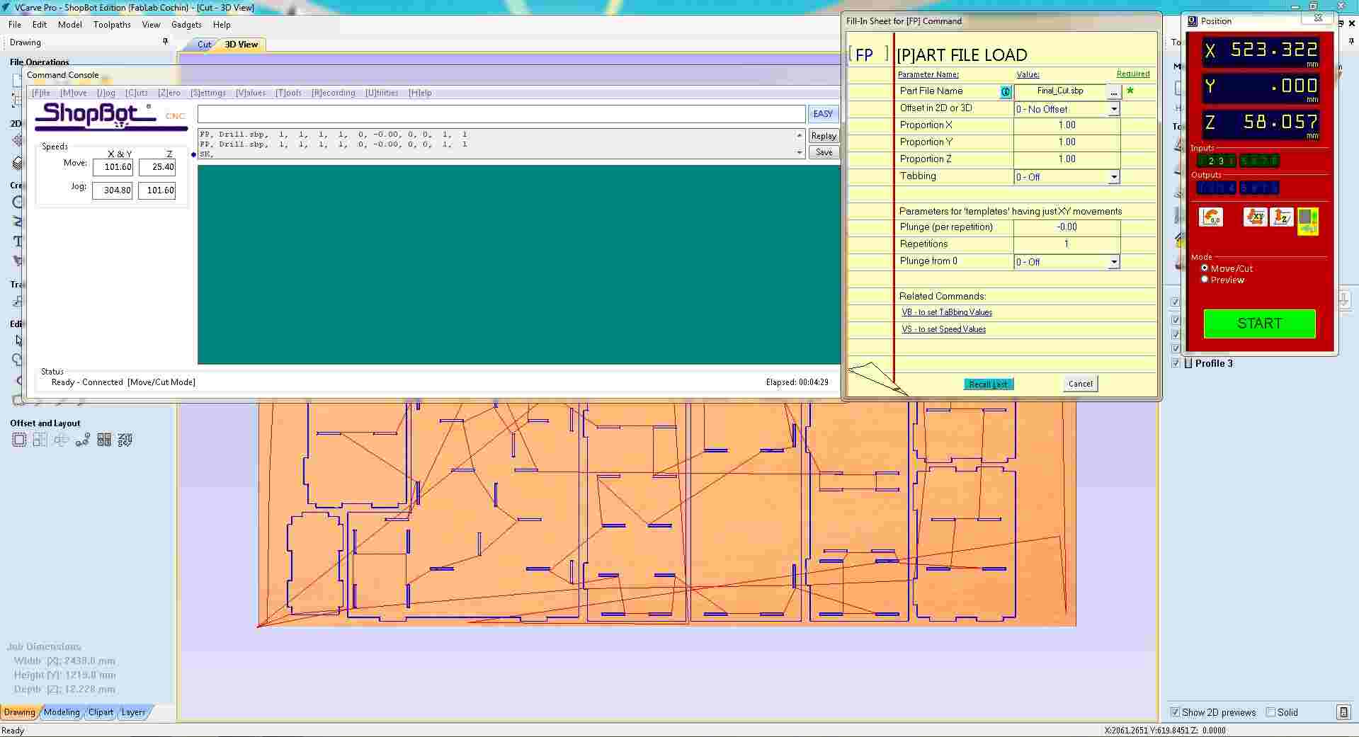
The first .sbp part file was loaded into the ShopBot using the FP, Part File Load command. The dialog shows the file path and cutting parameters before the run begins. The Position panel displays the current machine coordinates as the operator confirms the file is correct.
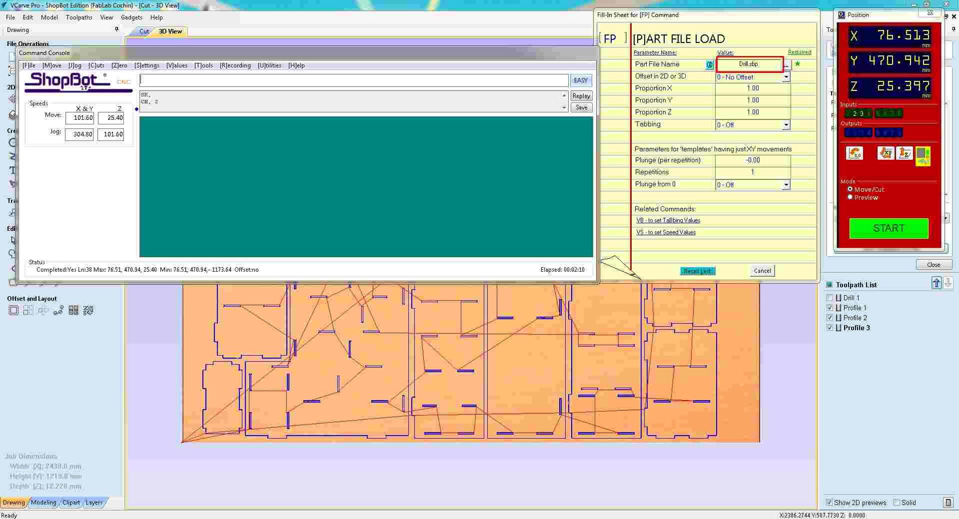
Part file loaded via FP command, file parameters confirmed before the toolpath run begins.
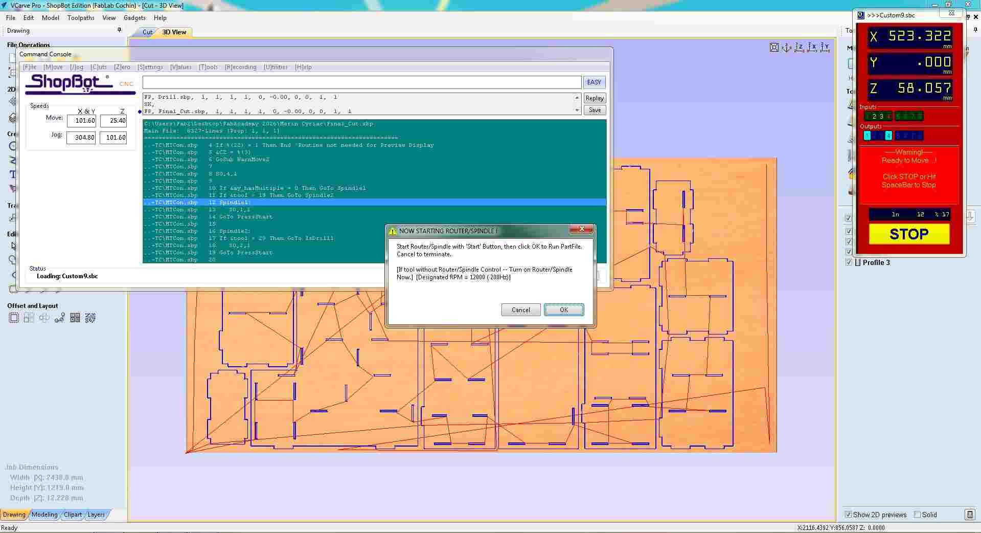
The ShopBot console prompted: "Start Routine with 'Start' Button then click 'Ok' to Run PartFile". This step also requires the operator to turn on the router/spindle manually before clicking OK, ensuring the bit is spinning before it enters the material.
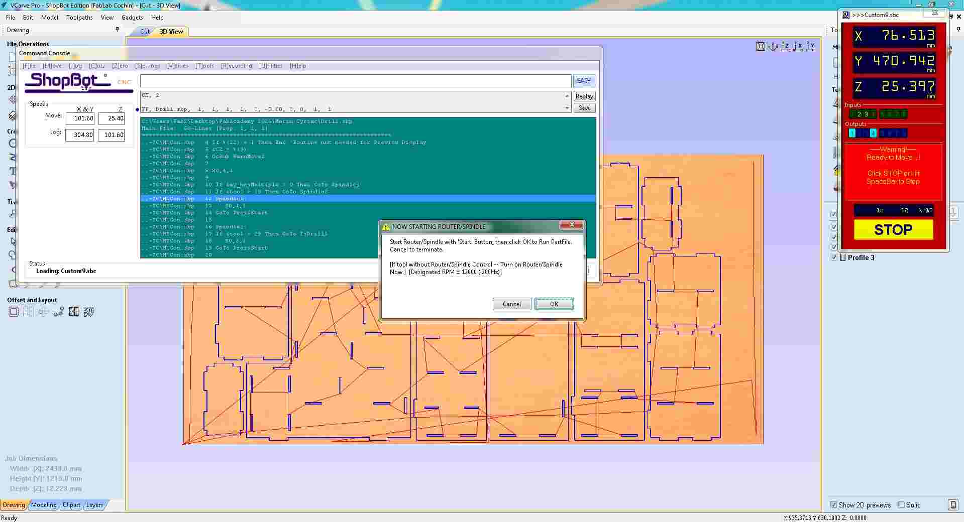
Pre-cut confirmation, operator starts the spindle, then clicks OK to begin the toolpath run. The machine holds until confirmed.
the machine drilled all the holes according to Drill 1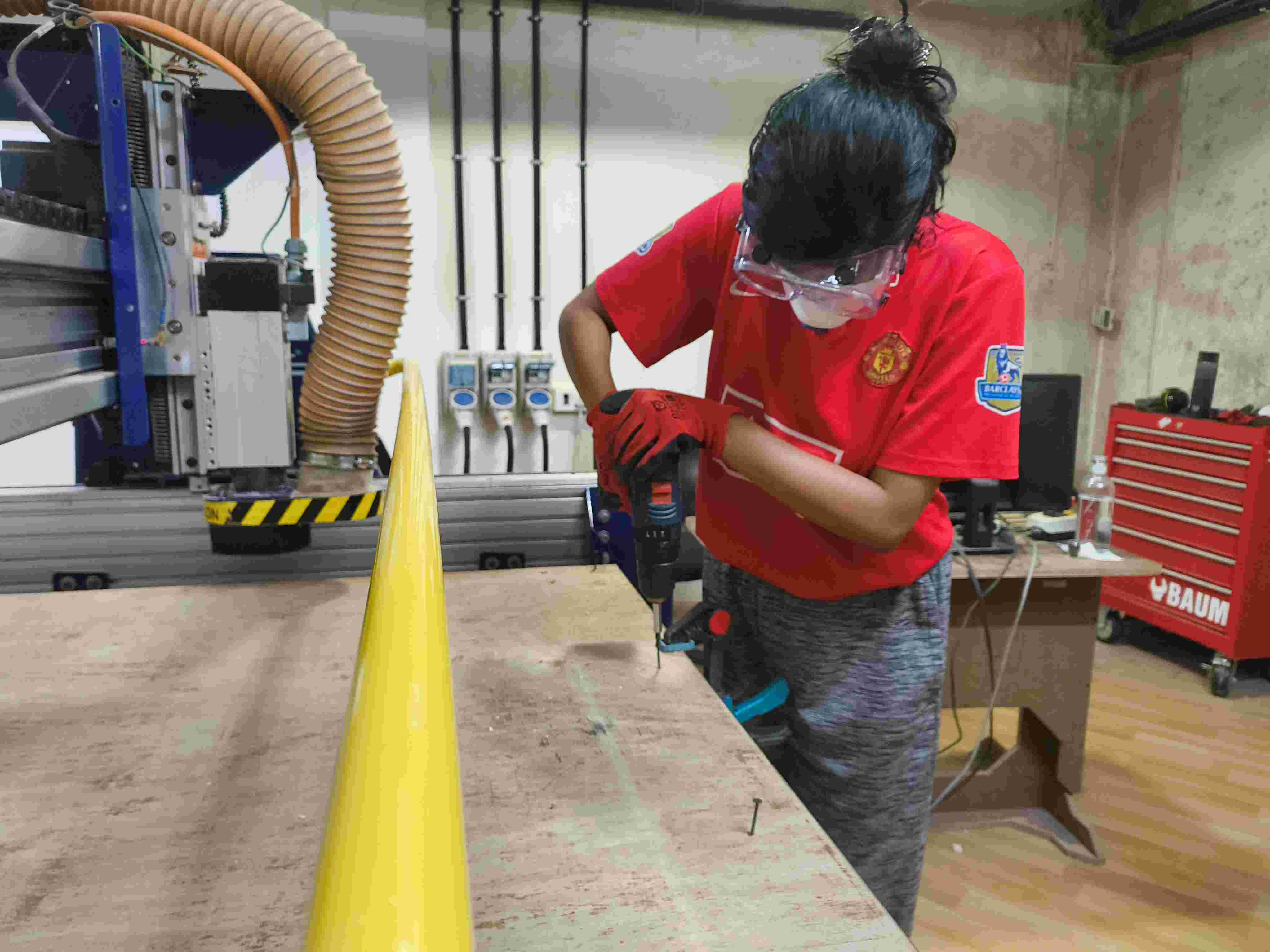
The second .sbp file was loaded for the next toolpath pass using the same FP command. The Position panel shows the machine has moved to a new coordinate after completing the previous pass, and the status returned to ACTIVE ready for the next file.
Second toolpath file loaded, machine returned to ACTIVE after the previous pass; next .sbp file queued and ready to run.
The same start-routine confirmation dialog appeared again for the second file, requiring the spindle to be started and OK clicked before the ShopBot would proceed. This two-step confirmation is repeated for each part file loaded, ensuring the operator is present and attentive at the start of every pass.
Start-routine confirmation repeated for the second pass, spindle started, OK clicked to begin the next toolpath run.
This was repeated for each of the remaining toolpath files, with the ShopBot cutting all the parts from the sheet according to the VCarve toolpaths.
Post-Processing
After the ShopBot finished cutting, the parts could not simply be lifted off the sheet. Several steps were needed to bring the cut pieces to a clean, assembly-ready state.
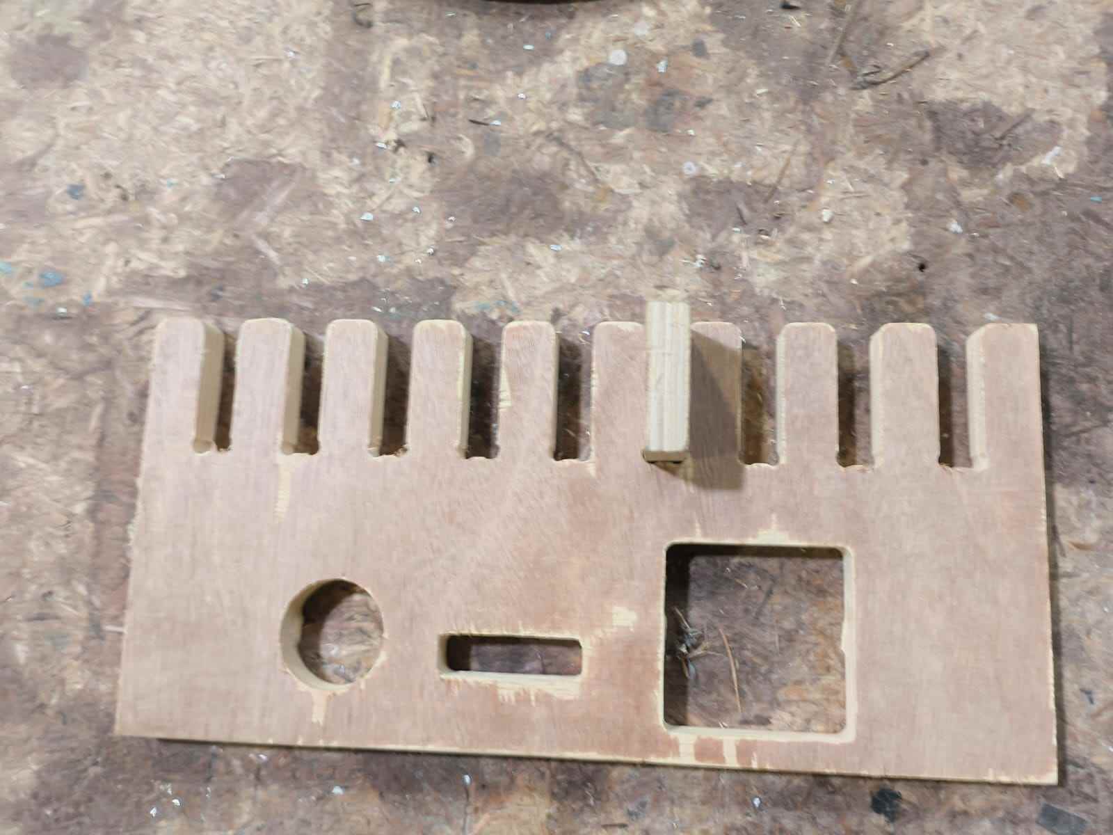
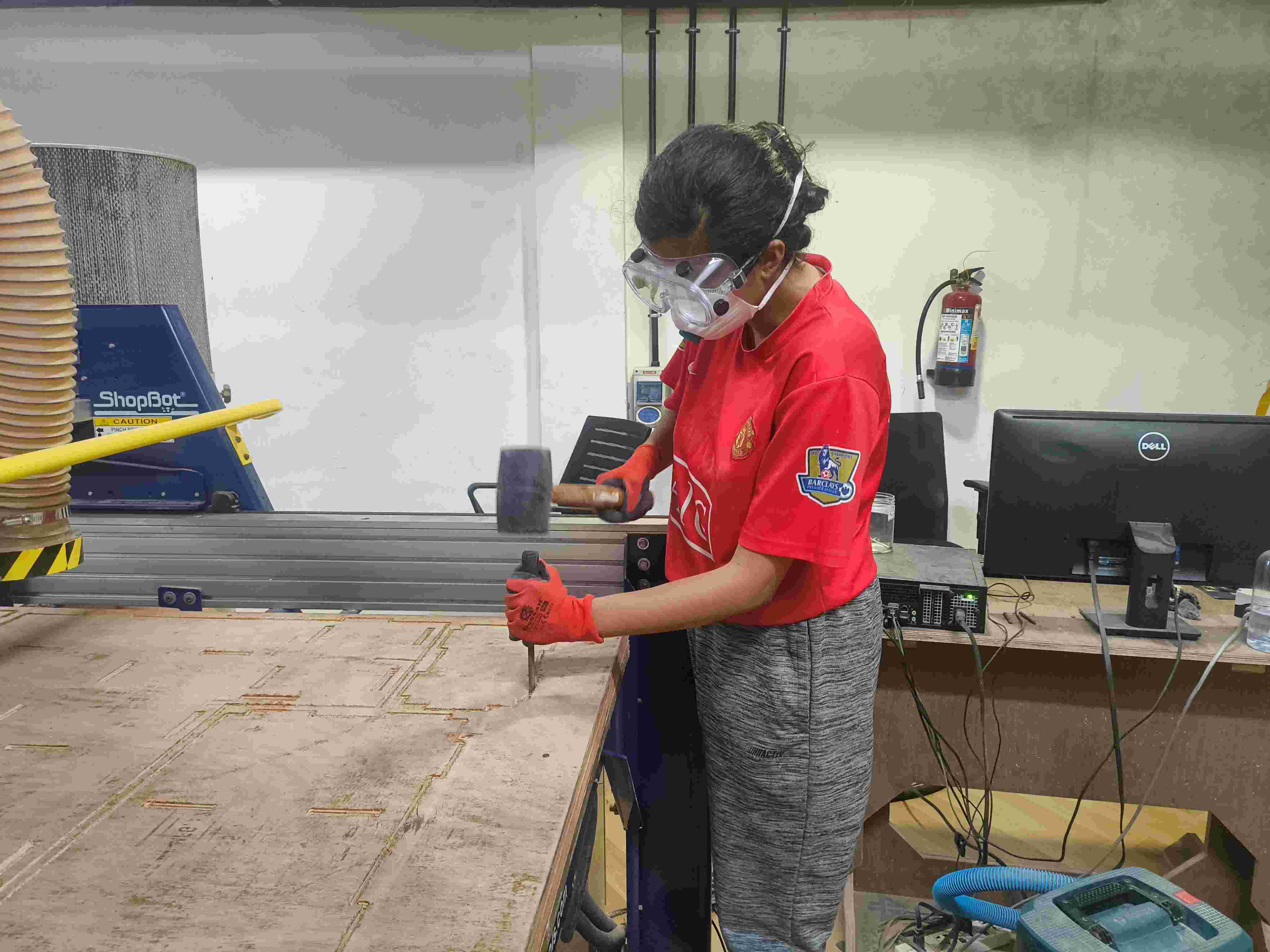
1. Remove Parts from the Sheet
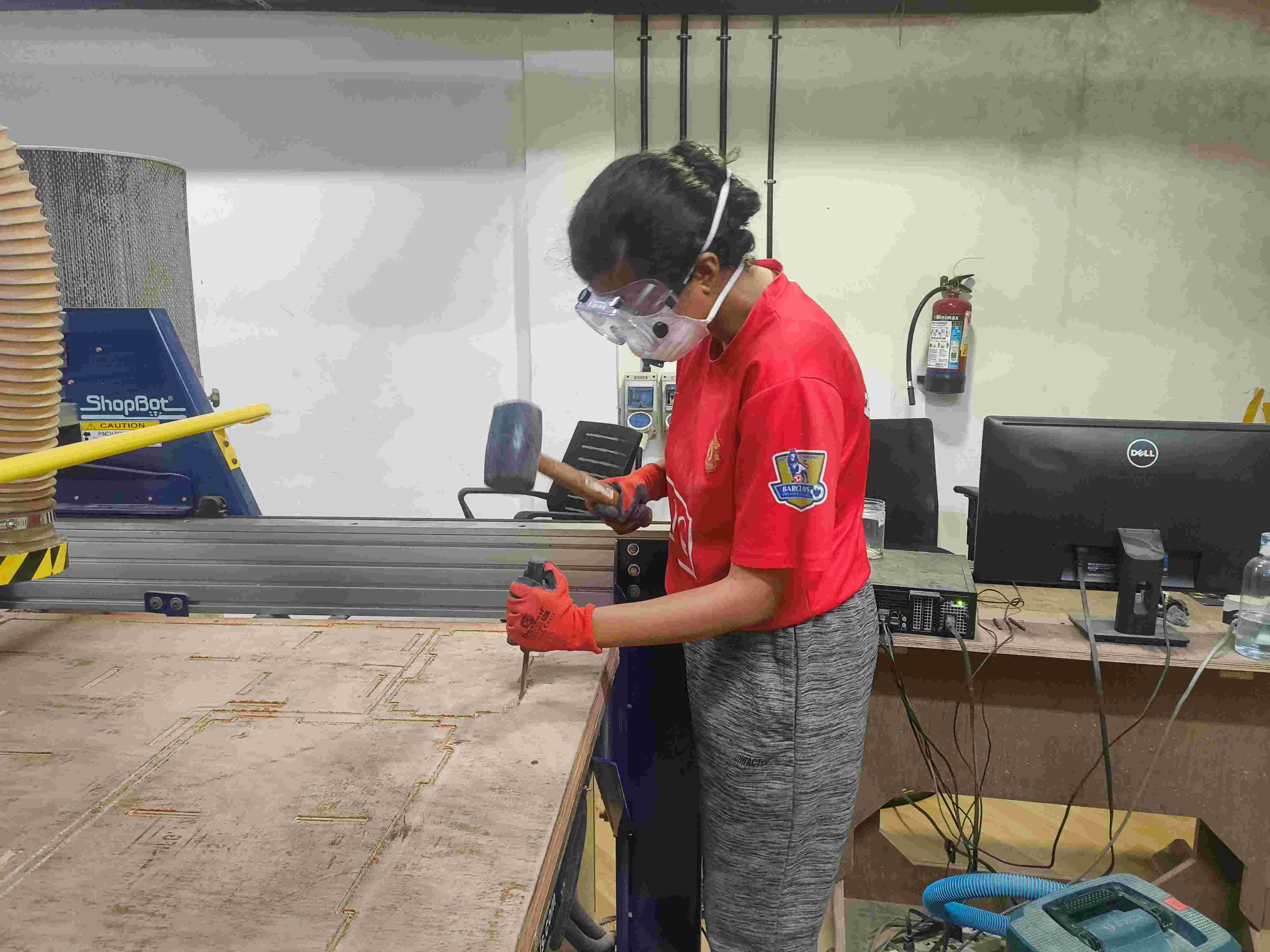
Each panel was held to the surrounding sheet by the holding tabs configured in VCarve. A chisel and mallet were used to snap each tab cleanly, working along the part edge rather than against it to avoid splitting the grain. Once all tabs were broken, the panels were lifted free.
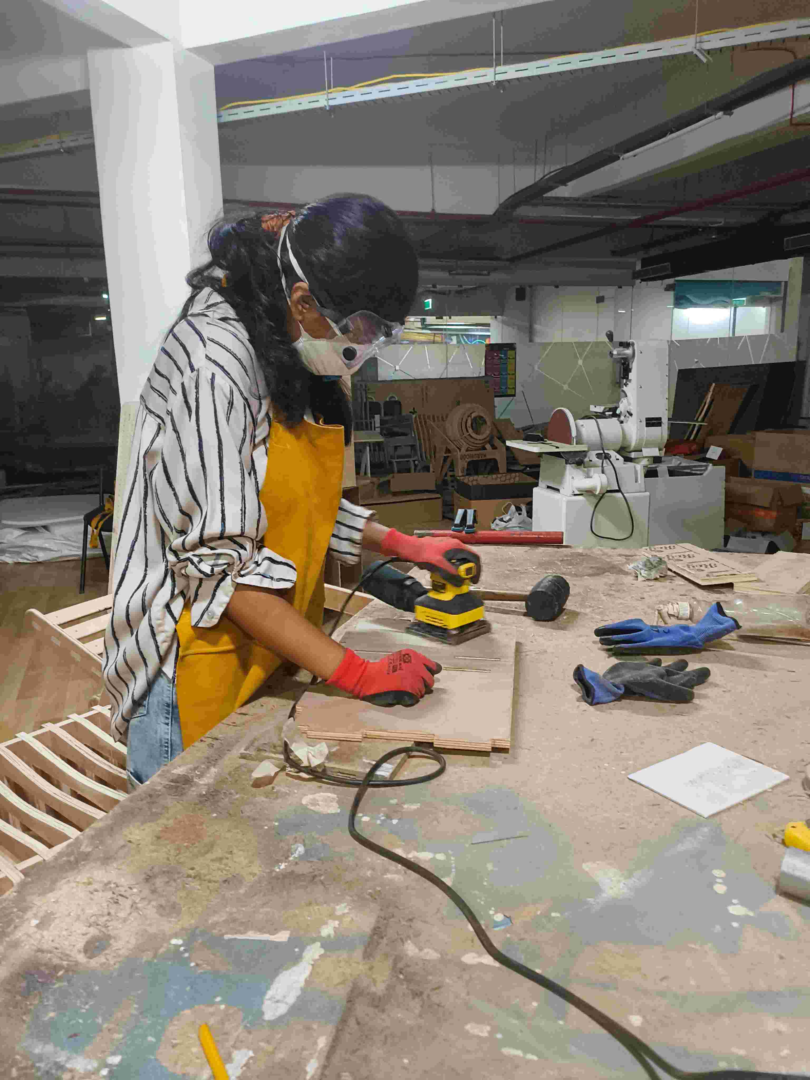
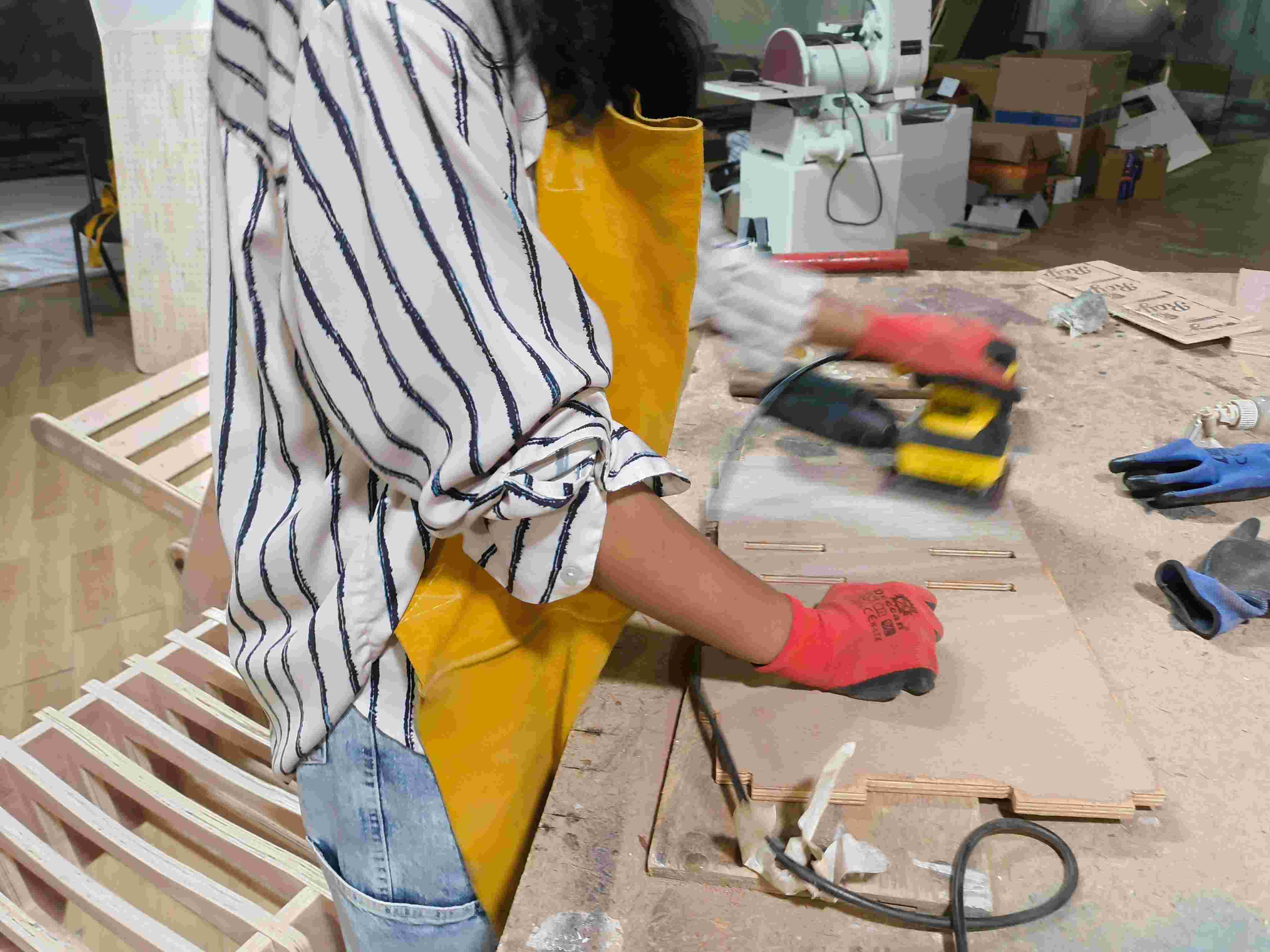
2. Clean Up Tab Witness Marks
Where each tab broke, a small raised nub of material remained on the part edge. These were removed with a sharp chisel, paring flush with the surrounding surface, and then smoothed with 80-grit sandpaper wrapped around a block.
3. Sand All Edges
The CNC-cut edges were smooth but sometimes showed slight fuzz from the end mill passing through the wood fibres. All edges were sanded progressively with 80-grit then 120-grit sandpaper, moving with the grain. The joint slot openings were left unsanded to preserve the tight press-fit tolerance; sanding inside a slot would widen it and reduce the joint strength.
4. Dry-Fit the Joints
Before final assembly, every joint was test-fitted by hand. A correct press-fit joint requires deliberate hand pressure to seat — it should not slide in freely (too loose) nor require a mallet to close (too tight, risk of splitting). Any joints that were slightly too tight had their mating edges lightly dressed with sandpaper until they seated with firm hand pressure.
5. Final Assembly
With all joints verified, the doll house was assembled by pressing each panel into its corresponding slots in order, starting with the floor, then the side walls, then the front and back panels, and finally the roof. No glue or fasteners were used; the press-fit joints hold the structure together by friction and geometry.