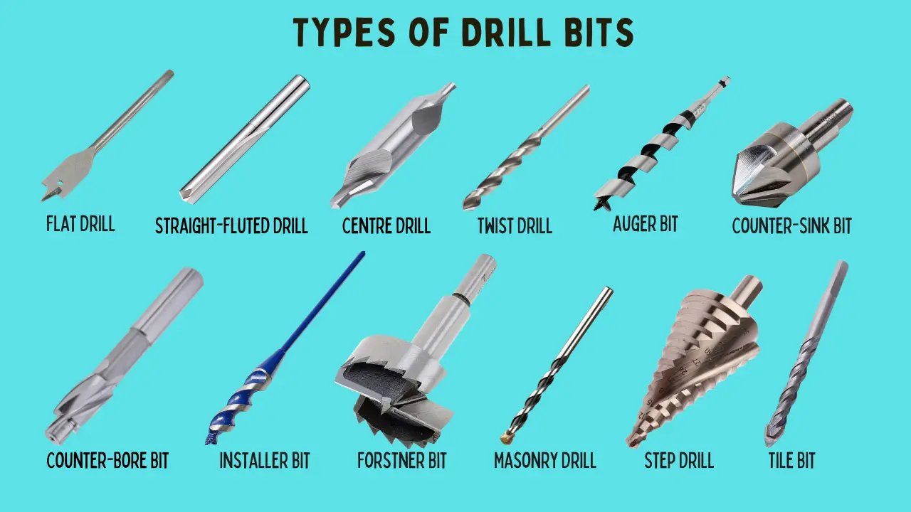
Tools
"Bit"
A router cutting tool is generally called a bit. The word bit in this context derives from the Old English word bite meaning to bite or cut into something. It has been used in tool-making for centuries to describe any small cutting implement that is held and driven by a larger tool.
A drill bit “bites” into wood. A router bit “bites” into the surface. The bit is never the machine — it is the cutting element the machine drives.
The router is the machine. The bit is the cutting tool the router holds and spins. Together, the bit mounted in the router is referred to as a router tool in formal engineering and manufacturing contexts.
The purpose of any CNC router bit is to remove material from a workpiece in a controlled, repeatable, and precise manner. To fulfil this function, the cutting tool must satisfy four fundamental engineering requirements:
- It must be composed of a material harder than the workpiece.
- Its cutting geometry must be sufficiently sharp to shear fibres rather than displace them.
- It must rotate at a velocity adequate to produce a clean, consistent cut.
- Its geometry must permit continuous chip evacuation to prevent recutting and heat accumulation.
Every aspect of a router bit's design its profile, material, flute count, helix angle, and shank dimensions exists to satisfy one or more of these requirements. Understanding the rationale behind each design decision is prerequisite to using the tool effectively.
Structural and Material Requirements of a Routing Tool
A routing tool must satisfy four fundamental requirements to function correctly within a CNC spindle. Each requirement directly determines a specific aspect of the tool's geometry, composition, and surface finish.
The Shank
The shank is the smooth, precision-ground cylindrical section of the routing tool that seats within the spindle collet. The collet exerts radial clamping force uniformly across the shank surface, transmitting rotational torque from the spindle to the tool body.
The shank must be manufactured to tight dimensional tolerances. Any deviation in concentricity or surface finish introduces radial runout — a condition in which the tool's cutting axis deviates from its rotational axis during operation. At spindle speeds of 10,000 to 24,000 RPM, even marginal runout produces measurable vibration, dimensional inaccuracy in the cut, accelerated flute wear, and risk of catastrophic tool failure.
The Cutting Edge
The cutting edges of a routing tool are formed along the leading face of each flute. Their function is to shear workpiece fibres along a defined plane rather than displace or compress them.
The distinction is mechanically significant. A sharp cutting edge initiates a clean fracture along the fibre grain, requiring relatively low cutting force and generating minimal heat. A worn or insufficiently sharp edge cannot initiate a clean shear — it compresses fibres ahead of it, increasing cutting resistance, elevating temperature at the tool-workpiece interface, and producing a torn rather than sliced surface.
The Flute Channels
Material removal generates chips and particulate debris continuously throughout the cutting operation. If this material is not evacuated from the cutting zone, it accumulates within the tool path, where it is recut by subsequent flute passes. Recutting does not remove material efficiently — it generates frictional heat, increases spindle load, and degrades surface finish.
The open helical channels between the flutes serve as the chip evacuation pathway. As the tool rotates, the helix geometry directs chips along the channel and away from the active cutting zone, ensuring that each flute pass engages clean, unobstructed workpiece material.
Material Composition
The operating environment of a routing tool imposes severe demands on its substrate material. Rotational speeds in excess of 10,000 RPM, combined with continuous frictional contact with the workpiece, generate sustained thermal and mechanical loading at the cutting edge.
Standard steel alloys lack the hardness and thermal resistance necessary to maintain cutting geometry under these conditions. Routing tools are therefore manufactured from tungsten carbide — a composite material of tungsten carbide particles bonded in a cobalt matrix — which provides a hardness significantly greater than steel and retains its cutting geometry at elevated temperatures. This thermal and mechanical stability is the primary reason carbide has become the industry standard substrate for precision routing tools.
Why the Bit Is Spiral / Twisted
The spiral geometry is the most important design decision on any routing bit, and it is worth understanding in detail.
What Happens Without a Spiral
Imagine straight vertical teeth with no twist at all. Every cutting edge hits the wood at exactly the same moment with every rotation. This causes:
- A sudden impact load with every rotation.
- Massive vibration throughout the cut.
- A rough, torn surface finish.
- Enormous mechanical stress on the bit itself.
What the Spiral Does
The spiral means the cutting edge enters the wood gradually — one point at a time, in a smooth continuous slice, like a zipper closing. This produces:
- Smooth, continuous cutting force with no sudden impacts.
- Minimal vibration.
- A clean, precise cut.
- Much less mechanical stress on the bit.
Think of it this way: which is more controlled — slamming a door or closing it smoothly? The spiral does for cutting what a hinge does for a door. It converts a sudden impact into a smooth, controlled action.
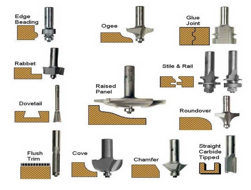
- Straight / Upcut Spiral Bits — Used for general cutting, dadoes, and grooves. The upcut helix pulls chips upward, keeping the cut clean at the bottom.
- Downcut Spiral Bits — Pushes chips downward, producing a clean top surface. Ideal for laminates and veneered materials.
- Compression Bits — Combines upcut and downcut spirals, producing clean edges on both top and bottom simultaneously. Popular for cutting plywood and melamine.
- V-Bits — V-shaped profile used for engraving, lettering, decorative carving, and chamfering edges. Common angles: 30°, 45°, 60°, 90°.
- Ball Nose Bits — Rounded tip used for 3D carving, contoured surfaces, and relief work. Available in various radii.
- Surfacing / Spoilboard Bits — Large-diameter flat bits used to skim and flatten spoilboards or large flat surfaces.
- Tapered Ball Nose Bits — Used for fine 3D detail work, combining a taper with a ball tip for better reach and rigidity.
- Mortising / Dado Bits — Flat-bottomed bits for cutting precise slots, dadoes, and rabbets.
- Drill Bits — Used for boring holes. Types include brad point, spiral, or spot-drilling, depending on the material.
Tool Materials
- High-Speed Steel (HSS) — Economical option, suitable for soft materials.
- Solid Carbide — Durable and handles harder materials and higher speeds.
- Carbide-Tipped — Carbide cutting edges on a steel body; a cost-effective middle ground.
Key Tool Parameters
| Parameter | What It Affects |
|---|---|
| Flute count | Chip clearance and finish quality |
| Helix angle | Cutting action and heat dissipation |
| Diameter | Cut width and spindle load |
| Shank size | Collet compatibility (¼", ½" common) |
| Coating (TiN, TiAlN) | Heat resistance and tool life |
Common Materials and Recommended Tools
| Material | Recommended Tool |
|---|---|
| Softwood / Hardwood | Upcut or compression spiral bit |
| MDF / Plywood | Compression or downcut spiral bit |
| Aluminum | Single-flute carbide, O-flute bit |
| Plastics / Acrylic | Single-flute, O-flute (prevents melting) |
| Foam | Ball nose or straight bit |
| Stone / Composites | Diamond-coated bits |
Flutes
V Bits in CNC Milling
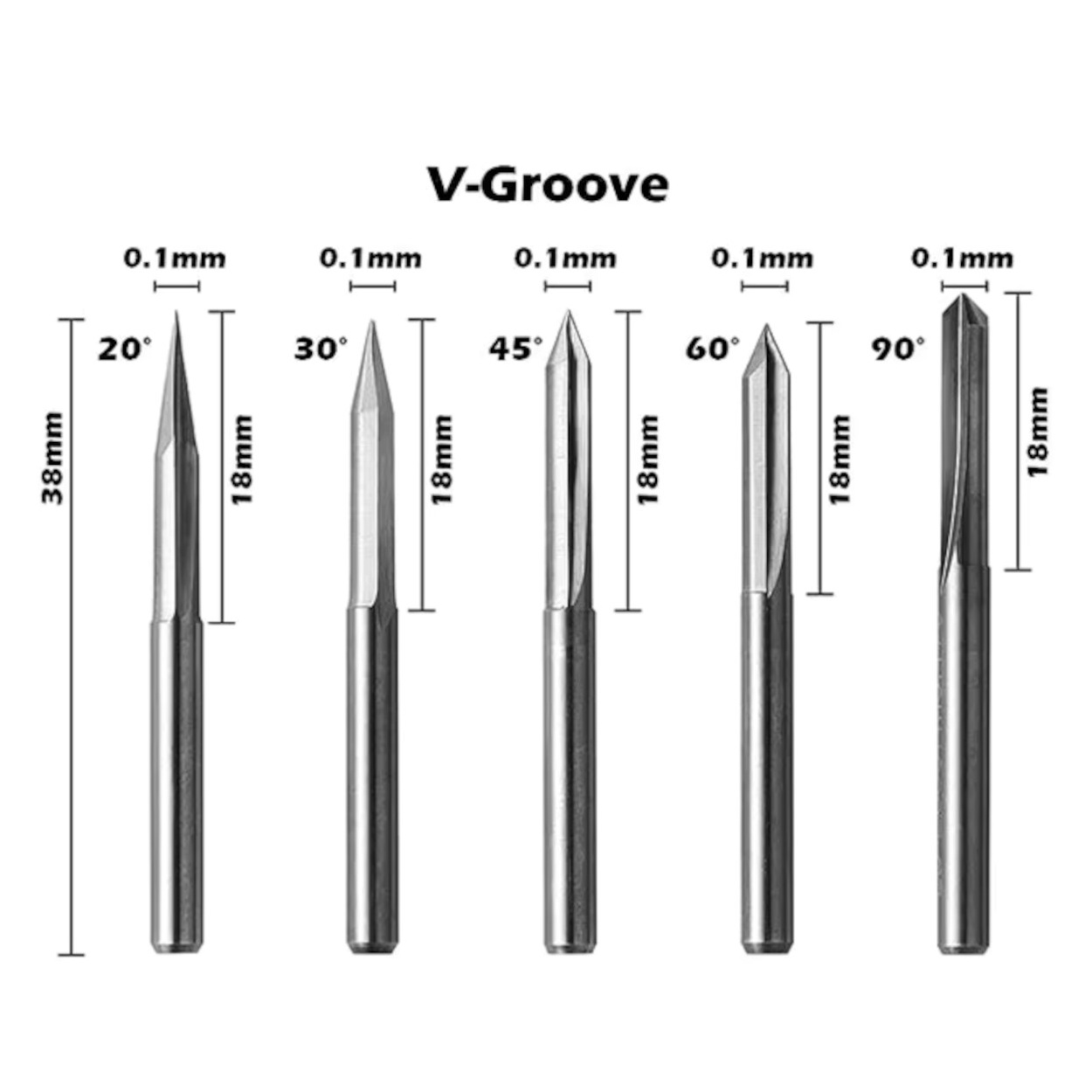
A V bit (also called a V-groove bit) is a type of CNC cutting tool with a pointed, angled tip shaped like the letter "V". Unlike flat end mills that cut with a flat bottom, V bits taper to a sharp point, which makes them ideal for engraving, chamfering, and creating sharp interior corners and decorative details.
How V Bits Work
The V-shaped geometry of the bit means the cutting width changes depending on the depth of cut. When the bit cuts deeper into the material, the groove becomes wider. This property is used in V-carving, where the software varies the depth to create variable-width cuts that follow the outlines of text or artwork, resulting in a clean, professional engraved appearance.
Common V Bit Angles
- 30° — Very sharp, used for fine detail engraving and small text.
- 45° — Good balance between detail and cutting speed; common for chamfering edges.
- 60° — Popular for general V-carving and decorative engraving.
- 90° — Used for wider chamfers and larger lettering.
Applications of V Bits
- Engraving: Carving text, logos, and decorative patterns into wood or other materials.
- Chamfering: Cutting a beveled edge along the corner of a part.
- V-Carving: Creating variable-depth cuts that produce artistic, relief-style engravings.
- Sign Making: Producing professional-looking signage with sharp, clean letter profiles.
Advantages of V Bits
- Can produce very fine, sharp detail that flat end mills cannot achieve.
- Ideal for engraving and decorative work.
- The pointed tip allows precise cutting in tight corners.
Limitations
- Not suitable for cutting out parts or making flat-bottomed pockets.
- Depth must be carefully controlled to maintain consistent cut width.
- The sharp tip can wear out faster when cutting hard materials.