MOULDING & CASTING
Group Assignment
- Review the safety data sheets for each of the moulding and casting materials
- Make and compare test casts with each of them
- Compare mould making processes
Individual Assignment
- Design a mould around the process you'll be using, produce it with a smooth surface finish that does not show the production process toolpath, and use it to cast parts
- Extra credit: Use more than two mould parts
- Extra credit: Make your own materials
You can view the Group Assignment here.
What is Moulding and Casting?
Moulding and casting is a manufacturing process for reproducing the same shape multiple times. The core idea is simple, you make a mould once, then use it to produce as many copies of a part as you need. It is one of the oldest fabrication techniques humans have used, from bronze-age metal casting to modern industrial injection moulding.
The process has two distinct stages:
Moulding is the process of creating the mould itself which is the the negative cavity that defines the shape of the final part. In Fab Academy, we machine a positive form into wax using a CNC mill, then pour a flexible silicone rubber over it. Once the silicone cures, it peels away as a reusable mould that holds the exact shape of what we machined.
Casting is the process of filling that mould with a material that will harden into the final part. The casting material can be almost anything that starts as a liquid and solidifies — resins, plaster, concrete, metals, chocolate. We typically use urethane resin or hydrostone in the lab because they are safe to handle, cure at room temperature, and produce rigid, durable parts.
The reason this process is so useful is the decoupling it creates. The hard work happens once, at the moulding stage, getting the geometry right, machining it cleanly, producing a good silicone. After that, casting more parts is fast and repeatable. The silicone mould can typically be used dozens of times before it degrades.
In Fab Academy, we go through the full chain: design a part in CAD → machine the positive in wax → cast silicone to make the mould → cast the final material → demould the finished part. Each step depends on the one before it, so understanding the whole process before starting the design is important.
Design
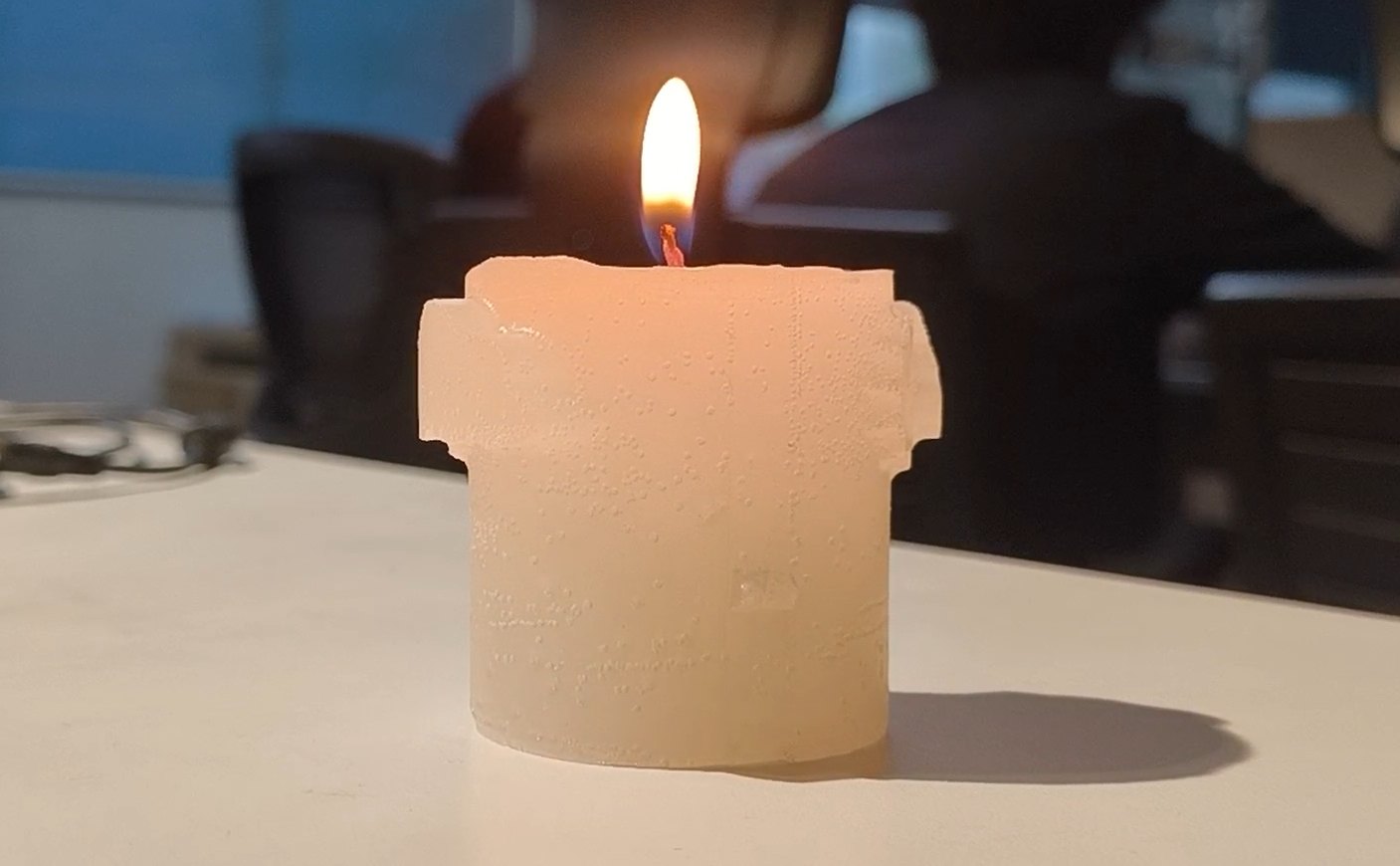
For my individual assignment, I decided to design a decorative candle mould.
A cylinder is a clean, simple form that translates well to casting, but I wanted it to have some character, so I added embossed surface decorations using SVG artwork before working out the mould strategy.
Adding the Decorations
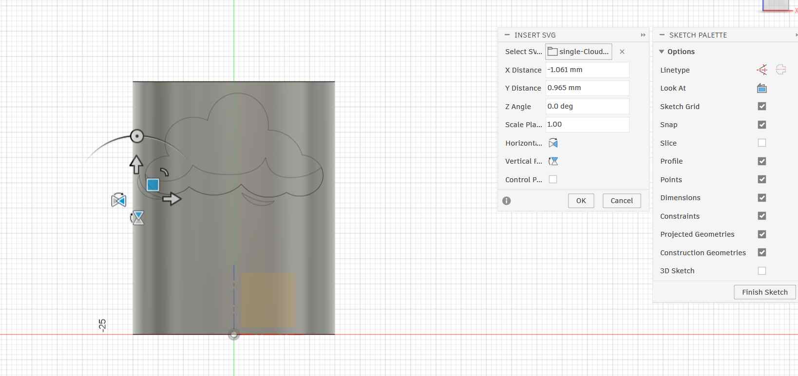
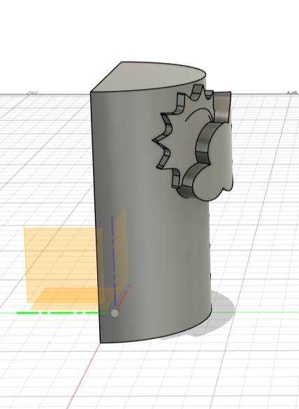
I started with a cylinder body in Fusion 360 representing the candle.
To add the decorative elements, I used the Insert SVG workflow. Fusion lets you place an SVG file directly onto a face or curved surface as a sketch, which you can then use as a profile for embossing.
Embossing the Decoration
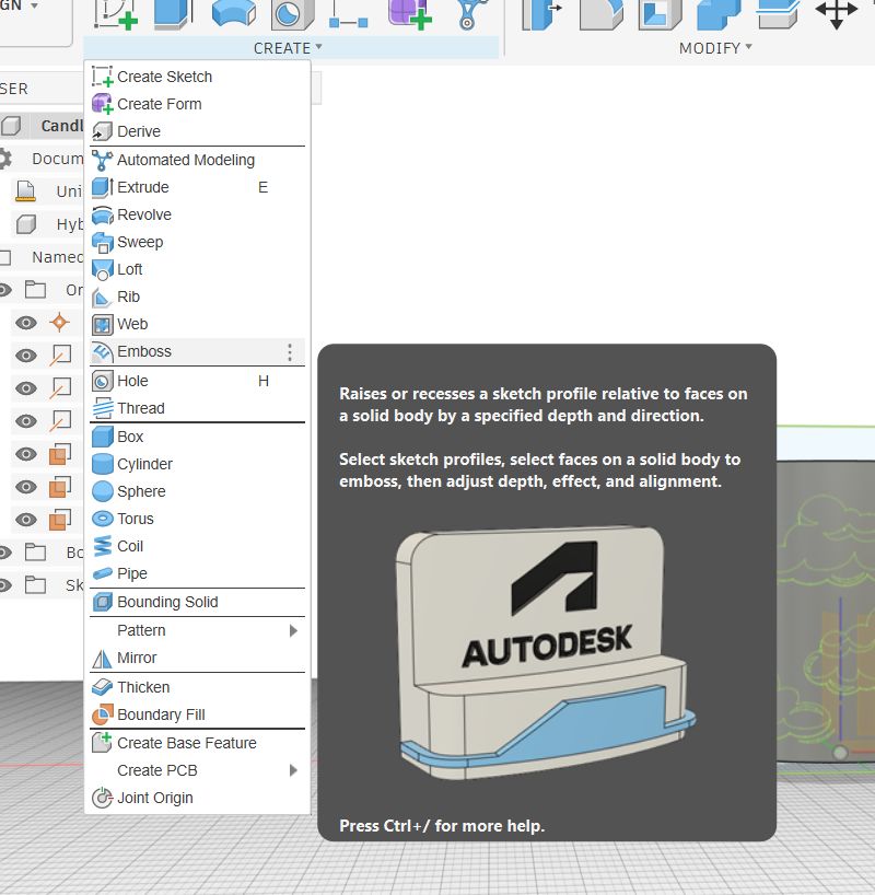
With the SVG sketch on the surface, I used Fusion 360's Emboss tool (Create → Emboss) to raise the cloud profile off the cylinder surface.
The Emboss tool takes a sketch profile and either raises or recesses it relative to the face of a solid body by a specified depth. It handles the geometry of wrapping onto curved surfaces automatically, which would be very difficult to do manually.
Splitting the Body
A solid cylinder cannot be demoulded from a single-piece mould, the curved walls would trap the cast part. To solve this, I used Split Body to cut the cylinder in half along its central axis.
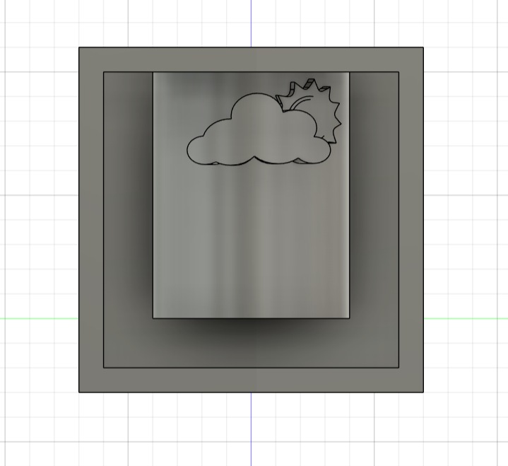
After splitting, I had one half of the candle with the embossed cloud and sun decorations on the curved side, and a clean flat face where the cut was made. This half became the positive for my mould.
Creating the Mould Box
The final step in the design was encasing the candle half inside a rectangular box. This becomes the mould housing that will be machined into wax.
CAM Setup
With the mould design finished, the next step was generating the toolpaths that would drive the CNC machine. Fusion 360 handles both design and CAM in the same file, you just switch workspaces.
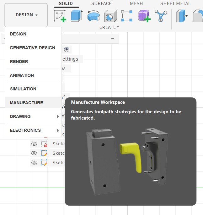
Switching to the Manufacture Workspace
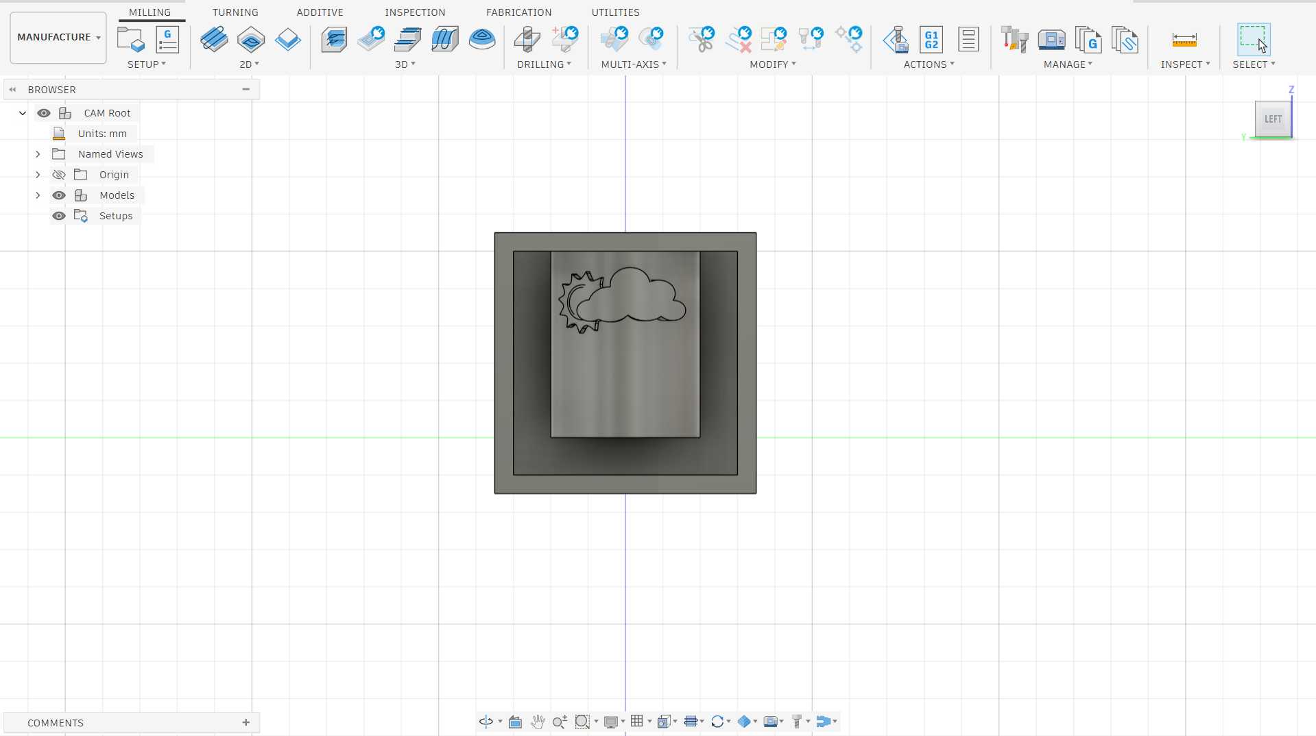
I switched from the Design workspace to the Manufacture workspace using the workspace dropdown at the top left. The Manufacture workspace is where Fusion generates toolpath strategies.
It reads the same 3D body from the design but now interprets it as a stock to be machined rather than a shape to be built.
Importing the Lab Tool Library
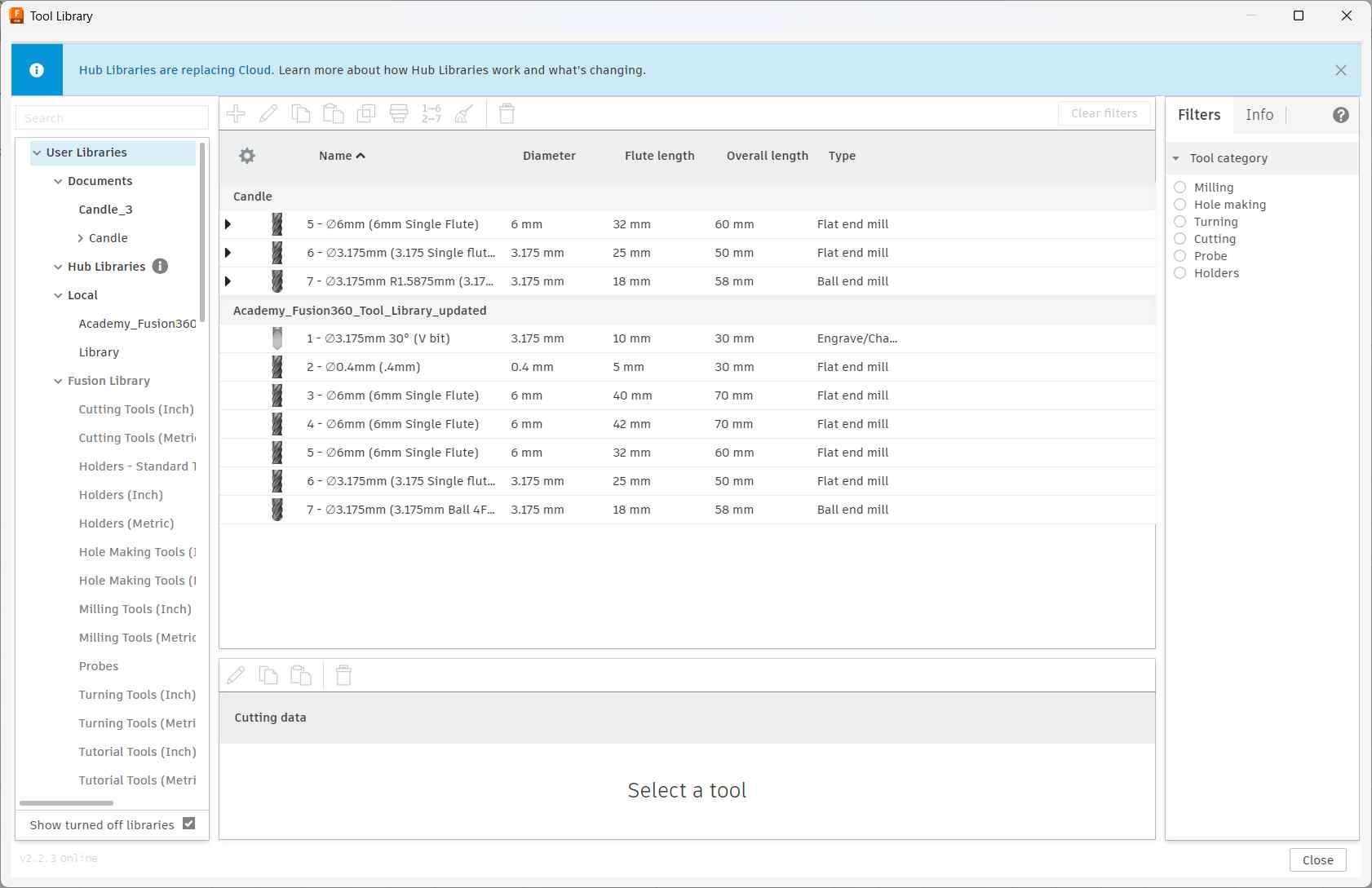
Before creating any toolpaths, I needed to set up the correct tools. Rather than manually entering tool dimensions, our lab provided a pre-configured tool library, Academy_Fusion360_Tool_Library_updated, which contains all the bits physically available at the lab with their exact dimensions and cutting data already set.
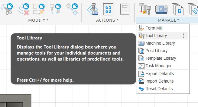
I opened the Tool Library from Manage → Tool Library.
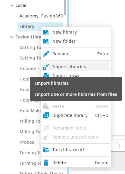
Inside the Tool Library, I right-clicked on Library under the Local section in the left panel and selected Import libraries. This opens a file picker where you can load a .tools library file. The lab had shared their library file which I selected to import.
Once imported, the Academy_Fusion360_Tool_Library_updated library appeared under Local with all seven tools pre-configured with correct dimensions and cutting data:
- Tool 1 — ⌀3.175mm 30° V-bit (Engrave/Chamfer)
- Tool 2 — ⌀0.4mm Flat end mill
- Tool 3 — ⌀6mm Single Flute flat end mill (40mm flute, 70mm overall)
- Tool 4 — ⌀6mm Single Flute flat end mill (42mm flute, 70mm overall)
- Tool 5 — ⌀6mm Single Flute flat end mill (32mm flute, 60mm overall)
- Tool 6 — ⌀3.175mm Single Flute flat end mill (25mm flute, 50mm overall)
- Tool 7 — ⌀3.175mm Ball end mill (18mm flute, 58mm overall)
Having the lab library loaded means I can pick tools by name when setting up operations, and the cutting speeds and feeds are already calibrated for the machines in the lab.
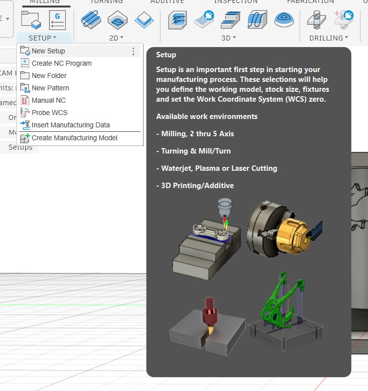
Creating a New Setup
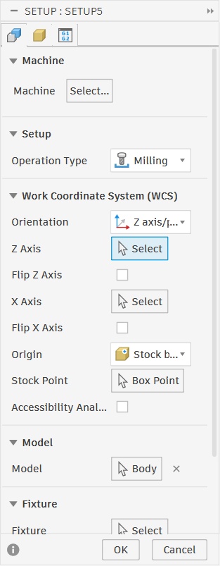
With the tool library loaded, the next step was creating a Setup. In Fusion's Manufacture workspace, a Setup is the first and most important step before generating any toolpaths.
It defines the stock material, the orientation of the part on the machine, and sets the Work Coordinate System (WCS) zero point, which is the reference position the machine uses for all its moves.
I clicked Setup → New Setup to create one.
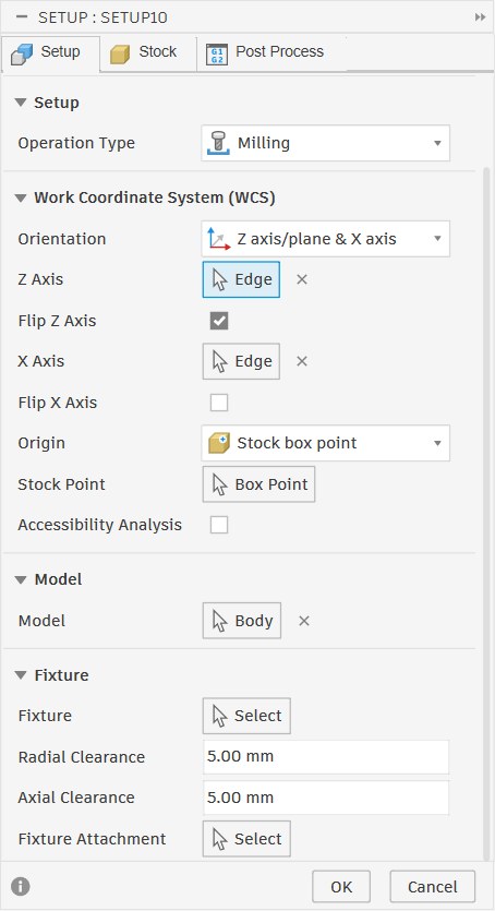
Setting the Stock and WCS Origin
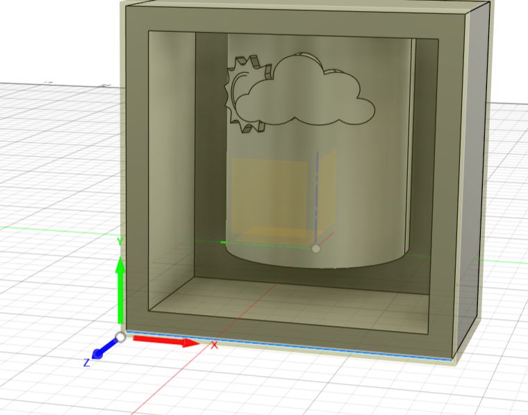
After creating the setup, Fusion displayed the mould model surrounded by a stock bounding box. The tan-coloured box represents the wax block that will be physically placed on the machine bed. The white dots around the corners and edges are the stock point handles, which let you choose where the WCS origin sits.
The WCS origin (shown by the X, Y, Z axis arrows) tells the machine where zero is. By default, Fusion placed the origin near the top of the model.
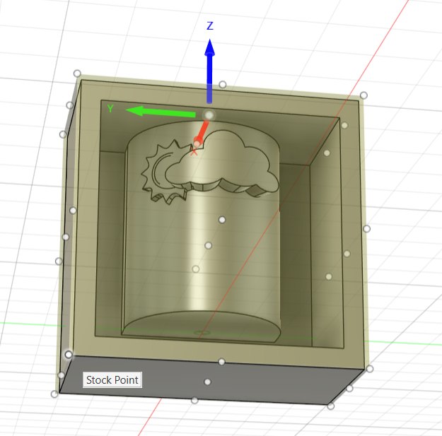
I moved the origin to the bottom-left corner of the stock box.
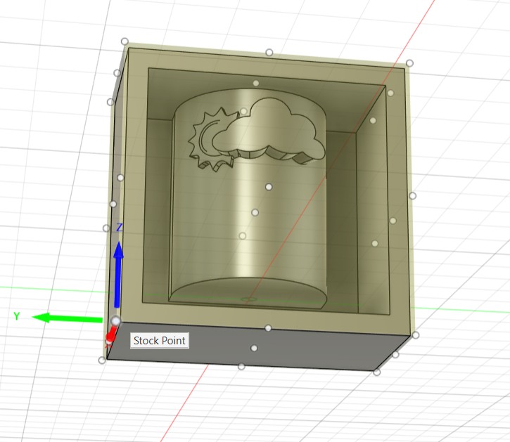
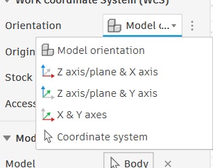
The Orientation dropdown under the WCS section controls how Fusion determines the X, Y, Z axes relative to the model. I opened the dropdown and selected Z axis/plane & X axis. This lets me manually pick an edge or face for the Z axis and another for X.
After selecting that option, the Z Axis and X Axis fields appeared as Select buttons, ready for me to pick edges from the model to define the coordinate system.
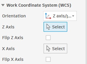
I selected edges from the mould box for both axes.
The 3D view updated to show the WCS origin at the front bottom-left corner of the stock, with X pointing right, Y pointing up, and Z pointing toward the front face making sure that the machine will approach the mould from the correct direction.
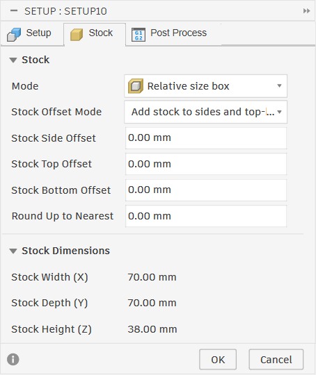
The Stock tab defines the physical wax block the machine will cut into. I set the mode to Relative size box with all offsets at 0 mm so the stock matches the mould body exactly.
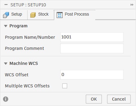
Post Process Settings
The Post Process tab sets the program number that will be written into the G-code file header, and the WCS offset which tells the machine which coordinate offset register to use. I left the program number as 1001 and the WCS offset at 0, which are the standard defaults for the lab machines.
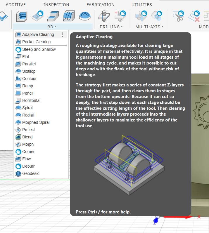
Toolpath Generation
With the setup configured, I moved on to creating the actual toolpaths. I used a 3D Adaptive Clearing strategy, this is a roughing operation designed to remove large amounts of material efficiently while keeping the tool load constant at every stage to avoid breakage.
Adding the Adaptive Clearing Operation
I selected 3D → Adaptive Clearing from the toolbar.
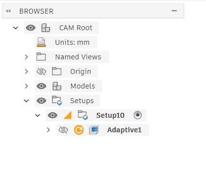
Once created, the operation appeared in the CAM browser as Adaptive1 nested under Setup10, ready to be configured.
Tool — Selecting the Cutter and Feed Rates
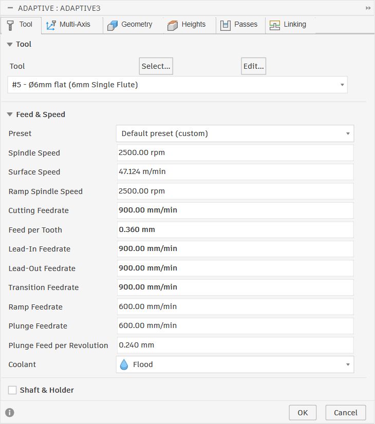
Opening the Adaptive Clearing dialog shows the Tool tab first. This is where I selected the cutter and set the cutting speeds.
I chose tool #5 — Ø6mm flat (6mm Single Flute) from the lab library.
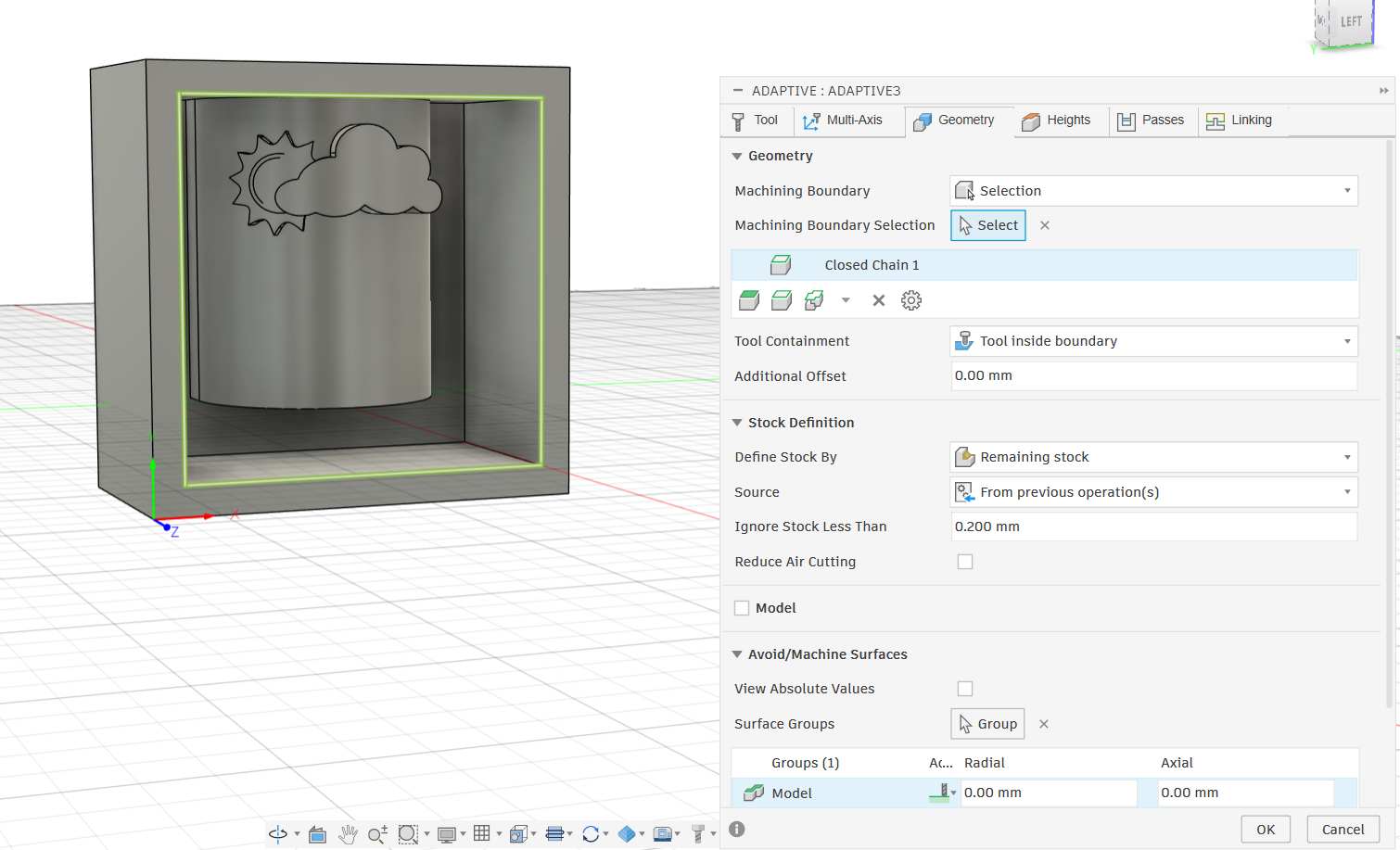
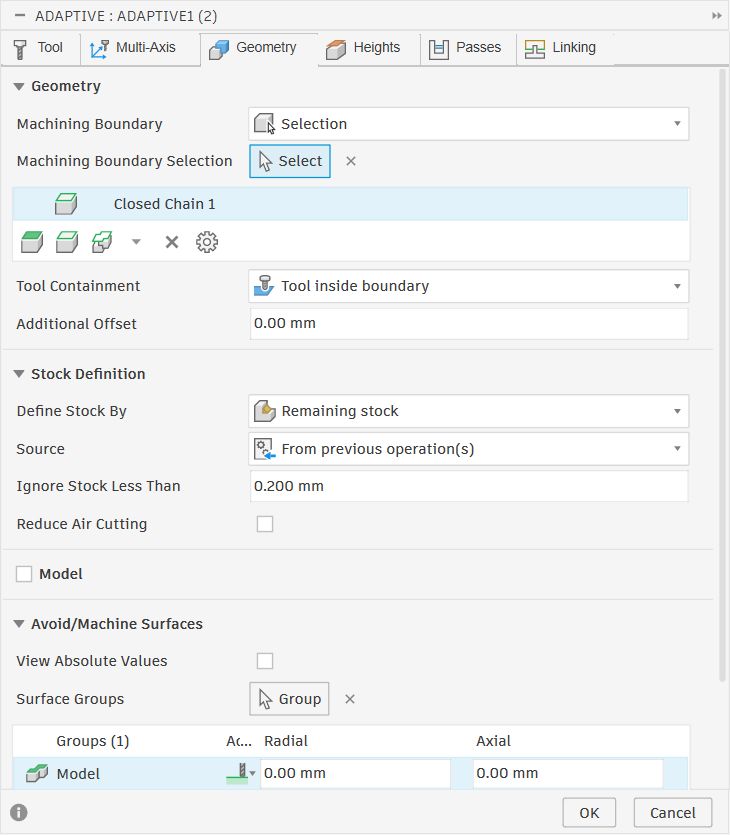
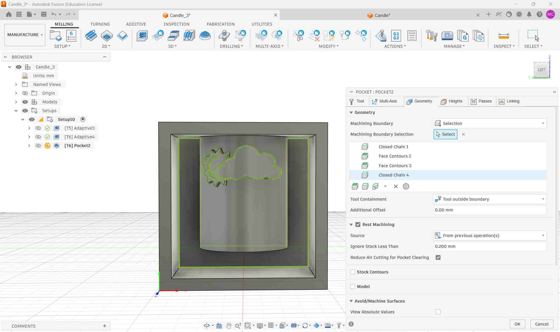
On the Geometry tab I set the machining boundary to the inner rectangle of the mould box cavity. This restricts the tool to the area inside the cavity walls and prevents it from cutting outside the pocket. Tool Containment was set to Tool inside boundary. The stock definition was set to Remaining stock from previous operation(s), so if a second pass is added later it will only cut what is left over.
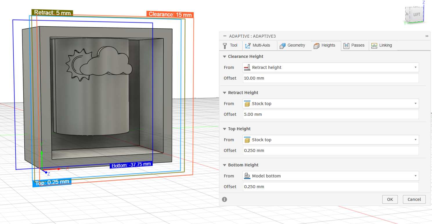
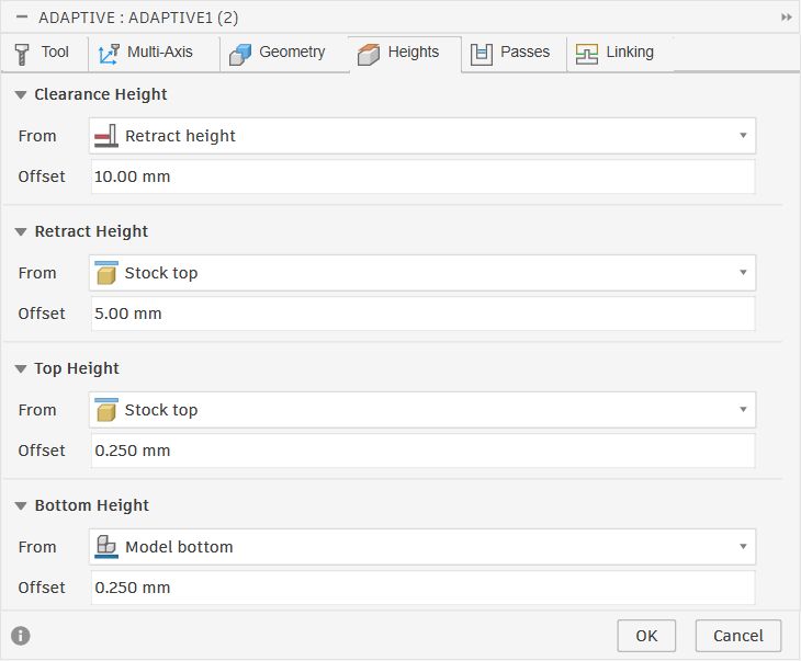
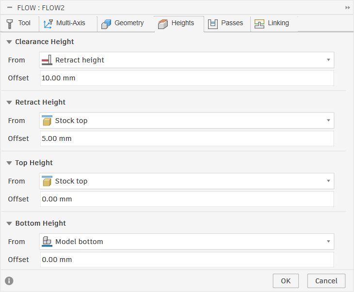
The Heights tab controls how high the tool travels between cuts and how deep it goes. The coloured planes visible in the 3D view correspond directly to these values:
- Clearance Height: Retract height + 10mm — the safe travel height when moving between passes
- Retract Height: Stock top + 5mm — where the tool pulls back to between cuts
- Top Height: Stock top + 0.25mm — where cutting begins, just above the surface
- Bottom Height: Model bottom + 0.25mm — the deepest the tool will go, leaving a thin floor
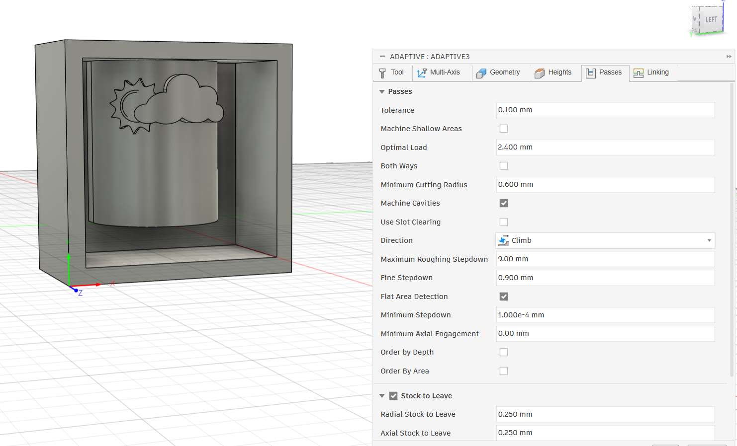
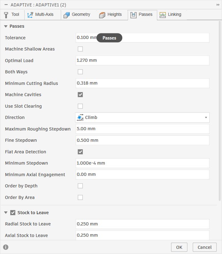
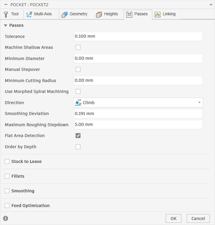
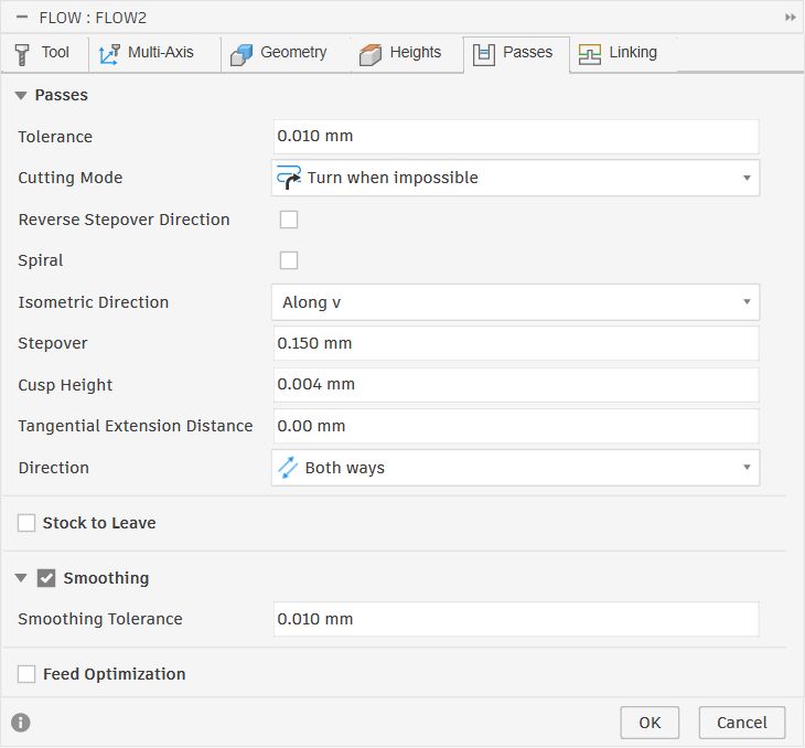
The Passes tab sets how the tool moves through the material on each cut:
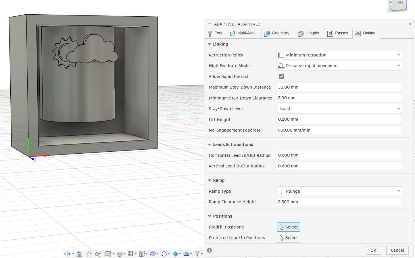
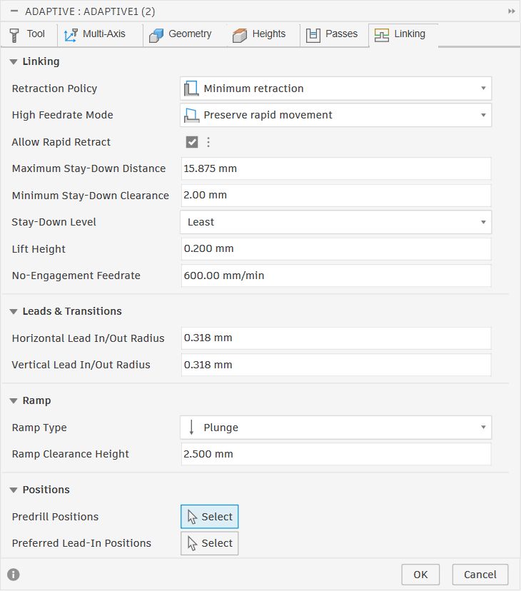
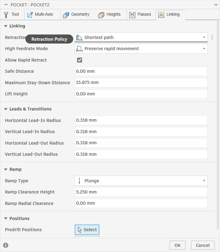
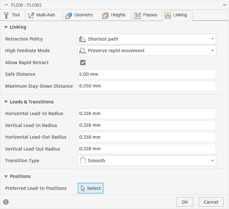
The Linking tab controls how the tool moves when it is not cutting, that is, retracting between passes, leading in and out of cuts, and ramping into the material:
- Retraction Policy: Minimum retraction — keeps the tool as low as possible between passes to reduce air time
- Allow Rapid Retract: enabled — uses rapid feed rate when retracting, speeding up the overall cycle
- Maximum Stay-Down Distance: 30mm — the tool stays down instead of retracting if the next cut is within 30mm
- Lift Height: 0.2mm — tiny lift over obstacles when staying down
- No-Engagement Feedrate: 900 mm/min — feed rate during non-cutting moves
- Ramp Type: Plunge — the tool enters the material by plunging straight down
- Ramp Clearance Height: 2.5mm — how far above the stock the tool positions before plunging
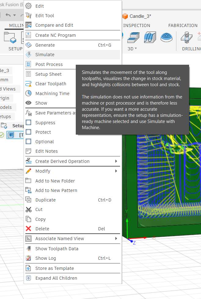
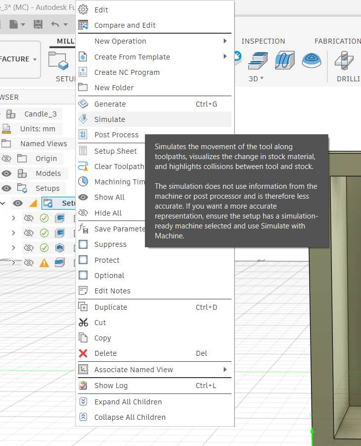
Simulating the Toolpath
With all the tabs configured I right-clicked the operation in the CAM browser and selected Simulate. Fusion's simulation replays the tool moving along every toolpath, shows the material being removed from the stock in real time, and highlights any collisions between the tool and the remaining stock.
Second Adaptive Clearing
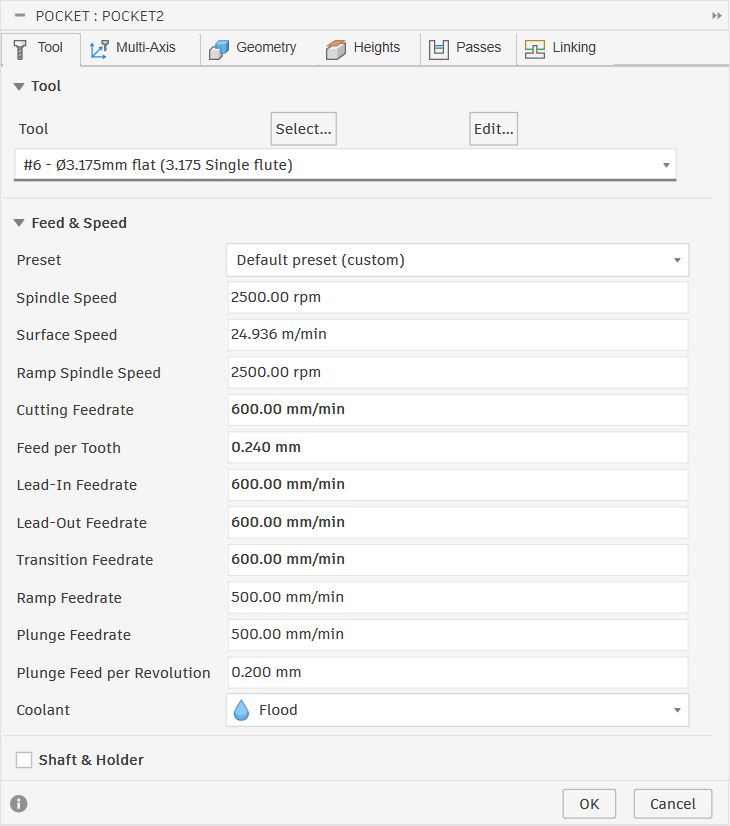
The Ø6mm tool clears the bulk of the wax quickly but its diameter is too large to reach into the tight areas around the embossed cloud and sun details. To machine those zones I added a second Adaptive Clearing operation using the smaller #6 — Ø3.175mm Single Flute tool.
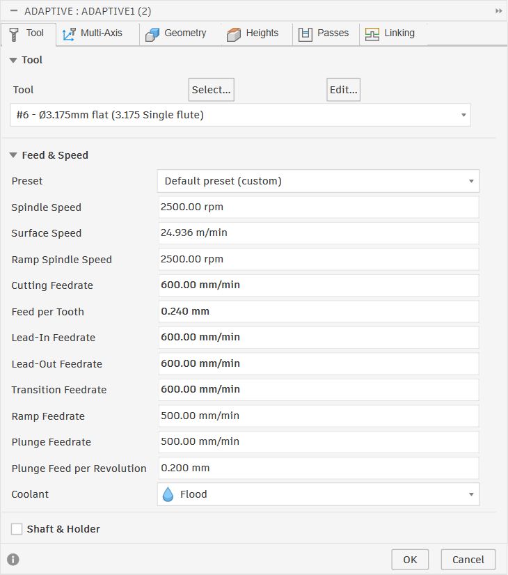
The Passes settings are scaled down for the smaller tool — the optimal load and stepdown values are proportionally reduced to keep chip load safe on the 3.175mm cutter.
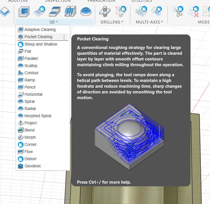
Pocket Clearing — Decoration Edges
I added a third operation — 3D Pocket Clearing — to clean up the material immediately around the embossed cloud and sun outlines. Adaptive Clearing can leave small ridges next to raised features because the tool steps over in wide arcs. Pocket Clearing traces the boundary contours directly with smooth offset passes, which removes those leftover cusps cleanly.

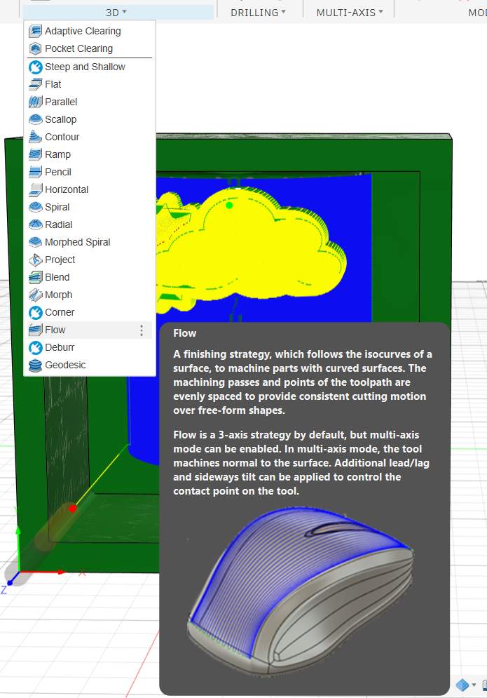
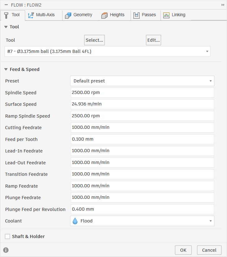
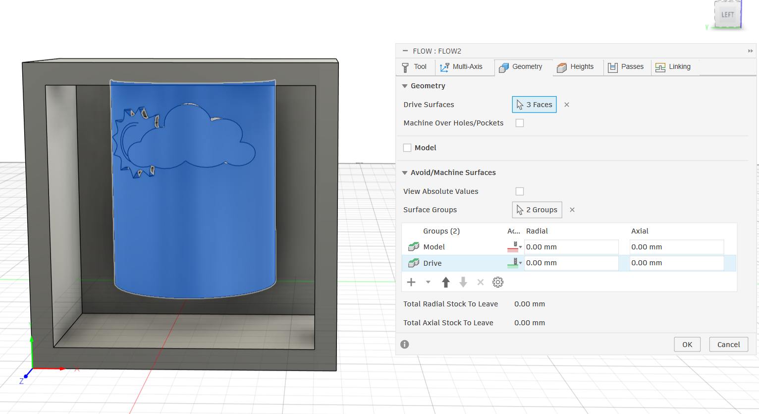
Flow — Surface Finish
The final operation was a Flow finishing pass using the #7 — Ø3.175mm ball end mill. Flow follows the isocurves of the selected surfaces with evenly spaced passes, which produces a smooth finish on curved geometry. I targeted the three curved faces of the candle body with a 0.15mm stepover and 0.01mm tolerance to bring the surface quality up to a level that will produce a clean silicone impression.
Full Simulation
With all four operations configured, I right-clicked Setup10 in the CAM browser and selected Simulate to run the entire toolpath sequence in one pass.
Machine Setup & Milling
With the toolpaths verified in simulation, I moved to the CNC milling machine.
The Machine — TRAK DPM RX2
The machine used for milling the wax mould is the TRAK DPM RX2, a bed mill with a built-in ProtoTRAK RMX CNC control system made by Southwestern Industries.
| Specification | Value |
|---|---|
| Table Size | 49" × 9" (1245 × 229 mm) |
| X / Y / Z Travel | 31" × 16" × 22" (787 × 406 × 559 mm) |
| Quill Travel | 5" (127 mm) |
| Spindle Taper | R8 |
| Spindle Speed Range | 40 – 600 RPM (low) / 300 – 5000 RPM (high) |
| Spindle Motor | 3 HP continuous |
| Rapid Traverse (X / Y) | 400 IPM (electronic handwheels) |
| Rapid Traverse (Z) | 250 IPM |
| Max Table Load | 1,320 lbs (599 kg) |
| Head Swivel | ±90° |
| CNC Control | ProtoTRAK RMX |
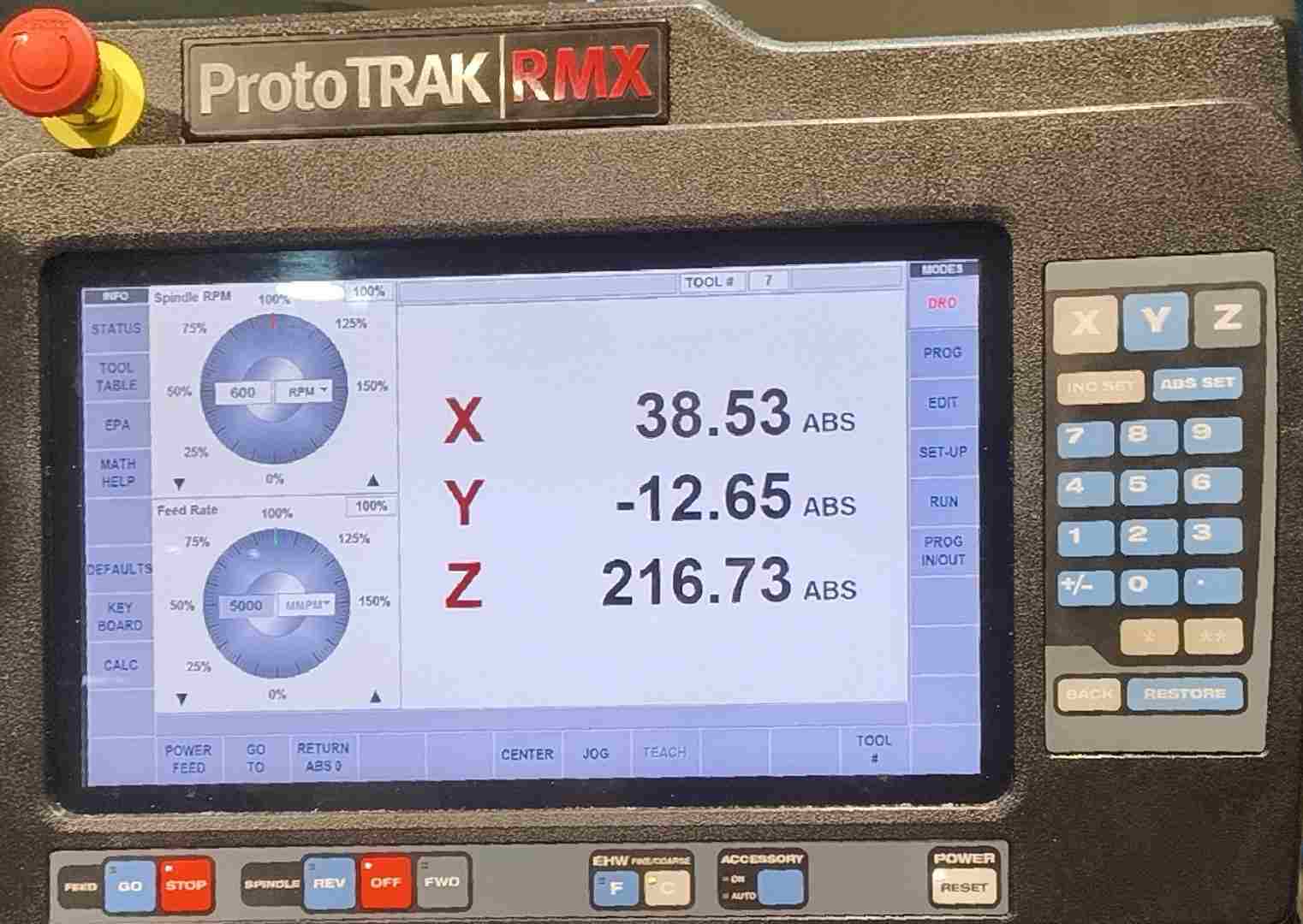
The ProtoTRAK RMX Controller
The ProtoTRAK RMX is a touchscreen panel mounted to the right of the table. It is the brain of the machine — it controls spindle speed, axis movement, and program execution. It has two main operating modes.
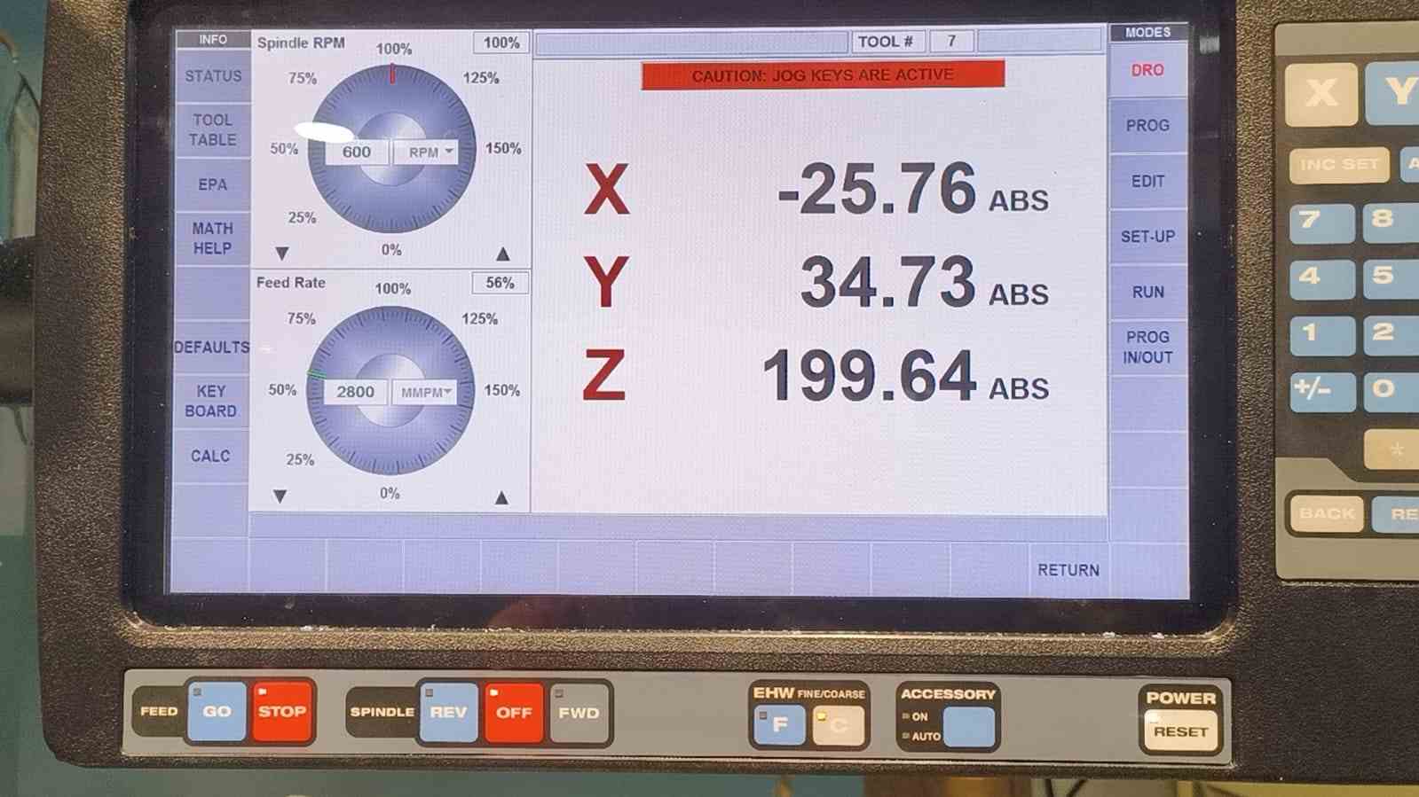
DRO Mode (Digital Read Out)
Acts like a digital readout. The screen shows real-time X, Y, Z coordinates as you move the axes manually. You can set absolute zeros, use power feed, and run basic operations directly from this mode.
If you have never used a CNC machine before, DRO Mode is the easiest place to start.
Think of it this way: the cutting tool is sitting somewhere in 3D space above the table. At any moment, it is at some specific distance from the left edge of your workpiece, some distance from the front edge, and some height above the surface. The DRO screen shows you those three numbers — X (left–right), Y (front–back), and Z (up–down) — live, in real time. The moment you move any axis by turning a handwheel or pressing the on-screen jog buttons, the numbers update instantly.
On its own that is just useful information. But the powerful part is being able to set a zero. At any moment you can press a button and tell the machine: treat wherever the tool is right now as position 0, 0, 0.
After that, every number on the screen becomes a measurement relative to that point. So if you zero at the corner of your wax block and then move the tool 20 mm to the right, the screen shows X = 20.000. Move it 5 mm down into the material, and Z shows −5.000. This is how you connect the real-world position of your workpiece to the coordinate system that your Fusion 360 design was built in.
This is the mode used for all the setup work. Clamping the stock, finding the edges, and zeroing each axis before any program is run.
In DRO Mode you can also use Power Feed to move an axis at a controlled speed automatically, without cranking the handwheel by hand, and set the spindle RPM before starting a cut.
CNC / Run Mode
Once all three axes are zeroed, you switch to Run Mode to execute the G-code file generated by Fusion 360. You load the file from a USB drive, confirm the settings, and press GO. The machine then drives the tool automatically through every move in the toolpath.
A useful feature of the RMX is TRAKing — while the program is running you can turn the handwheels to control the pace of execution. Turning faster speeds the machine up; turning slower slows it down. This is reassuring when running a new program for the first time, since you can slow down before the tool enters a tight area and watch what it does before letting it continue at full speed.
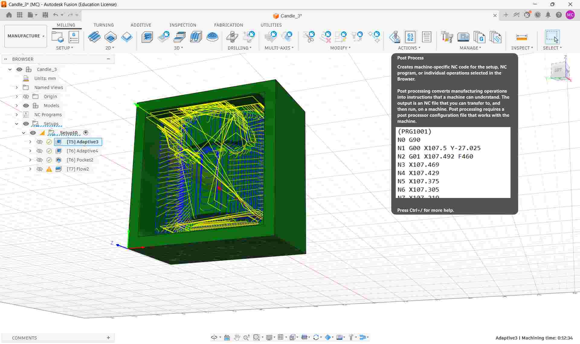
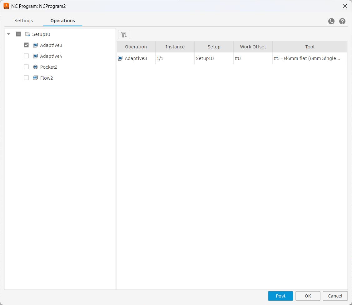
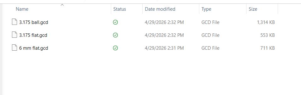
Exporting G-Code from Fusion 360
Before going to the machine, I exported the toolpaths from Fusion 360 as a G-code file. In the Manufacture workspace, I right-clicked Setup10 in the CAM browser and selected Post Process. I selected a compatible post processor for the ProtoTRAK RMX control, set the output folder, and clicked Post. This generated a .nc G-code file that the ProtoTRAK can read directly.
The file was transferred to the machine via USB.
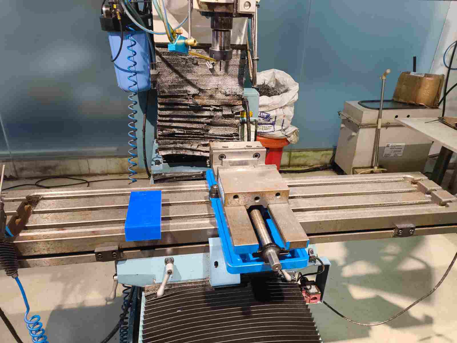
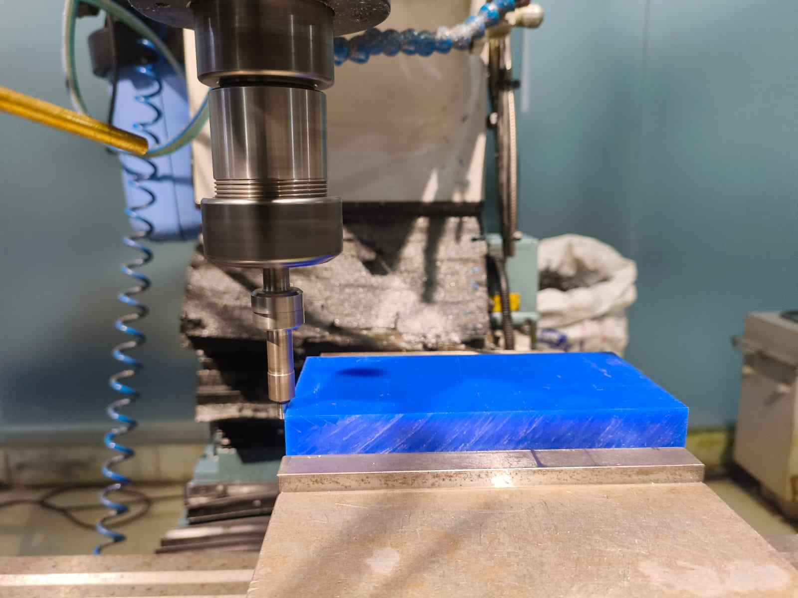
Securing the Wax Block
The first physical step was clamping the wax block securely in the machine vise. The block must not move at all during cutting — any shift mid-program will ruin the part. I made sure the wax was seated flat against the vise jaw and tightened firmly.
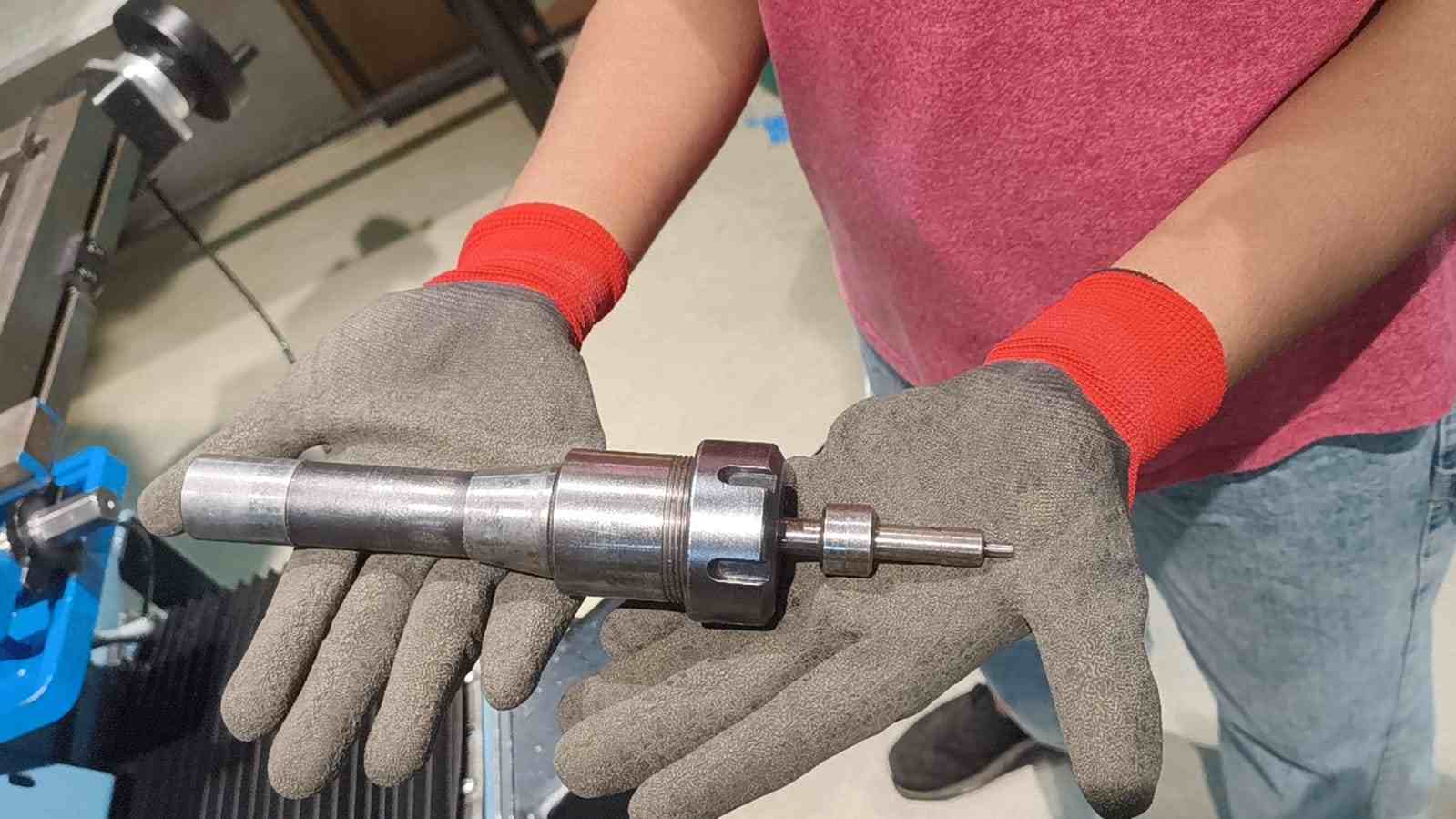
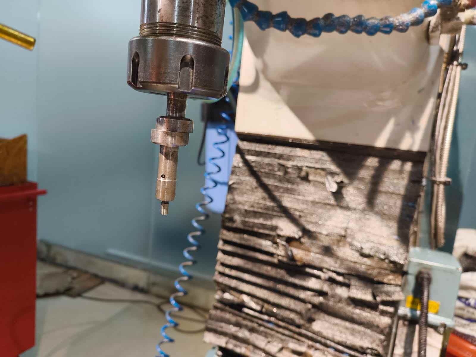
Finding the Work Zero — Edge Finding
With the wax block clamped, the next step was telling the machine where the corner of the block is. This corner is the Work Coordinate System (WCS) origin I set in Fusion 360's Setup, so the machine and the CAD model need to agree on where zero is. I used an edge finder to locate the X and Y edges precisely.
An edge finder is a small cylindrical tool with a spring-loaded tip. When you spin it at a low speed (around 600 RPM) and slowly move it into the edge of the workpiece, the tip snaps to one side the moment it makes contact. That snap is the exact edge position.
The procedure on the ProtoTRAK RMX was as follows:
- Loaded the edge finder into the R8 collet and tightened it.
- On the ProtoTRAK controller, switched to DRO Mode and set the spindle speed to approximately 600 RPM.
- Used the jog controls on the screen to position the edge finder near the front-left corner of the wax block.
- Slowly jogged the X axis until the edge finder tip snapped — this is the X edge of the stock.
- Offset by half the edge finder diameter (typically 5 mm ÷ 2 = 2.5 mm) to account for the tool radius, then pressed SET ABS X = 0 on the controller to zero X at this position.
- Repeated the same process for the Y axis along the adjacent edge of the wax block.
- X and Y absolute zeros are now set to the corner of the wax block, matching the WCS origin from Fusion 360.
Setting the Z Zero
After setting X and Y, I swapped the edge finder for the first cutting tool — the Ø6mm flat end mill. I then set the Z zero at the top surface of the wax block:
- Used the ProtoTRAK screen controls to lower the spindle toward the top of the wax stock.
- Finished the approach manually using the quill handle until the tool just touched the surface.
- Pressed SET ABS Z = 0 on the controller to zero Z at the stock top surface.
- Retracted the quill to a safe height before loading the program.
Loading and Running the Program
With all three axes zeroed, I loaded the G-code file onto the ProtoTRAK:
- Inserted the USB drive containing the exported G-code file.
- On the ProtoTRAK controller, navigated to Programs → Open and selected the file from the USB drive.
- Switched the controller to Run Mode.
- Verified the program start position and confirmed the correct tool was loaded in the spindle.
- Set the feed rate override to a reduced percentage (around 50–60%) for the first run to allow time to monitor the cut.
- Pressed GO to start the program.
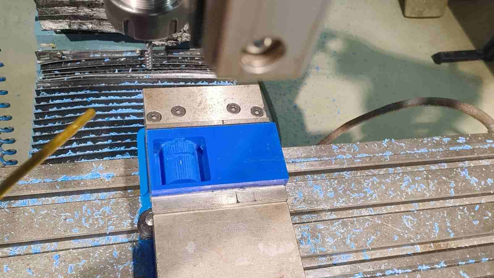
The ProtoTRAK ran through the roughing pass automatically, stepping down through the wax in Z layers while the Adaptive Clearing toolpath removed material in constant-load arcs.
Roughing Pass
The first operation ran the Ø6mm single-flute end mill through the 3D Adaptive Clearing strategy. This removed the bulk of the wax to create the cavity shape, leaving a 0.25 mm stock allowance on all faces for the finishing operations to clean up.
Tool Changes Between Operations
Between each operation, I stopped the program, swapped the tool in the collet, re-zeroed Z for the new tool at the stock surface, then resumed. The X and Y zeros did not need to be reset between tool changes — they remain valid as long as the wax block stays clamped.
Finishing Pass
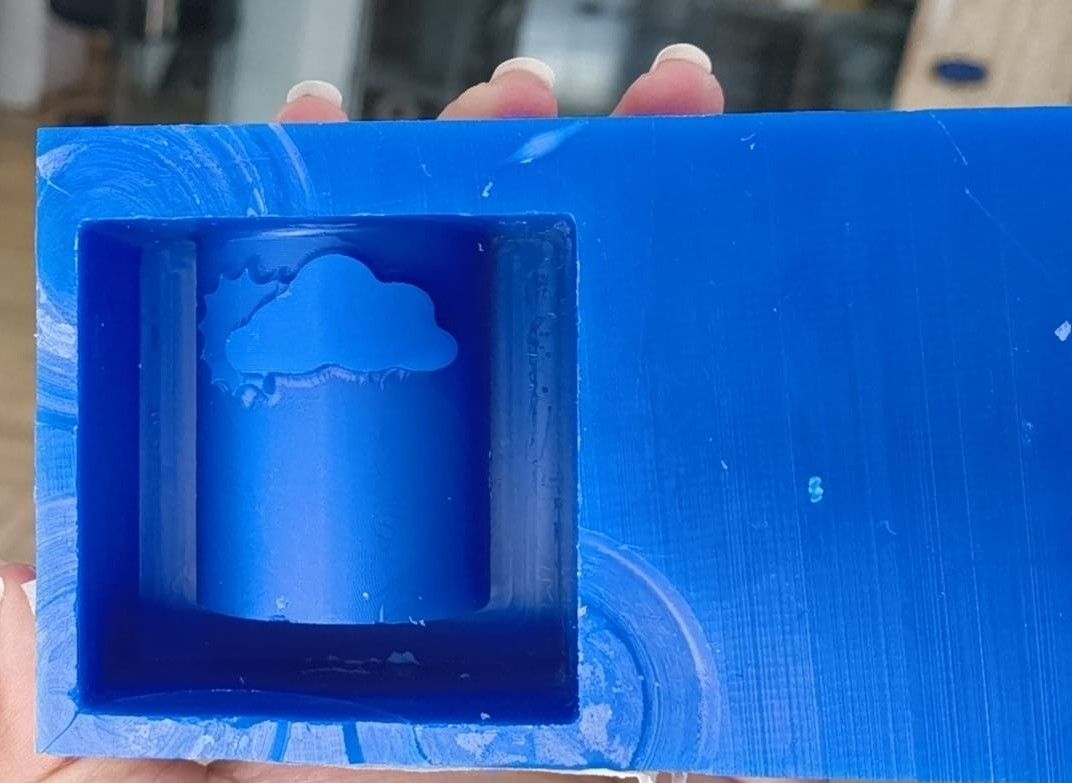
After the adaptive clearing operations, I ran the Flow finishing pass using the Ø3.175mm ball end mill. This pass traced the curved surfaces of the candle cavity with 0.15 mm stepover passes, removing the remaining 0.25 mm stock and producing a smooth surface suitable for clean silicone impression.
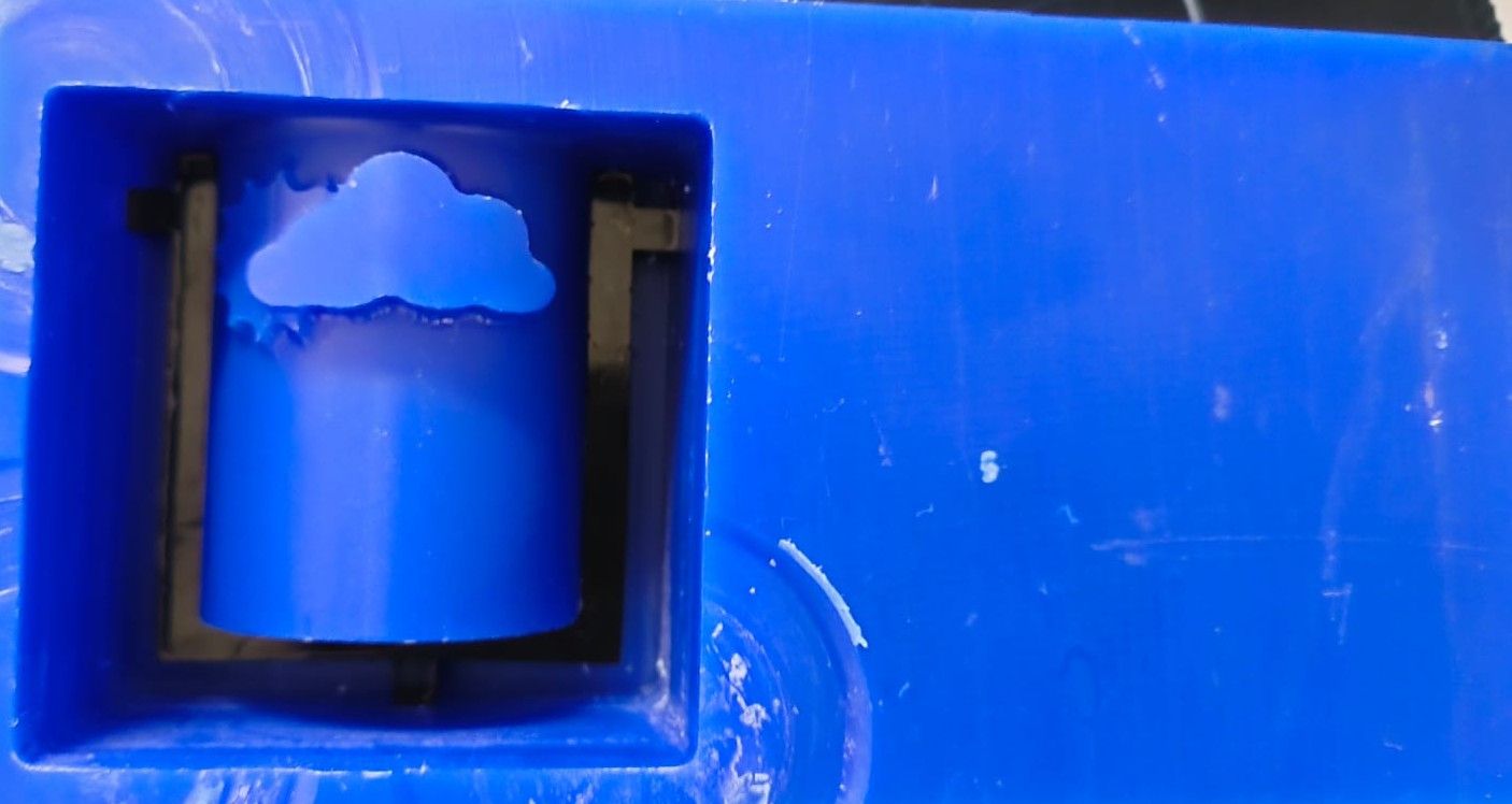
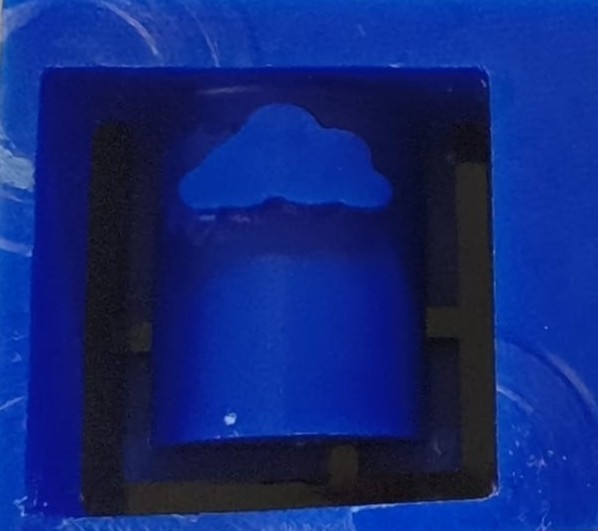
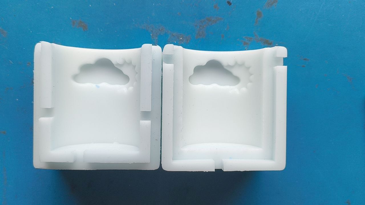
Once both passes were done, the wax mould was complete. The cavity came out clean with no visible tool marks.
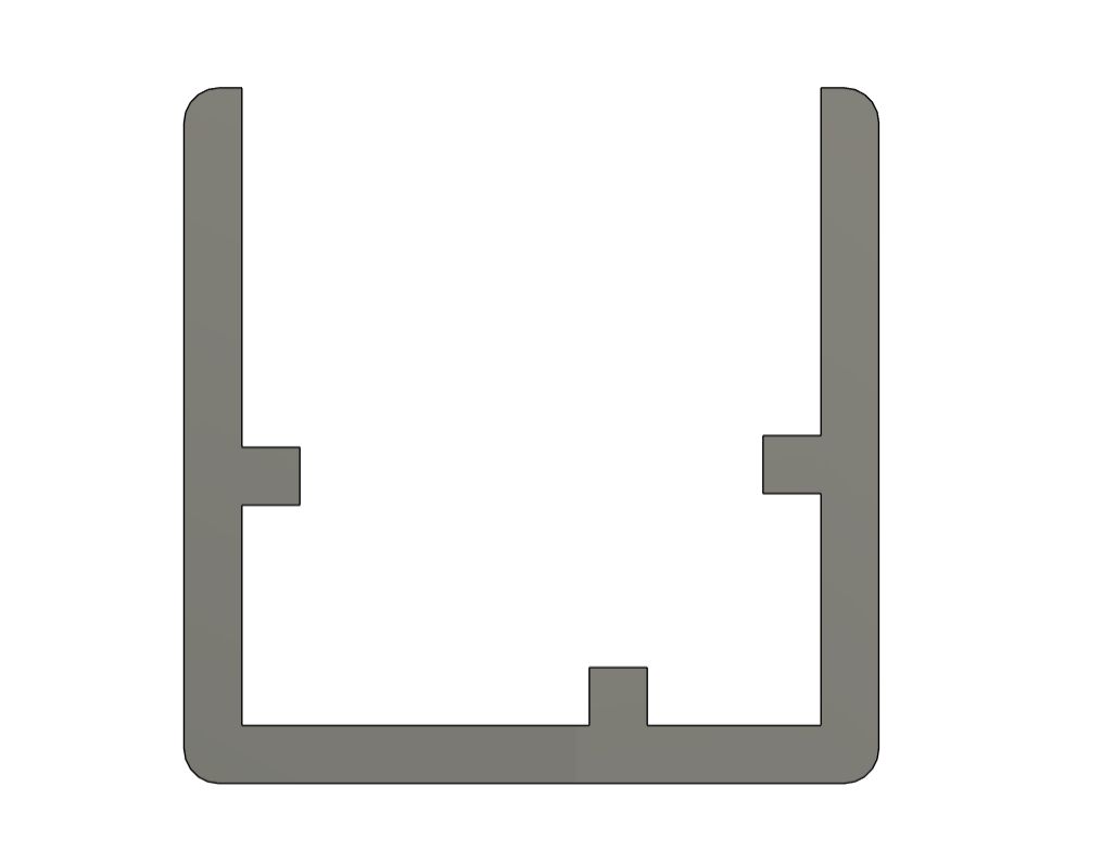
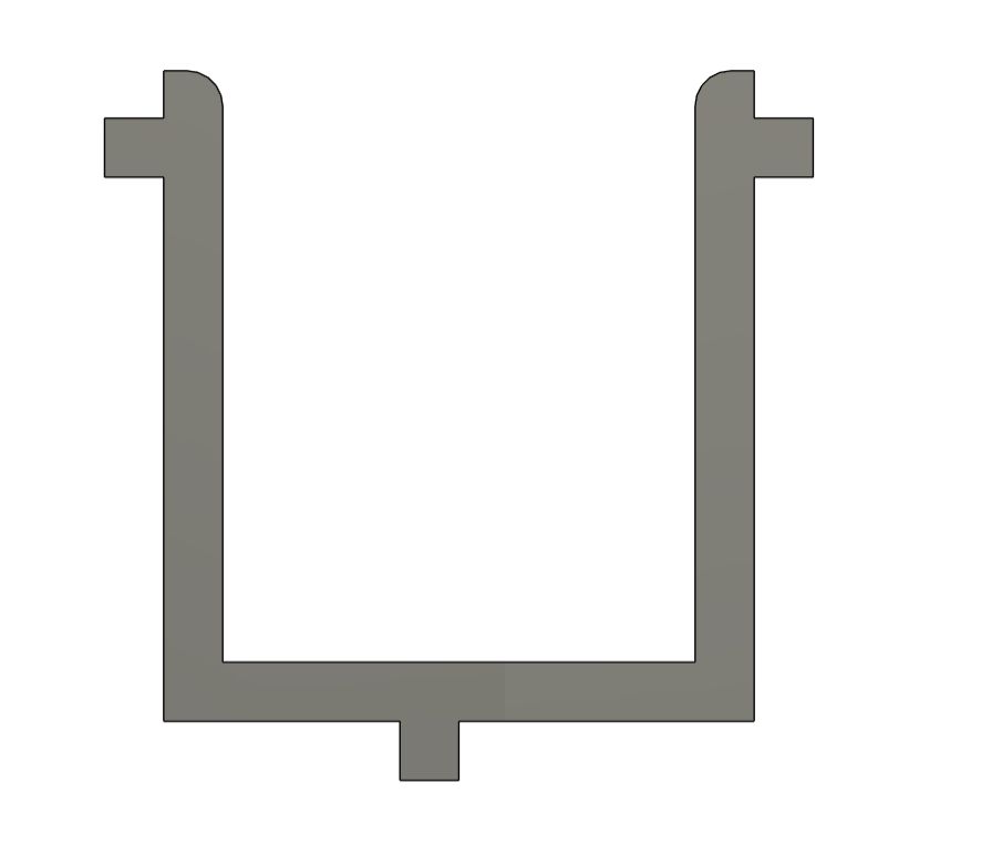
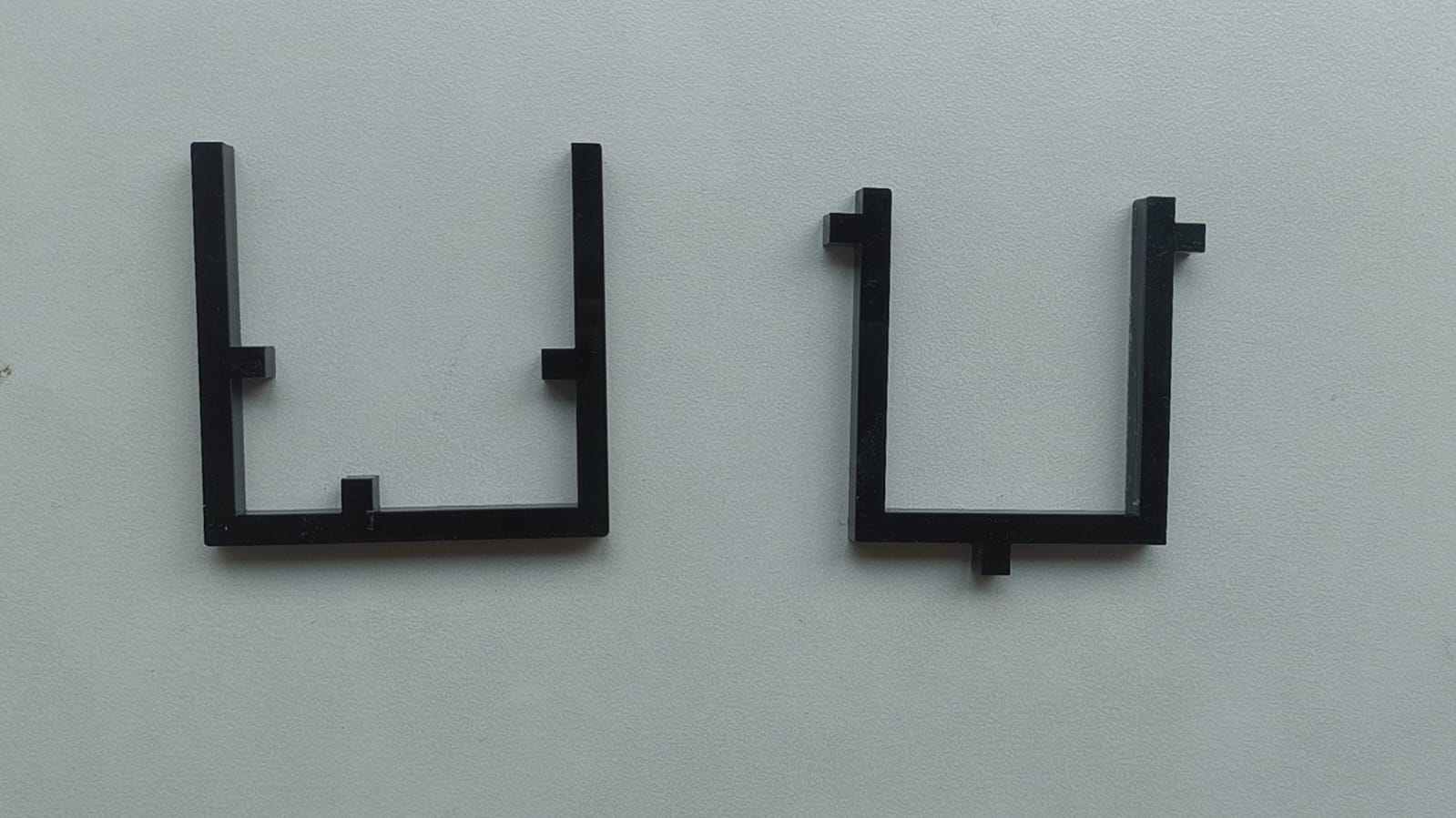
Before pouring the silicone over the mould, I needed a way to hold the two wax halves together when pouring the wax into the silicone. For this, I designed two interlocking acrylic frames in Fusion 360 and laser cut them.
This was done so that the moulds would have joints to lock them together.
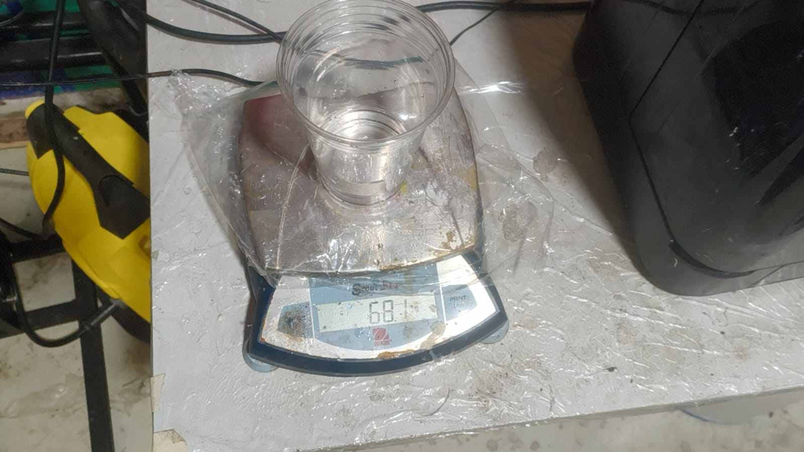
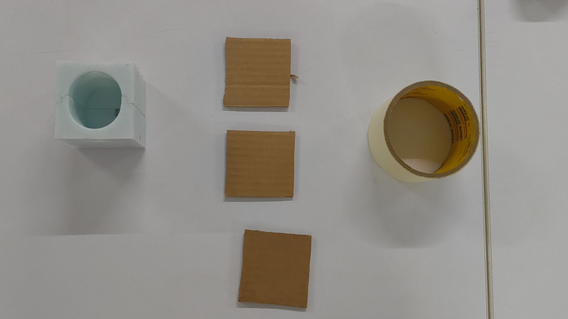
I filled the assembled frame with water first to measure how much silicone I would need before mixing it. Then I poured iut into a transparent glass and marked the water level using a tape.
Then I emptied the glass, made sure there were no water left behind and poured in the silicone.
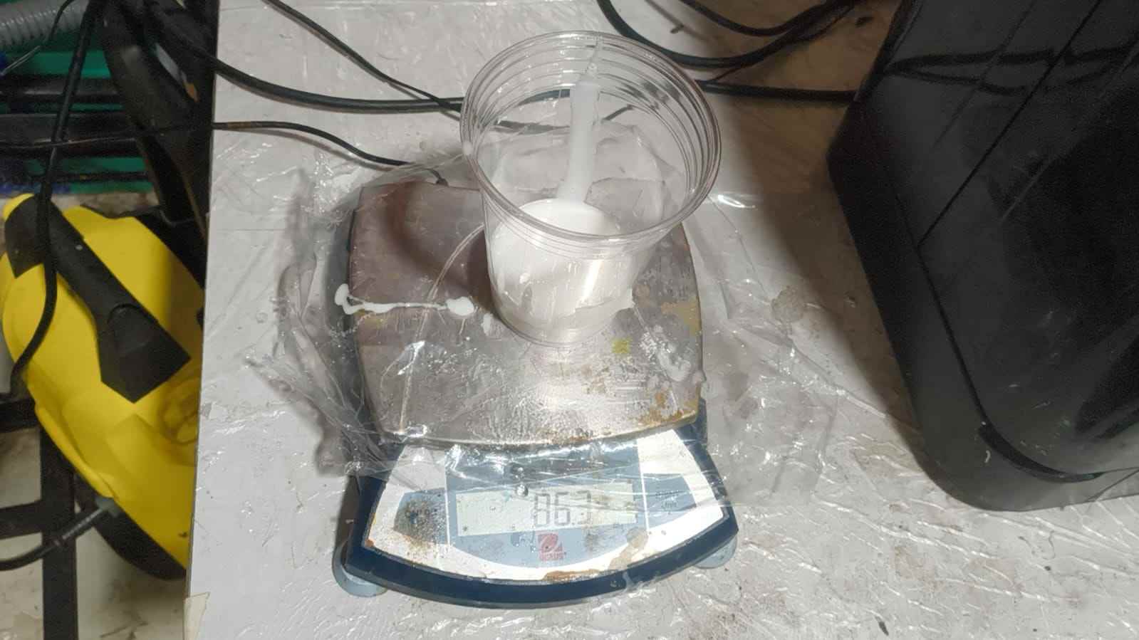
Then I poured the silicone in to the cup.
I had to pout it two times. One with each of the acrylic fixed inside.
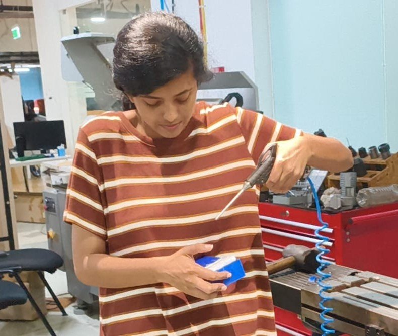
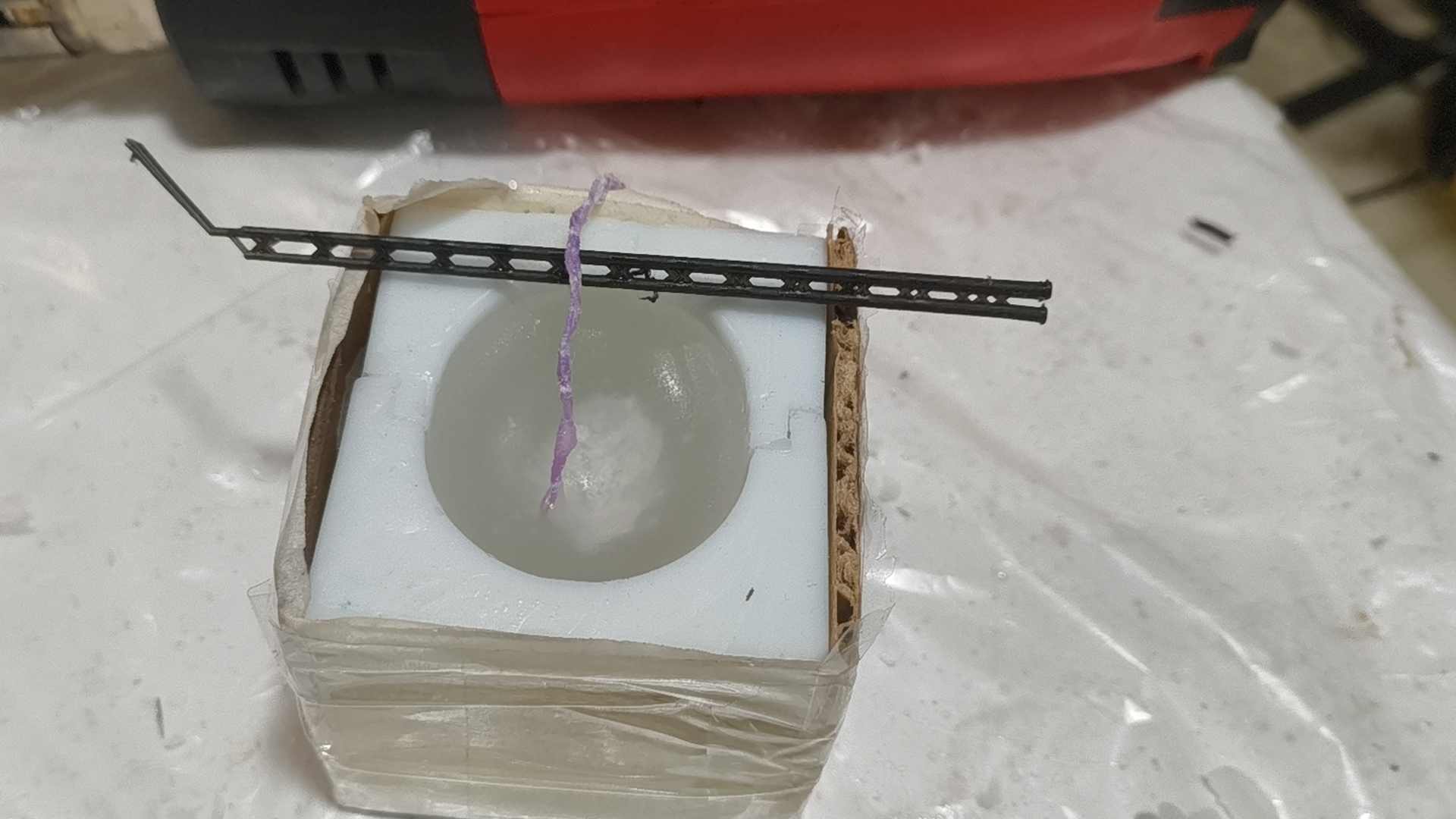
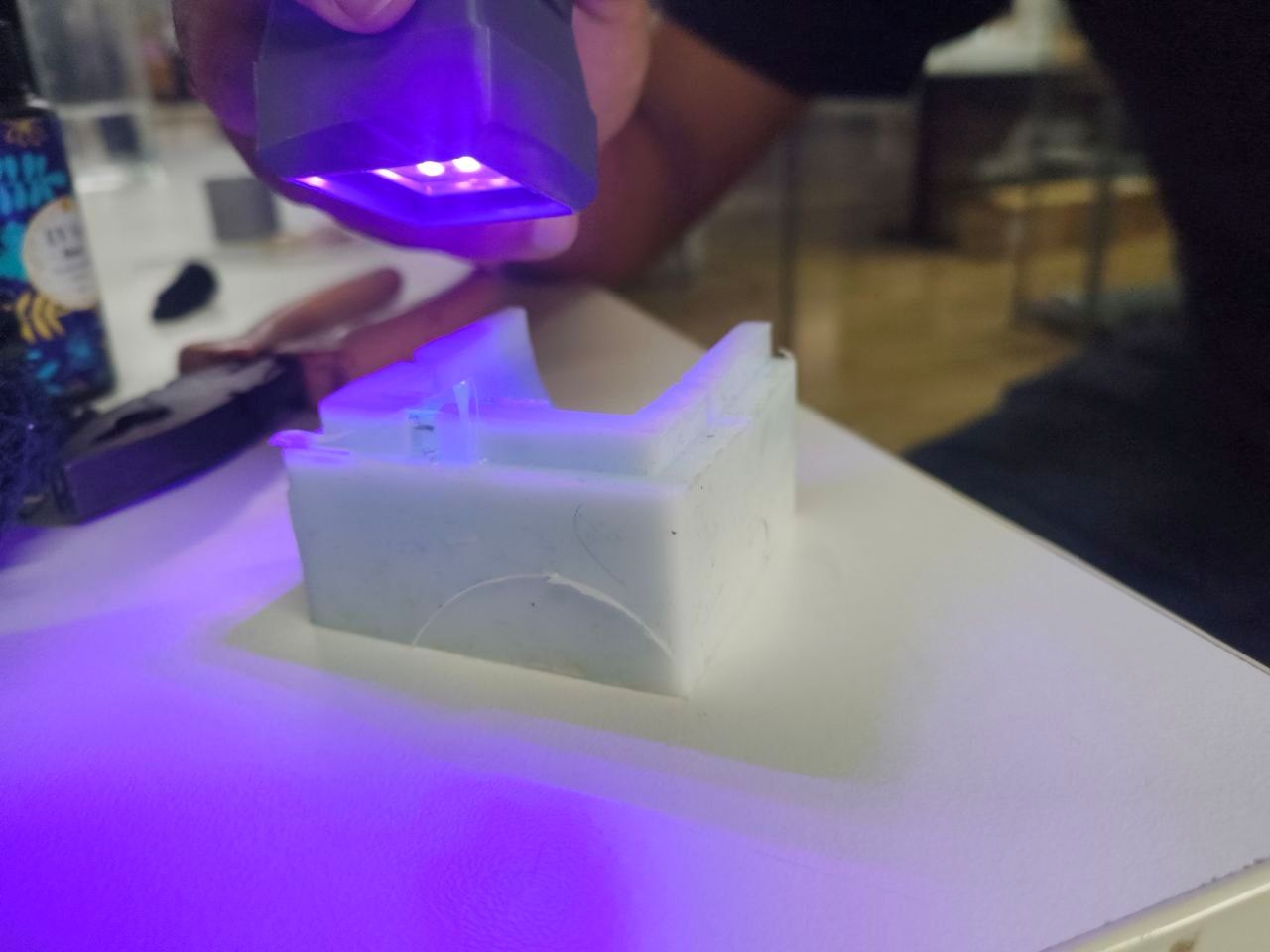
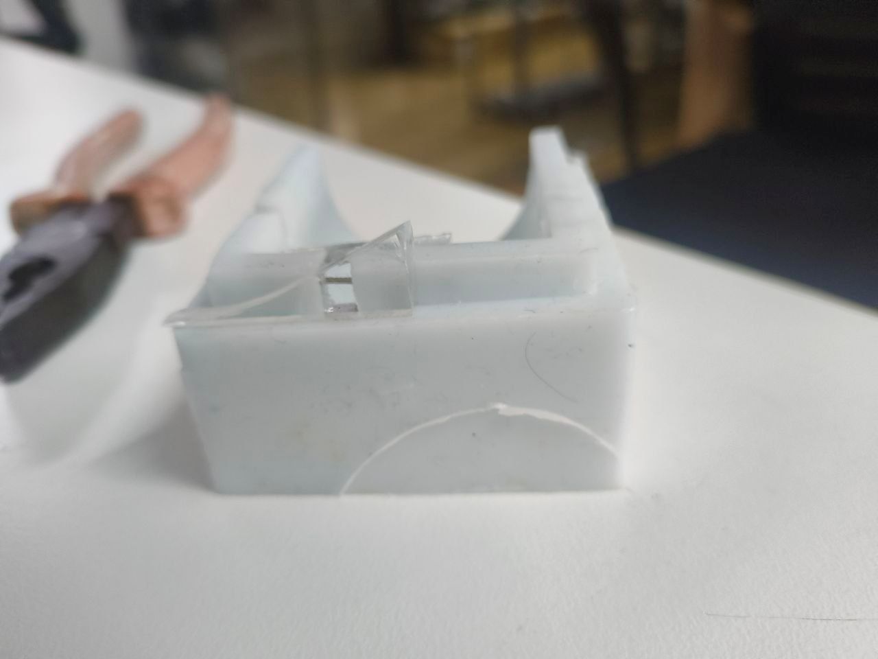
I needed to fill the gaps made by the acrykic in the mould. So I stuck needles between the gap and pured glue over it.
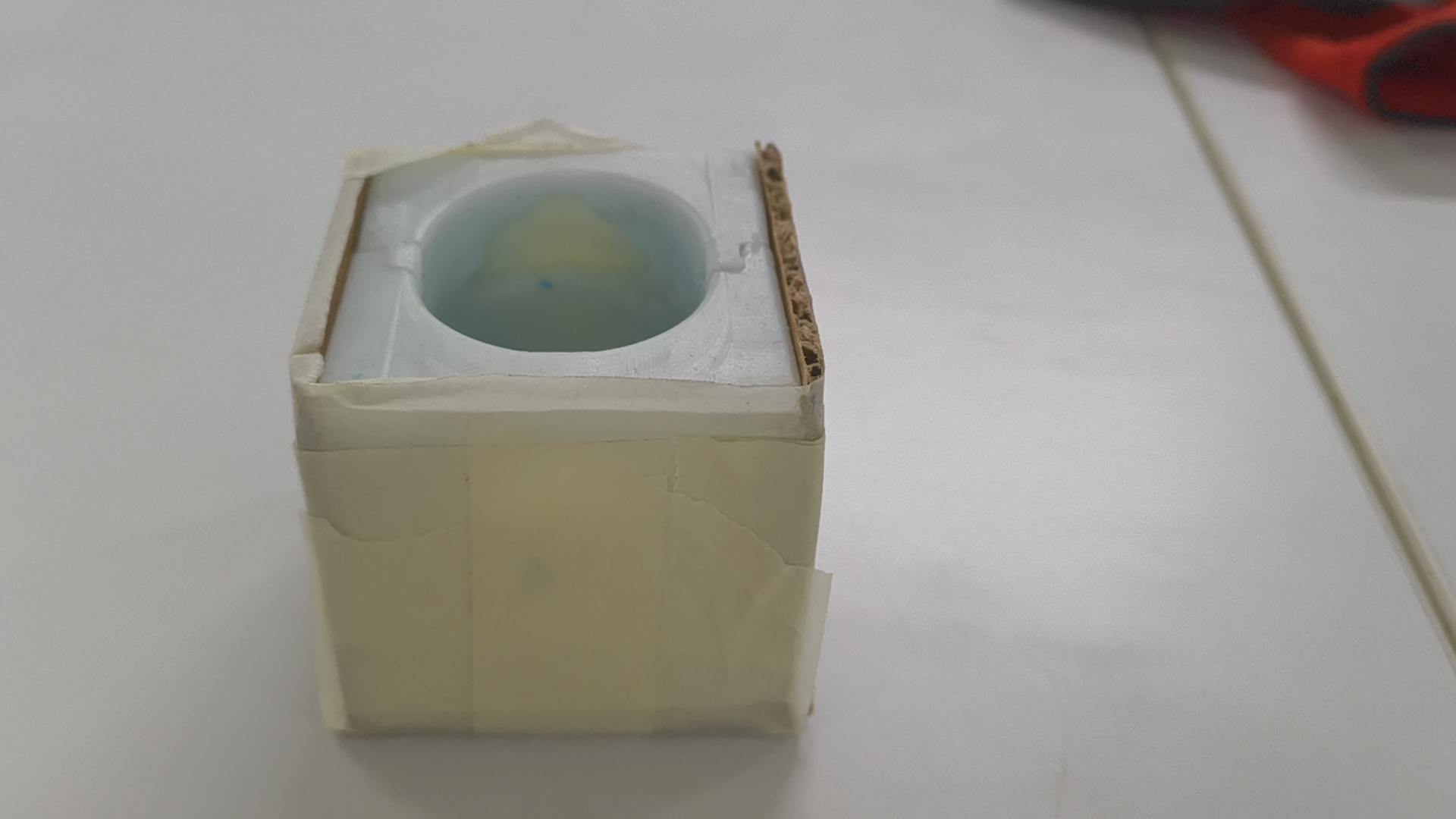
To make sure the wax wont leak, I covered it with filled and masking tape.
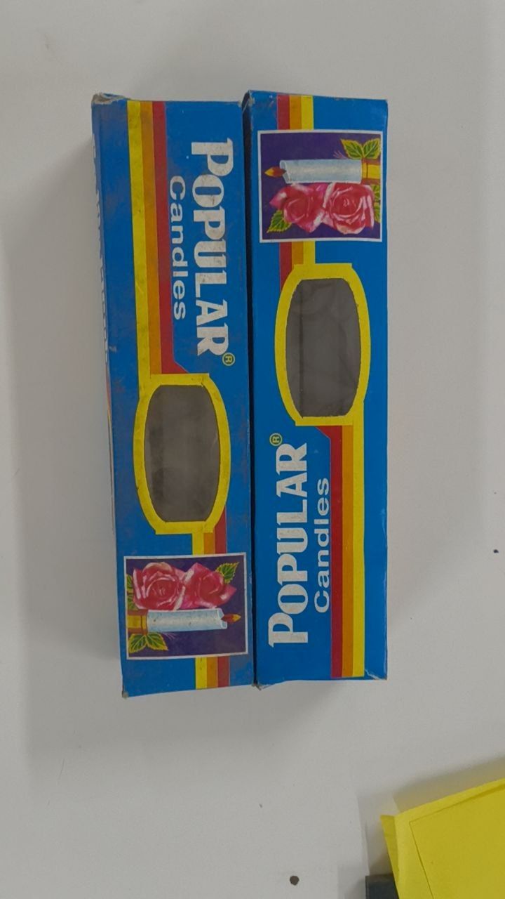
TThese are the candles I brought from a shop. I had to search through a couple of shops to get it.
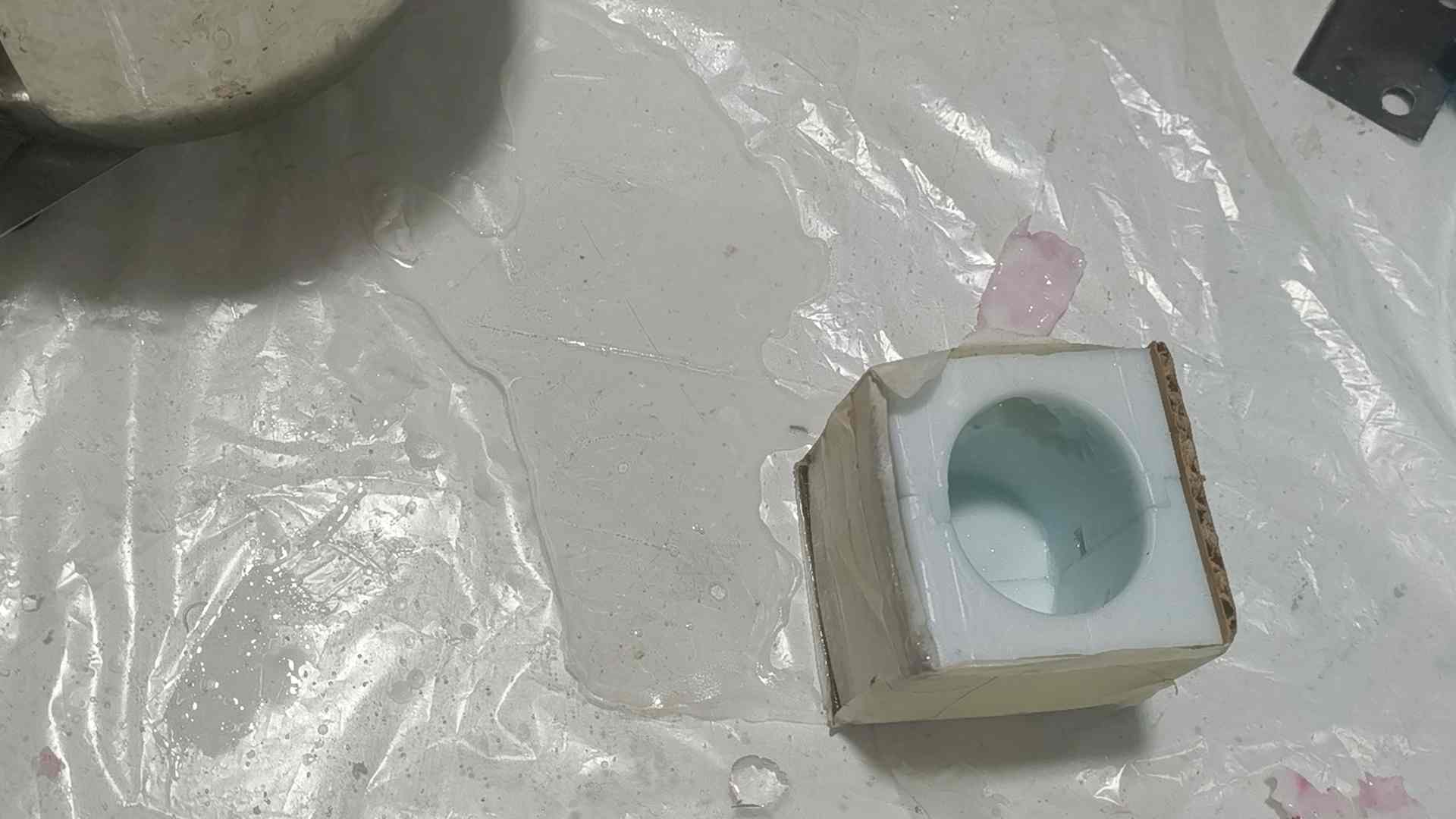
Pouring wax into the mould.
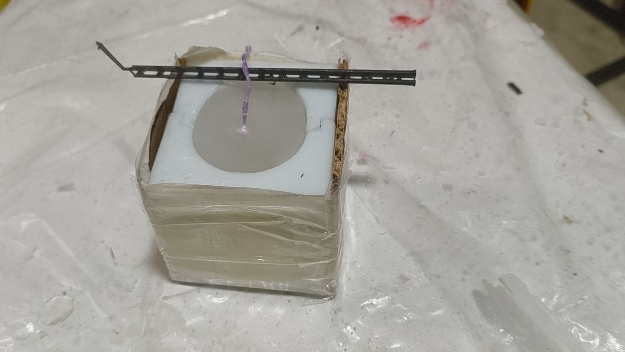
But the wax still leaked. So I covered it with some layers of packaging tape.
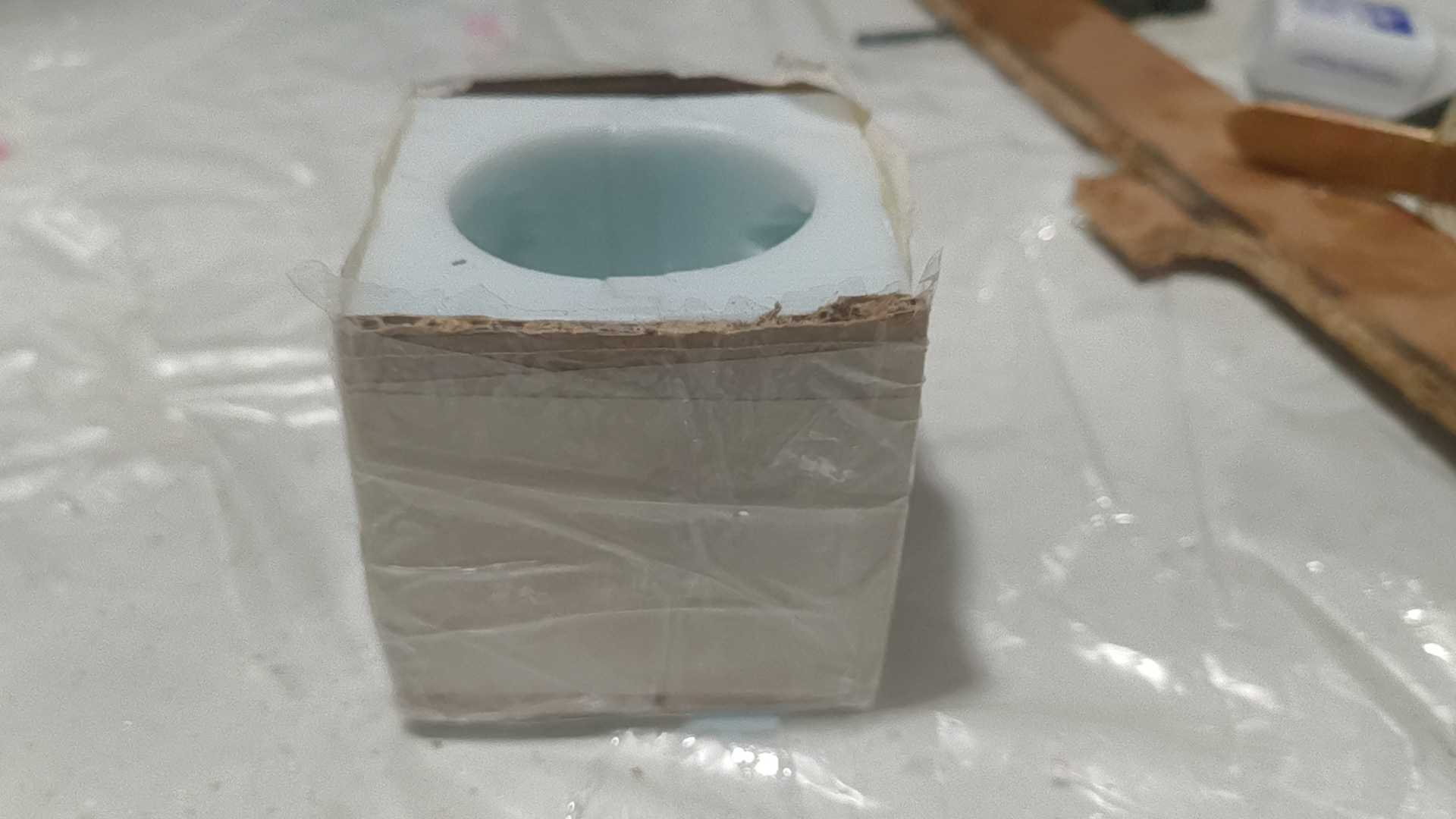
Pouring again.
Hole in the middle. So I poured in a little more.