3D SCANNNG AND PRINTING
Group Assignment
- Test the design rules for your 3D printer(s).
Individual Assignment
- Design, document, and 3D print an object that could not be made subtractively (small, few cm, limited by printer time).
- 3D scan an object (and optionally 3D print it).
In this week, I focused on understanding the difference between subtractive and additive manufacturing by creating a print-in-place design with moving parts and documenting the full workflow from design to print validation. I also explored 3D scanning to compare how physical objects can be captured and converted into digital models for further fabrication.
You can see our Group Assignment here
Bambu Lab A1
The Bambu Lab A1 is an advanced desktop FDM 3D printer designed to deliver high speed, precision, and automation. It is suitable for both beginners and experienced users due to its intelligent calibration features and easy-to-use interface. The printer uses a modern motion system and built-in sensors to automatically adjust printing parameters, improving reliability and print quality.
Key Features of Bambu Lab A1
| Feature | Description |
|---|---|
| Automatic Z-Offset Calibration | Automatically measures and adjusts nozzle distance from the build plate. |
| Automatic Flow Calibration | Automatically tunes extrusion settings for consistent filament flow. |
| Vibration Compensation System | Detects vibration and adjusts motion settings to improve surface finish. |
| Automatic Belt Adjustment | Monitors belt tension and maintains stable performance. |
| Automatic Filament Handling | Simplifies filament loading and unloading from the printer interface. |
| Multi-Color Printing Support | Supports multi-color prints when connected to AMS Lite. |
| Real-Time Extrusion Monitoring | Tracks extrusion behavior for print consistency. |
| Noise Reduction System | Uses optimized motor control to reduce operating noise. |
| High-Speed Printing Capability | Prints faster while maintaining dimensional accuracy. |
| User-Friendly Interface | Touchscreen display for easy control and monitoring. |
| Offline Printing Capability | Supports local operation without internet connectivity. |
Technical Specifications of Bambu Lab A1
| Specification | Details |
|---|---|
| Build Volume | 256 x 256 x 256 mm |
| Printing Technology | Fused Deposition Modeling (FDM) |
| Motion System | CoreXY motion system |
| Filament Diameter | 1.75 mm |
| Nozzle Diameter | 0.4 mm (standard), optional sizes available |
| Maximum Nozzle Temperature | 300°C |
| Maximum Bed Temperature | 100°C |
| Supported Materials | PLA, PETG, TPU, ABS, ASA, Nylon, and others |
| Layer Height Range | 0.08 mm to 0.28 mm |
| Maximum Print Speed | Up to 500 mm/s |
| Build Plate Type | PEI spring steel plate |
| Sensors | Filament run-out sensor, extrusion monitoring sensor |
| Recovery Feature | Supports resume printing after power loss |
Source: Bambu Lab A1 Technical Document
These specifications make the printer suitable for both rapid prototyping and functional part production.
Subtractive and Additive Manufacturing
Subtractive Manufacturing
Subtractive manufacturing is a process in which material is removed from a solid block to obtain the final shape. Common examples include milling, turning, drilling, and CNC machining.
In subtractive processes, the object is produced by cutting away unwanted material. The final geometry is limited by tool access, tool diameter, and the ability to reach internal features.
Characteristics
- Material is removed from a larger stock.
- Internal cavities are difficult or impossible without assembly.
- Tool access determines achievable geometry.
- Often produces strong and accurate parts.
- Generates material waste.
The movable fidget ring designed in this assignment cannot be manufactured as a single piece using subtractive methods because the nested internal rings would require separate fabrication and mechanical assembly.
Additive Manufacturing
Additive manufacturing, commonly known as 3D printing, is a process where material is deposited layer by layer to build an object from the bottom up.
Unlike subtractive manufacturing, additive processes allow the creation of internal geometries, enclosed cavities, and interlocking parts without assembly.
Characteristics
- Material is added layer by layer.
- Complex internal structures are possible.
- Minimal material waste compared to subtractive methods.
- Design freedom is significantly higher.
- Layer bonding affects mechanical strength.
The fidget ring mechanism is an example of a print-in-place design, where all moving components are fabricated simultaneously in one print. The 1 mm clearance between rings allows motion after printing, without the need for assembly.
Comparison
| Aspect | Subtractive Manufacturing | Additive Manufacturing |
|---|---|---|
| Material Usage | Removes material from stock | Adds material layer by layer |
| Internal Moving Parts | Requires assembly | Can be printed in place |
| Design Freedom | Limited by tool access | High geometric freedom |
| Suitability for This Design | Not feasible as one piece | Fully feasible as single print |
Conclusion
This project clearly demonstrates the advantage of additive manufacturing over subtractive manufacturing for complex interlocking mechanisms. The nested rings of the fidget spinner can only function as a single printed unit because additive manufacturing enables the fabrication of internal moving parts without assembly.
Design Rules
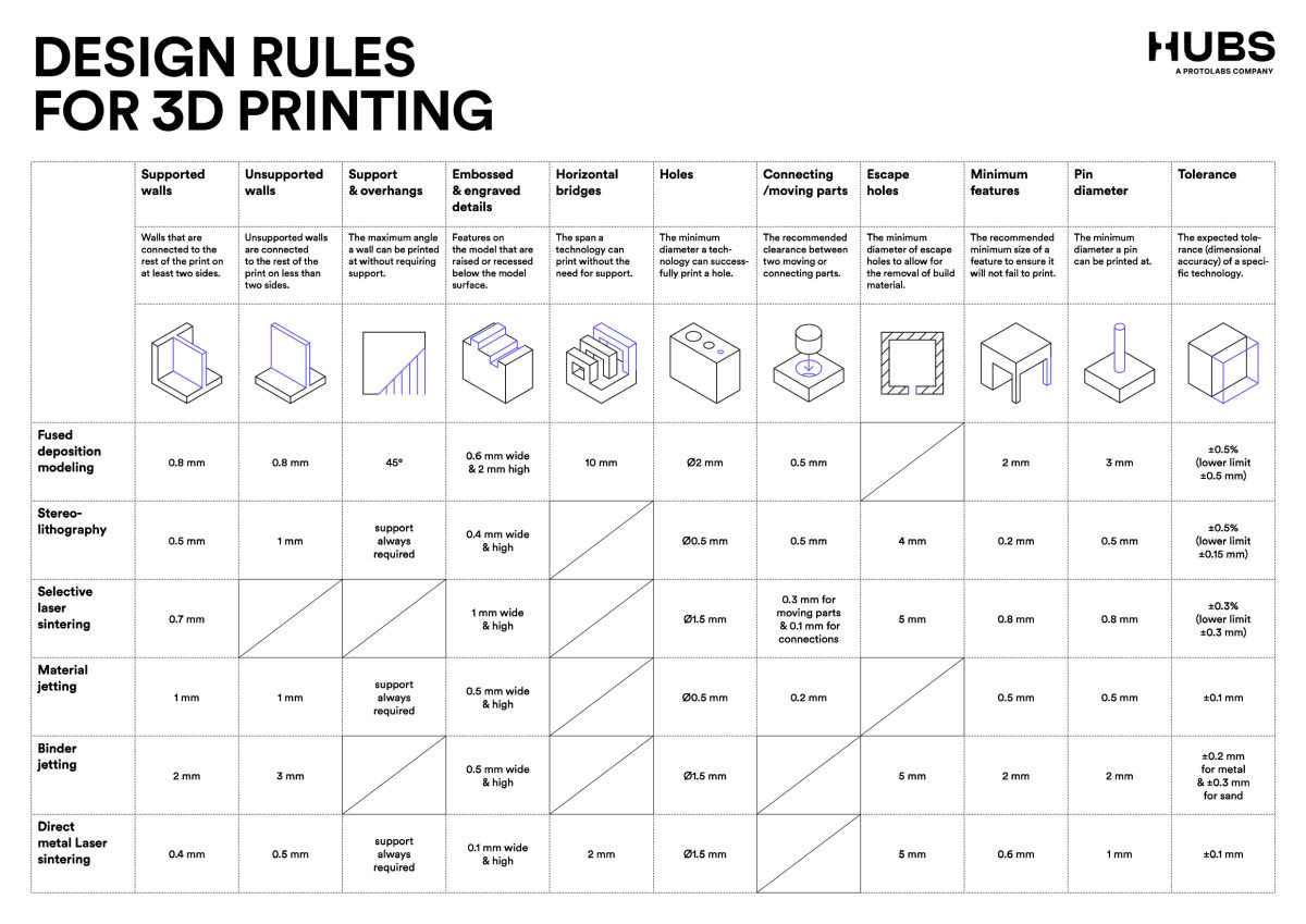
Overhangs
An overhang is a portion of a printed part that extends outward with no direct support beneath it. Since FDM printing deposits molten filament layer by layer, unsupported material can sag due to gravity.
Most FDM printers can reliably print overhangs up to approximately 45° from the vertical without requiring support.
Typical Guidelines
- 0–45° → Usually prints cleanly without support
- 45–60° → May show slight drooping
- Above 60° → Supports are typically required
Why 45° Works
Each new layer slightly overlaps the previous one. At 45°, enough of the new filament rests on the previous layer to maintain structural stability.
Factors Affecting Overhang Quality
- Cooling efficiency (part cooling fan strength)
- Print speed
- Layer height
- Material type (PLA handles overhangs better than ABS)
- Extrusion temperature
Lower temperatures and better cooling improve overhang performance.
Supports
Supports are temporary printed structures used to hold up overhanging or unsupported features during printing.
Supports are generated in the slicer software and are printed using the same material as the model (unless dual extrusion is available).
Purpose of Supports
- Prevent collapsing of steep overhangs
- Maintain dimensional accuracy
- Reduce sagging and distortion
Types of Supports
- Grid/Lattice Supports → Strong, easier to generate
- Tree Supports → Use less material, easier to remove, better surface finish
- Line Supports → Faster to print but less stable
Support Considerations
- Higher support density increases stability but makes removal harder
- Support interface layers improve surface finish
- Excessive supports increase print time and material usage
Supports must be removed carefully after printing to avoid damaging the surface.
Bridging
Bridging occurs when filament is extruded across a gap between two supported edges.
Unlike overhangs, bridges have support at both ends but not underneath.
Guidelines for Bridging
- Short bridges (< 5 mm) usually print successfully
- Medium bridges (5–15 mm) may sag slightly
- Long bridges (> 15 mm) typically require supports or tuning
What Affects Bridge Quality
- Cooling fan performance
- Print speed (slower can reduce sagging)
- Bridge flow rate (often reduced slightly in slicer settings)
- Bridge speed tuning
Proper slicer settings significantly improve bridge quality.
Wall Thickness
Wall thickness determines the structural strength and print reliability of a part.
Since FDM printers extrude filament through a nozzle, wall thickness must align with the nozzle diameter and extrusion width.
Design Rule
Minimum Wall Thickness ≥ Nozzle Diameter × 1.2
For a 0.4 mm nozzle:
- Minimum reliable wall ≈ 0.48 mm
- Recommended wall thickness = multiples of extrusion width (e.g., 0.8 mm, 1.2 mm, 1.6 mm)
Thin Wall Issues
- May not print at all
- Can be fragile
- May result in missing perimeters
Designing walls in multiples of extrusion width improves strength and print consistency.
Dimensional Accuracy
Dimensional accuracy refers to how closely the printed part matches the CAD design.
Differences occur due to:
- Material shrinkage during cooling
- Thermal expansion
- Printer mechanical tolerances
- Belt tension and calibration
- Extrusion calibration
PLA generally has lower shrinkage compared to ABS.
For functional parts, calibration cubes are often printed to measure and compensate for dimensional error.
Clearance and Tolerance
Clearance is critical for assemblies and moving parts.
Clearance = Dhole − Dshaft
Typical Clearances for FDM
- 0.2 mm → Often fused or tight
- 0.3 mm → Tight fit
- 0.4–0.5 mm → Reliable movement
- 0.6 mm+ → Loose fit
Clearance requirements vary depending on:
- Printer calibration
- Material type
- Print orientation
- Surface finish
Testing tolerance models helps determine accurate values for a specific printer.
Infill
Infill defines the internal structure of a printed part and directly affects strength, weight, and material usage.
Common Infill Patterns
- Line → Fast, basic strength
- Grid → Balanced strength
- Triangular → Strong in multiple directions
- Gyroid → Even stress distribution, efficient strength
Typical Infill Percentages
- 10–20% → Light functional parts
- 30–50% → Structural parts
- 60–100% → High strength, heavy load-bearing
Gyroid infill is often preferred because it distributes stress uniformly in all directions.
Additional Design Considerations
Layer Height
- Smaller layer heights improve surface finish
- Larger layer heights reduce print time
- Common range: 0.1 mm – 0.3 mm
Print Orientation
Print orientation affects:
- Surface quality
- Strength direction
- Need for supports
Parts are stronger along the layer plane and weaker between layers.
First Layer Adhesion
Proper bed leveling and first-layer settings are critical for print success.
Common solutions:
- Heated bed
- Brim or raft
- Adhesive surfaces
Conclusion
Testing these design rules helps define the real-world limitations of our FDM printer. Understanding overhang angles, bridging limits, wall thickness, tolerances, and infill behavior allows for better design decisions and more reliable prints.
These parameters are essential when designing parts that must be functional, strong, and dimensionally accurate.
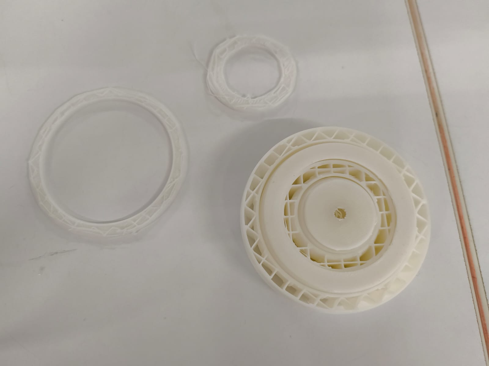
Fidget Spinner
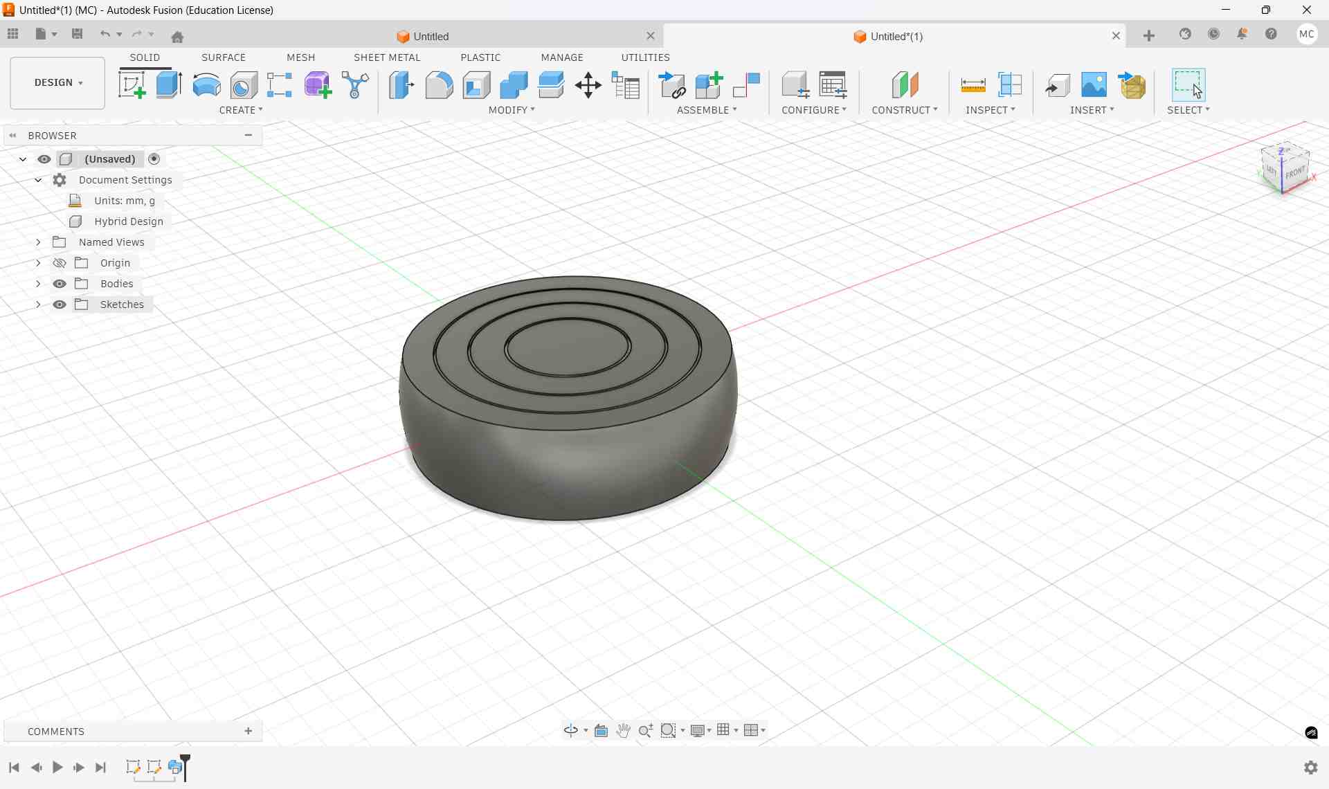
For Week 5, I designed and 3D printed a print-in-place fidget ring mechanism using Autodesk Fusion 360. The goal was to create an object that cannot be manufactured subtractively and prints as a single piece, yet retains moving parts. This project demonstrates the power of additive manufacturing in creating complex, interlocking geometries that would be impossible or impractical to fabricate using traditional subtractive methods.
This video taught me everything I know :)
Project Overview
At first glance, the model looks like four simple cylindrical rings. However, the rings are nested and mechanically free to rotate inside one another, creating a functional mechanism that spins and moves after printing.
Key Characteristics
- ✓ Prints in one complete piece
- ✓ Requires no assembly
- ✓ Spins freely after printing (no post-processing)
- ✓ Uses precision-engineered tolerance clearance
This makes it a perfect example of additive manufacturing advantage, creating complex moving mechanisms that would be labor-intensive or impossible to produce subtractively.
Design Concept
Print-in-Place Mechanism
A design where moving parts are fabricated already assembled during the printing process; No disassembly, no additional manufacturing, complete functionality from the printer.
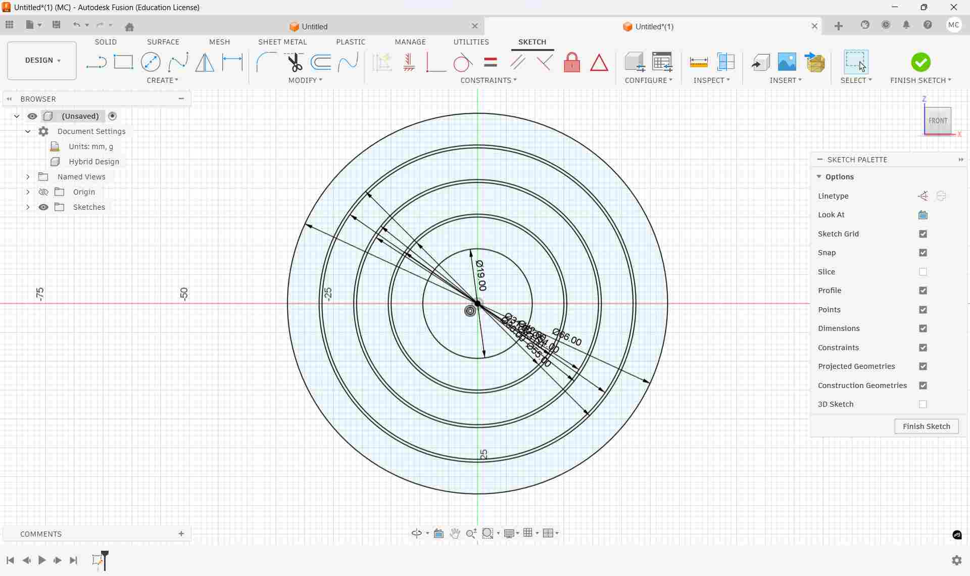
Dimension Strategy & Ring Logic
All rings are created using concentric circles from the origin, ensuring perfect alignment and rotational freedom. This geometric approach guarantees that each ring rotates around a common center point.
Circle Diameters Used (in ascending order):
Yellow = Ring inner/outer radii ::: Blue = Clearance gap circles
Step-by-Step Modeling Process
Step 1 – Create Base Sketch
- Open Front View
- Press C (Circle tool)
- Draw all circles from the origin
- Create the eight concentric circles using the dimensions above
Step 2 – Create Center Rectangle
- Press R
- Choose Center Rectangle
- Width: 66 mm
- Height: 19 mm
- Finish Sketch
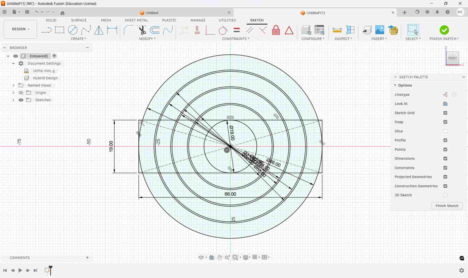
This rectangle becomes the sweep profile that defines ring thickness.
Step 3 – Create Sweep Path
- Rotate to Top View
- Start a new sketch on the top plane
- Draw one circle (Diameter: 19 mm)
- Finish Sketch

This circle acts as the sweep path.
Step 4 – Sweep Operation
- Switch to Isometric View
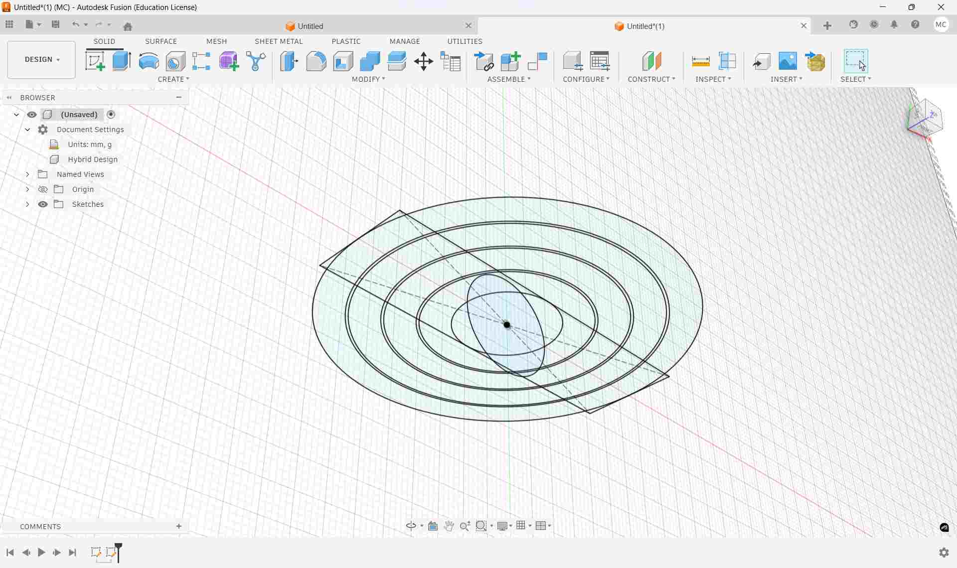
- Go to Create → Sweep
- Hold Ctrl and select all four ring profiles
- Select the 19 mm circle as the Path
- Click OK
The four nested rings are now generated.
Why the Sweep Tool Works for This Design
The Power of Parametric Sweeping
Traditional 3D modeling would require manually creating four separate torus geometries and nesting them. The Sweep tool accomplishes this in a single operation:
- Takes a 2D profile: The rectangular profile we created in Step 2
- Wraps it along a circular path: Following the 19 mm circle we defined in the top view
- Generates torus-like ring geometry: With complete dimensional control and precision tolerances
Conceptually, the sweep operation bends a straight rectangular profile into a complete circular ring shape. This parametric approach is not only computationally efficient but also allows easy modification—adjusting any dimension automatically updates all swept rings.
3D Printing Parameters & Configuration
| Parameter | Value | Reason |
|---|---|---|
| Material | PLA | Easy to print, good dimensional accuracy, ideal for precision tolerances |
| Layer Height | 0.2 mm | Balances print speed with dimensional precision and surface quality |
| Supports | None | Flat orientation eliminates support structures, reducing post-processing |
| Orientation | Flat on build plate | Maximizes bed adhesion and ensures uniform layer deposition |
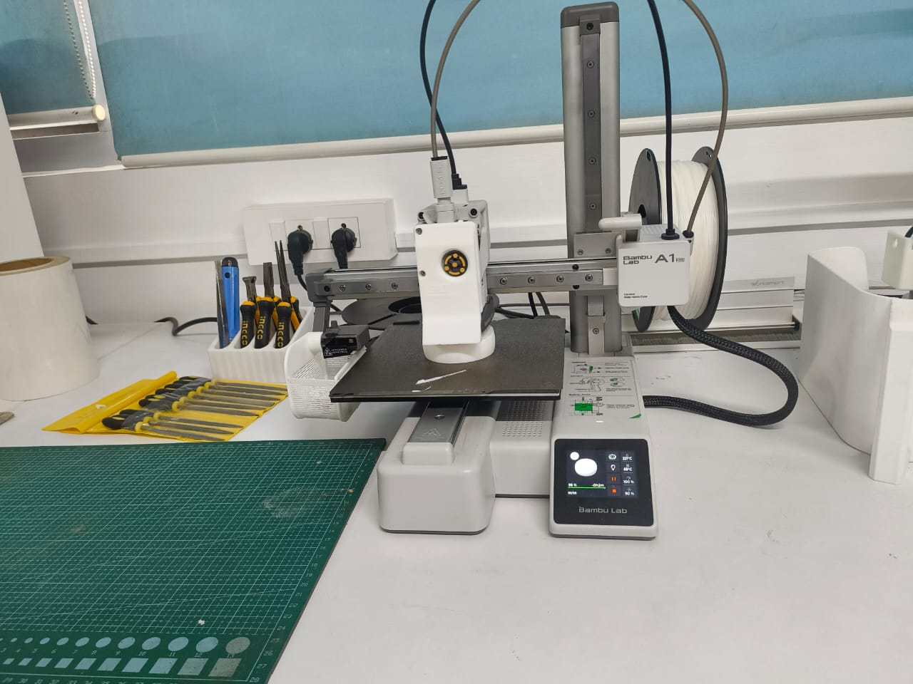
3D Printing Process – Bambu Lab A1 Mini
After completing the design of the Movable Fidget Ring in Fusion 360, I exported the model as an STL file and imported it into Bambu Studio for slicing and print preparation. The slicing process converts the 3D model into layer-by-layer instructions that the 3D printer can execute.
Printer Configuration
| Setting | Value | Purpose |
|---|---|---|
| Printer Model | Bambu Lab A1 Mini | Compact high-precision FDM printer |
| Nozzle Diameter | 0.4 mm | Standard precision nozzle |
| Material | PLA (Polylactic Acid) | Biodegradable, precise, beginner-friendly |
| Layer Height | 0.2 mm | Balance between speed and print quality |
| Support Structure | None | Flat orientation eliminates support need |
| Print Orientation | Flat on build plate | Maximum bed adhesion and stability |
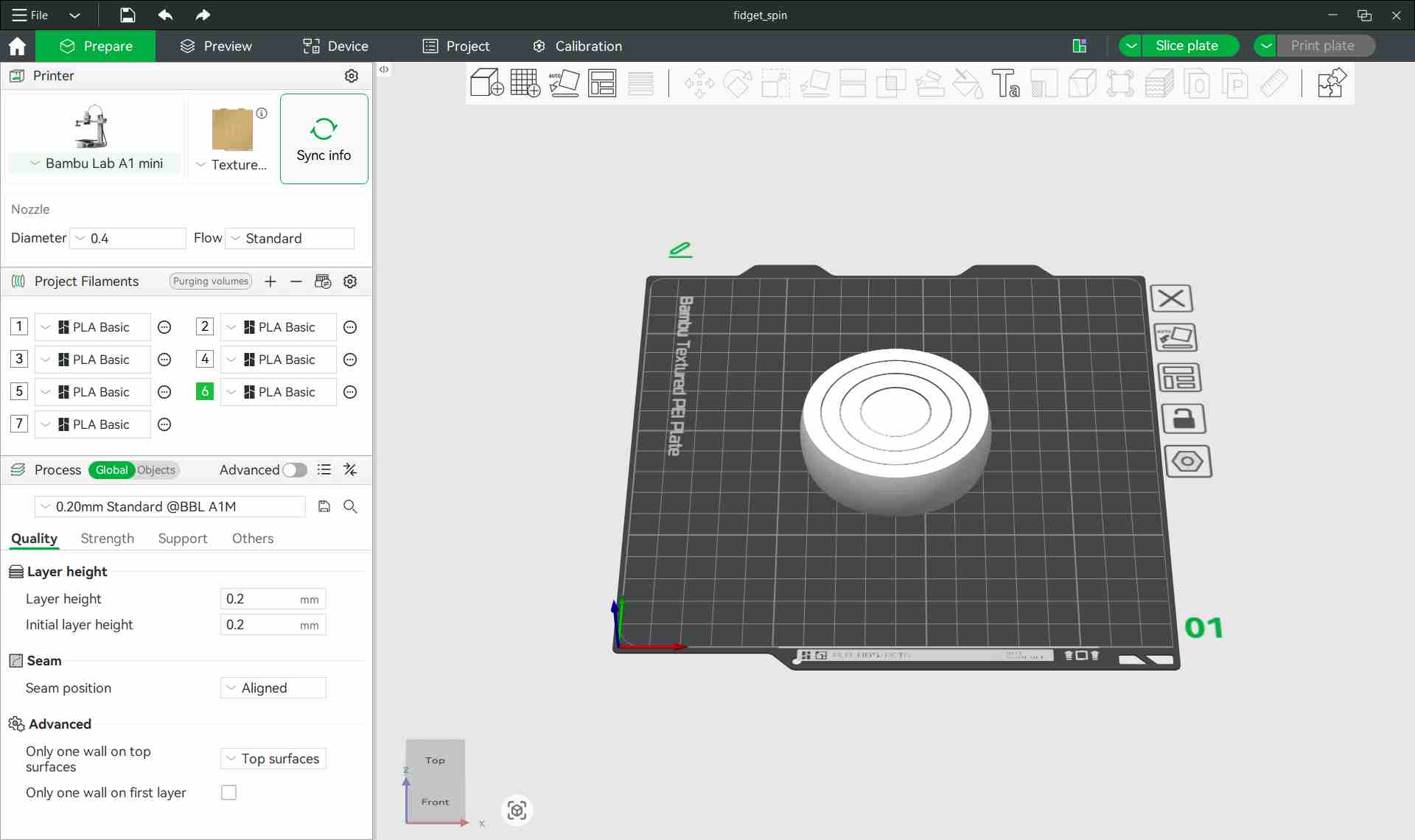
Bambu Studio slicing software displaying the complete fidget ring model ready for printing.
Pre-Print Verification & Slicing Process
After slicing the model in Bambu Studio and verifying the layer preview, I conducted thorough checks before sending the file to the printer.
Critical Pre-Print Checks:
- Generate Toolpath: Clicked Slice Plate to generate the complete layer-by-layer toolpath.
- Verify Layer Preview: Reviewed the layer preview to inspect:
- ✓ Clearance gaps between rings (must be visible in preview)
- ✓ Wall generation consistency across all layers
- ✓ Travel moves (printer head movement without printing)
- ✓ Estimated print time (~1 hour) and filament usage
- ✓ No unexpected supports or artifacts
- Confirm Settings:
- ✓ Layer height: 0.2 mm
- ✓ Material: PLA
- ✓ Nozzle diameter: 0.4 mm
- ✓ No scaling applied to model
- Send to Printer: Clicked Print Plate to transmit the file to the Bambu Lab A1 Mini via network connection.
Heating & Print Start
Once the file was transmitted, the Bambu Lab automatically initiated the heating sequence:
- Nozzle heated to 210°C (optimal for PLA)
- Build plate preheated to 60°C (ensures adhesion)
- Bed leveling verification performed automatically
- Print commenced once all temperatures reached target
Print Execution & Observations
✓ Successful Aspects
- First layer adhered properly to the build plate
- No support structures required during printing
- All four rings printed simultaneously as a single integrated object
- Print time approximately 1 hour
⚠️ Notable Challenge
During the print, the filament spool ran out midway through the process. Since the printer does not use an automatic material system (AMS), manual filament replacement was required. This introduced an issue that will be covered in the next section.
Printing Issue Encountered: Filament Runout
During the print, an unexpected material shortage interrupted the process. What happened next became a valuable learning case study in process control and mechanical reliability.
What Happened
The Sequence of Issues:
- The filament ran out during printing at approximately 98% completion
- The printer paused automatically and displayed a "Filament Runout" alert
- Manual filament insertion was performed (no automated material system available)
- Critical mistake: The filament was not fully pushed into the hotend to establish extrusion
- Printing resumed prematurely before proper material flow was verified
Timeline of Events
| Event | Description | Consequence |
|---|---|---|
| 1. Filament Depletion | The filament spool ran out during printing (~98% complete) | Print paused; printer prompted for filament reload |
| 2. Manual Reload | Manual filament insertion began (AMS not available on this printer) | Operator responsibility to feed filament properly |
| 3. Incomplete Loading | New filament was loaded but not fully pushed into the hotend | Printing resumed before proper extrusion established |
| 4. Under-Extrusion | Insufficient material flow during several layers | Visible horizontal gap; structural weakness created |
The Problem: Under-Extrusion & Layer Discontinuity
Because the filament was not completely fed into the extruder and melted properly, there was a brief but critical period where little to no material was deposited on the build plate.
Immediate Consequences
- Visible horizontal gap: A clear line visible between layers where material was missing
- Structural weakness: Layer-to-layer adhesion was significantly compromised at that height
- Surface inconsistency: Minor visual defect in the printed object
- Mechanical vulnerability: Created a stress concentration point for impact forces
Technical Classification:
Prevention Strategies for Future Prints
✓ Before Printing
- Weigh and measure filament spool before starting
- Calculate estimated filament usage
- Verify sufficient material for entire job (with 10% margin)
- Have backup filament ready during long prints
✓ During Filament Reload
- Push filament firmly until resistance is felt
- Confirm melted filament extrudes cleanly from nozzle
- Use printer's "extrude" function to purge old/cold plastic
- Wait for consistent flow before resuming print
System-Level Improvements
- Use Automatic Material System (AMS): If available, the AMS automatically switches filament without interrupting prints
- Active Monitoring: Watch print progress during critical sections or long prints
- Set Filament Runout Alerts: Some printers can alert or pause before completely depleting spool
After successfully printing the fidget ring, I conducted functional testing. Initially, everything appeared perfect, but the structural weakness created during printing would soon reveal itself catastrophically.
Initial Testing (Success)
✓ Immediate Post-Print Verification:
- All four rings rotated freely independently
- Print-in-place mechanism worked as designed
- No visible grinding or binding
- Surface finish acceptable despite the layer defect
Active 3D printing of the fidget ring showing the nested rings being printed simultaneously.
Printing the Fidget Spinner
The completed fidget ring
The Failure Event
⚠️ The Critical Moment:
During normal handling and testing, the fidget ring was accidentally dropped multiple times from a height of approximately 1-1.5 meters onto a hard floor. The impact stress exposed the invisible structural weakness that had been created during the filament runout incident.
What the Failure Revealed:
- Complete delamination: A full section separated cleanly from the main assembly
- Precise predictability: The fracture occurred exactly at the layer where under-extrusion had occurred during filament reload
- Classic failure signature: Clean, crisp break—textbook layer delamination along the Z-axis
Future Improvements & Design Considerations
| Improvement Strategy | Action | Expected Impact |
|---|---|---|
| Material Prep | Ensure sufficient filament before starting Have backup spool ready |
Eliminate mid-print filament runouts |
| Process Control | Fully purge filament before resuming after reload Verify extrusion before continuing print |
Prevent under-extrusion defects |
| Design Robustness | Increase wall thickness for critical sections Add reinforcement ribs |
Improve impact resistance |
| Verification | Inspect layer preview before printing Look for anomalies in slice preview |
Catch potential issues early |
BambuLab A1
Reprinting the Model
After analyzing the mechanical failure caused by the mid-print filament runout, I decided to print the fidget ring again to obtain a structurally sound model.
Printer and Material
- Printer: Bambu Lab A1
- Material: PLA
- Filament Color: Black
- Layer Height: 0.2 mm
- Nozzle Diameter: 0.4 mm
- Supports: None
Precautions Taken During Second Print
- Verified that sufficient filament was available before starting the print.
- Ensured the filament was properly loaded and extruding consistently.
- Observed the first few layers carefully to confirm proper adhesion.
- Monitored the print periodically to avoid interruptions.
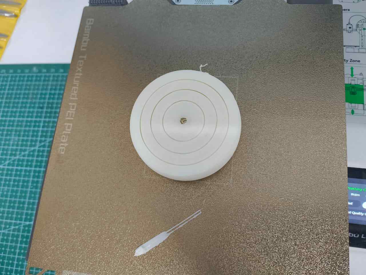
Result
The second print completed without interruption. All layers were deposited consistently, and no visible gaps were observed.
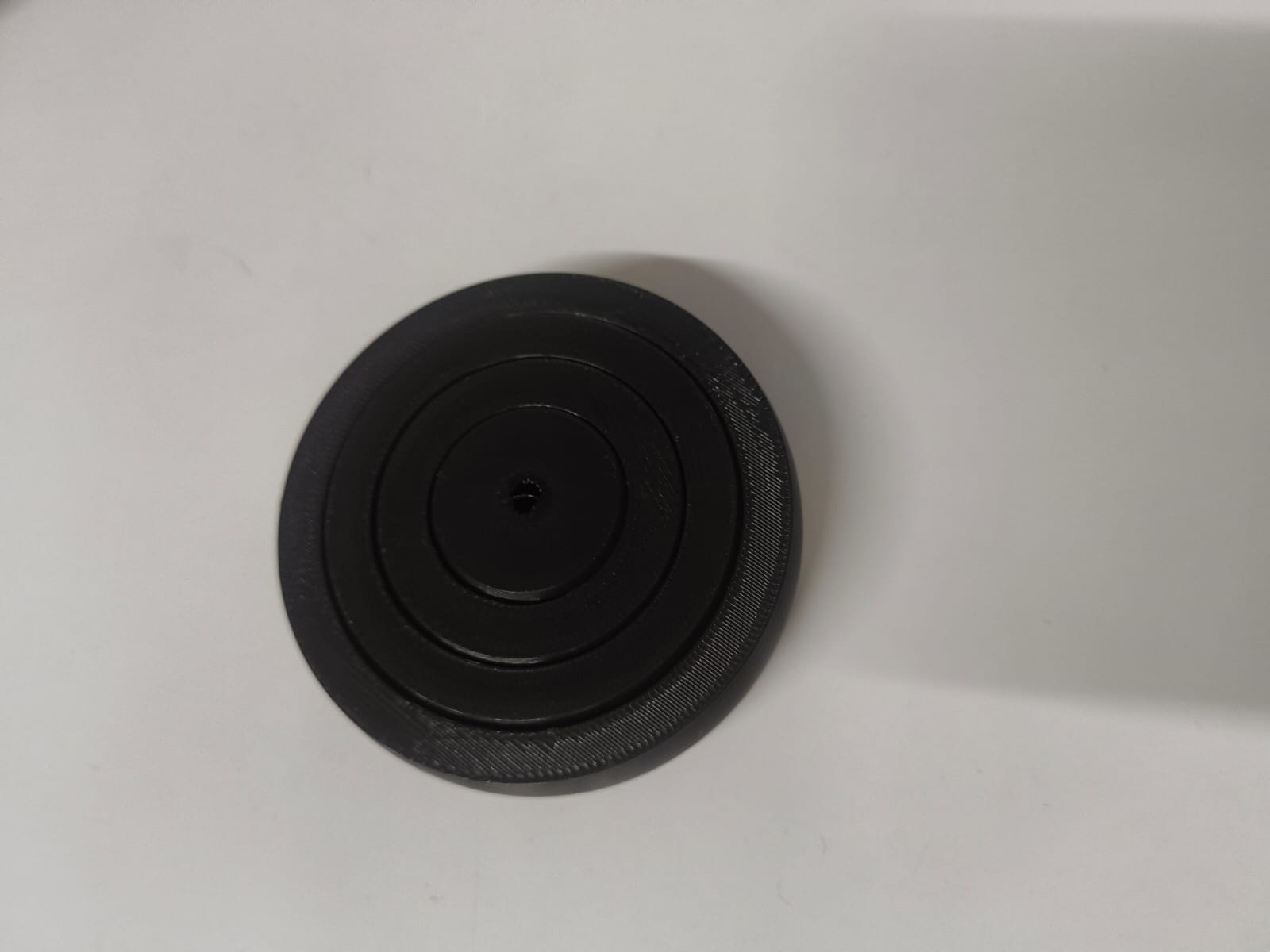
After removal from the build plate, the nested rings rotated smoothly, demonstrating proper clearance and layer bonding.
Observation
The black PLA provided better visual contrast between the rings, making the geometry and surface finish more clearly visible. The structural integrity of the reprinted model was significantly improved compared to the first attempt.
The final printed outer diameter measured 65.25 mm, while the intended design dimension was 66 mm.
This results in a dimensional difference of 0.75 mm, meaning the printed part is slightly undersized compared to the original model.
This project demonstrates an object that cannot be manufactured subtractively as a single integrated unit. The internal nested rings are mechanically free to rotate, they would require separate fabrication and careful assembly using traditional subtractive methods. Additive manufacturing allows all parts to be fabricated simultaneously in one print, eliminating assembly and achieving print-in-place functionality impossible with other fabrication methods.
3D Scanning
Software Used
- Artec Studio 15 Professional
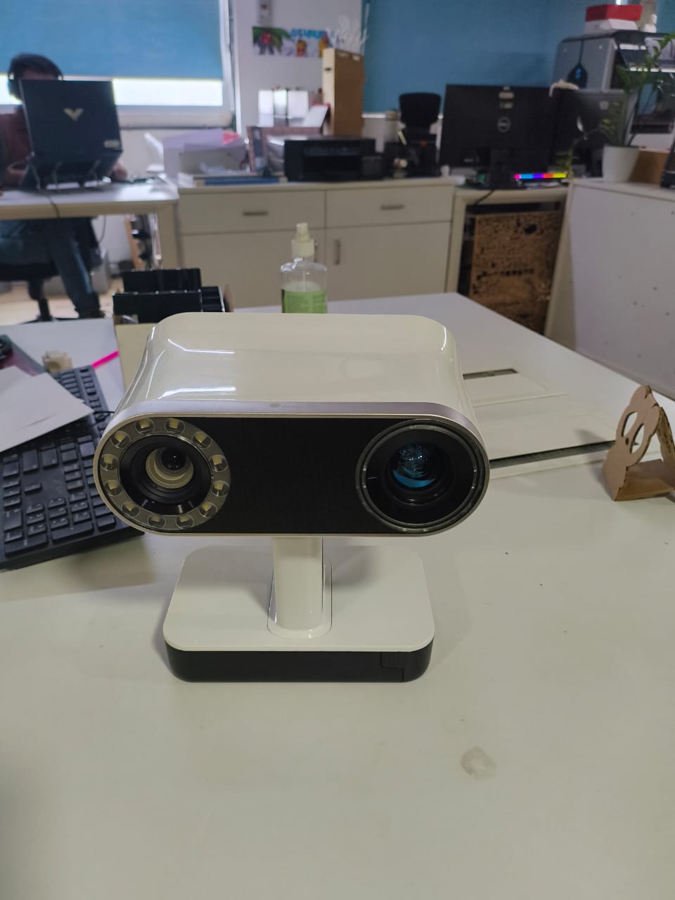
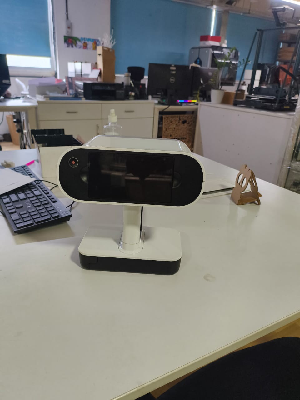
- Scanner: Artec Leo
Equipment Used
3D Scanner
Artec Leo (handheld professional 3D scanner)
The Artec Leo is a wireless handheld 3D scanner with a built-in screen and onboard processing. It captures geometry and texture in real time without requiring external markers in many cases.
Software
Artec Studio
Artec Studio is used for:
- Capturing scan data
- Aligning multiple scans
- Processing point clouds
- Generating meshes
- Exporting final STL/OBJ files
3D Scanning Process - Stool
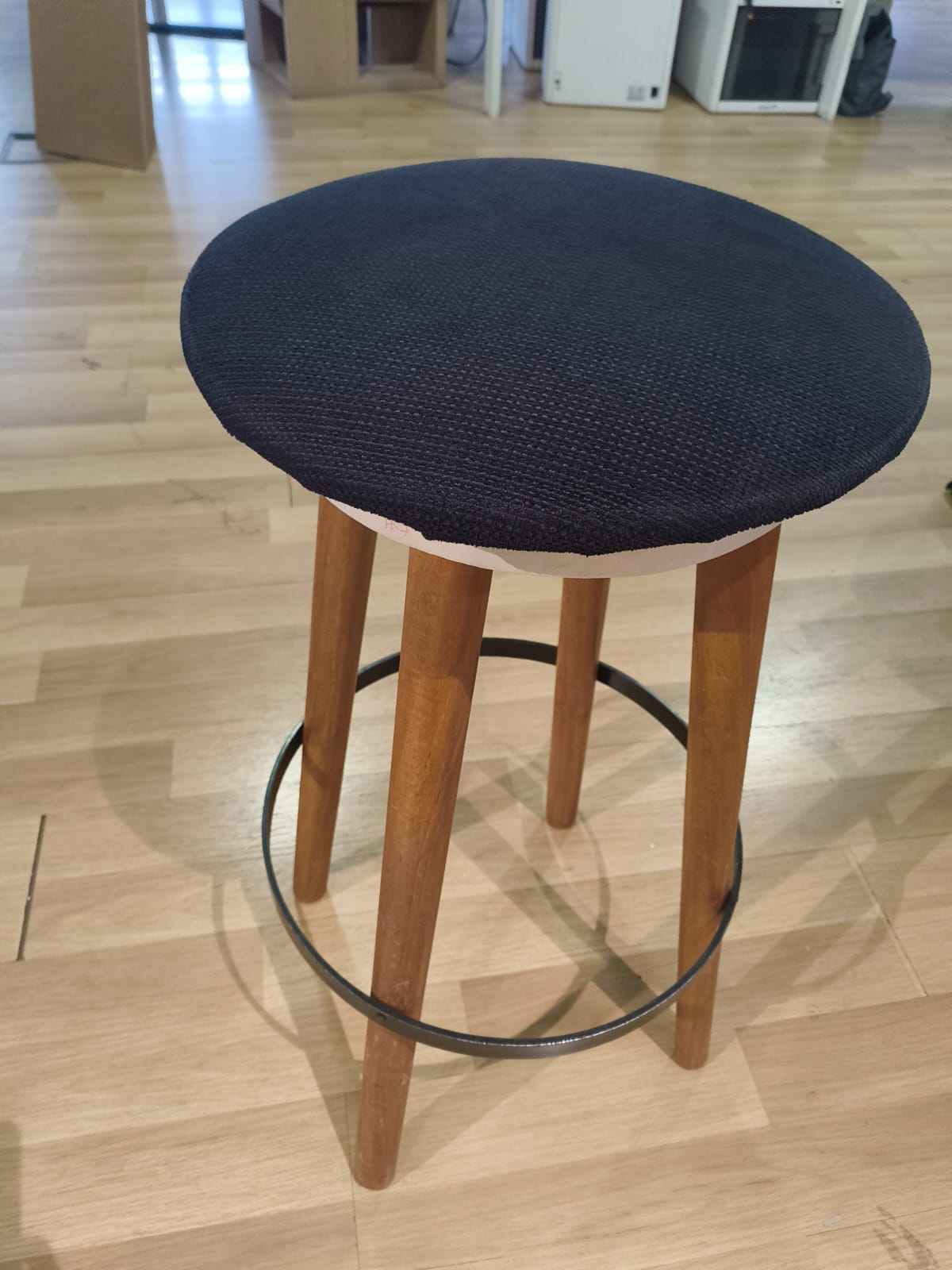
Object Selection
For the 3D scanning assignment, I selected a wooden stool available in the Fab Lab. The stool was chosen because it has a combination of flat surfaces and cylindrical legs, making it suitable for testing the scanner's ability to capture both curved and planar geometries. Additionally, its moderate size and stable structure made it convenient to scan from multiple angles.
Preparation Before Scanning
Before starting the scan:
- The stool was placed on the floor in an open space.
- The surrounding area was cleared to reduce unwanted geometry capture.
- Normal indoor lighting was maintained.
- The stool surface was inspected to ensure it was not reflective.
Starting the Scan - Settings
- The Artec Leo scanner was powered on.
- The Scan button was pressed on the device screen.
- A new scan project was created on the Artec Leo.
- Scan mode: Object mode
- Resolution: Ultra
- Texture capture: Enabled
- The scanner was positioned at a stable working distance from the stool.
Capturing the Geometry
- The scanner was moved slowly around the stool.
- Multiple passes were taken to ensure full surface coverage.
- The top surface, legs, and side areas were scanned carefully.
- Additional attention was given to the cylindrical legs to avoid tracking loss.
- The real-time preview on the scanner display was used to monitor coverage.
Completing the Scan
- Scanning was stopped once the stool was fully captured.
- The scan project was saved inside the Artec Leo.
- The captured data was stored as a single scan session representing the complete geometry of the stool.
Observations During Scanning
- Slow and steady movement maintained stable tracking.
- The natural wooden texture helped the scanner maintain alignment.
- The floor surface was unintentionally captured along with the stool.
- Thin cylindrical legs required careful movement for accurate capture.
Connecting the Scanner and Importing the Project
The following steps were performed to begin the 3D scanning process:
Step 1 – Open Artec Studio
Artec Studio 15 Professional was launched on the computer.
Step 2 – Import Leo Project
From the top menu:
File → Import
Selected: Leo Project
This option allows importing data directly from the Artec Leo scanner.
Step 3 – Connect to Scanner
After selecting Leo Project:
- Clicked Connect to Scanner
- The software searched for available Artec Leo devices
- Selected the connected scanner
Step 4 – Proceed
Once the scanner was detected:
- Clicked Proceed
- The system established communication between the scanner and Artec Studio
Step 5 – Select Project
After connection:
- The list of available scan projects stored inside the Artec Leo was displayed
- Selected the required project
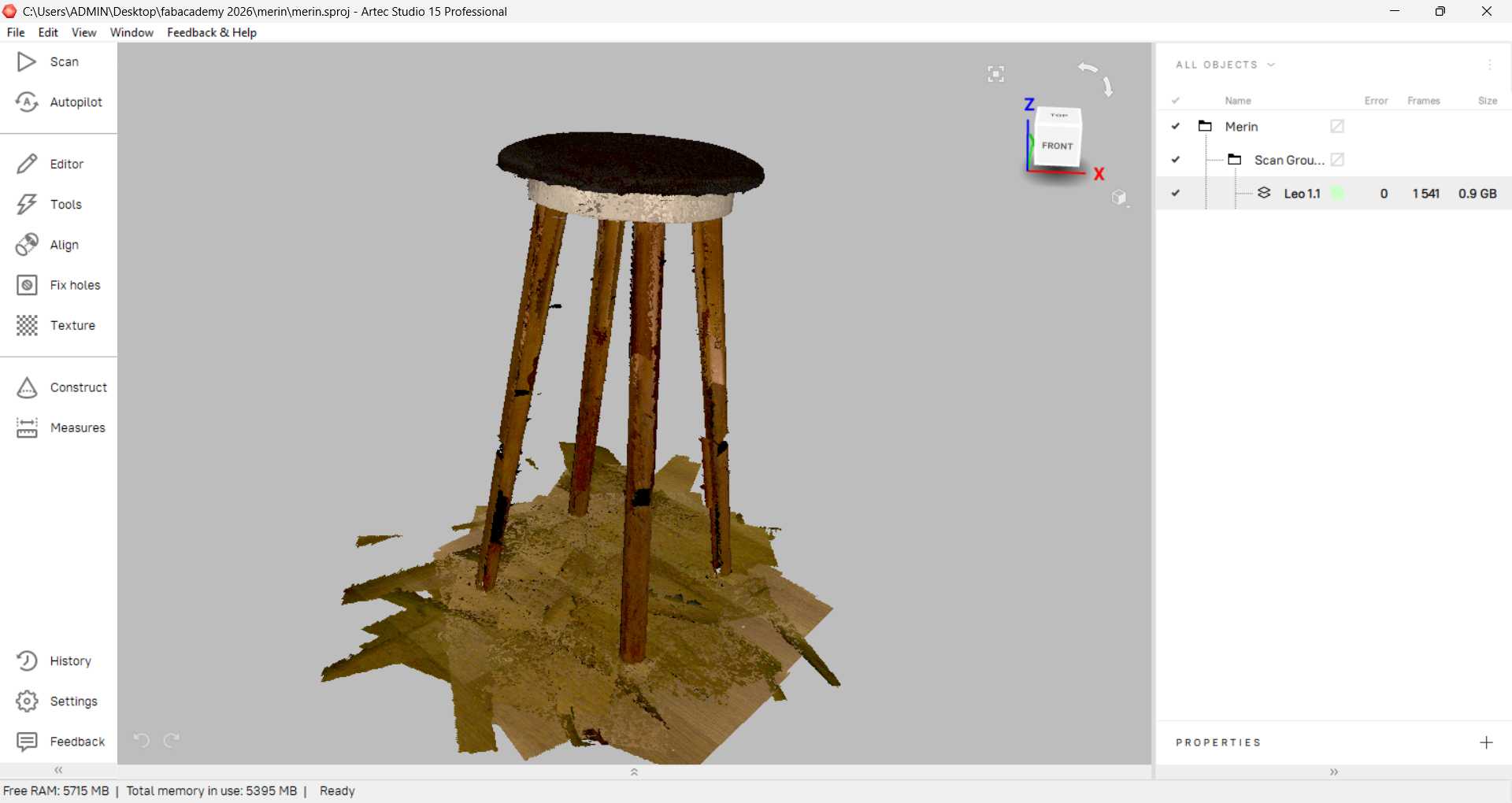
Step 6 – Import
Clicked Import
- The scan data was transferred from the Artec Leo to Artec Studio
- The scan appeared inside the workspace under Scan Group
- The imported project contained multiple frames captured during scanning
Connection Method and File Transfer
Initially, the scanner was connected to the computer using wired connection (Ethernet cable). However, this method caused noticeable time delay during data transfer and communication between the Artec Leo and Artec Studio.
Due to the delay and slow file transfer speed, the connection method was changed.
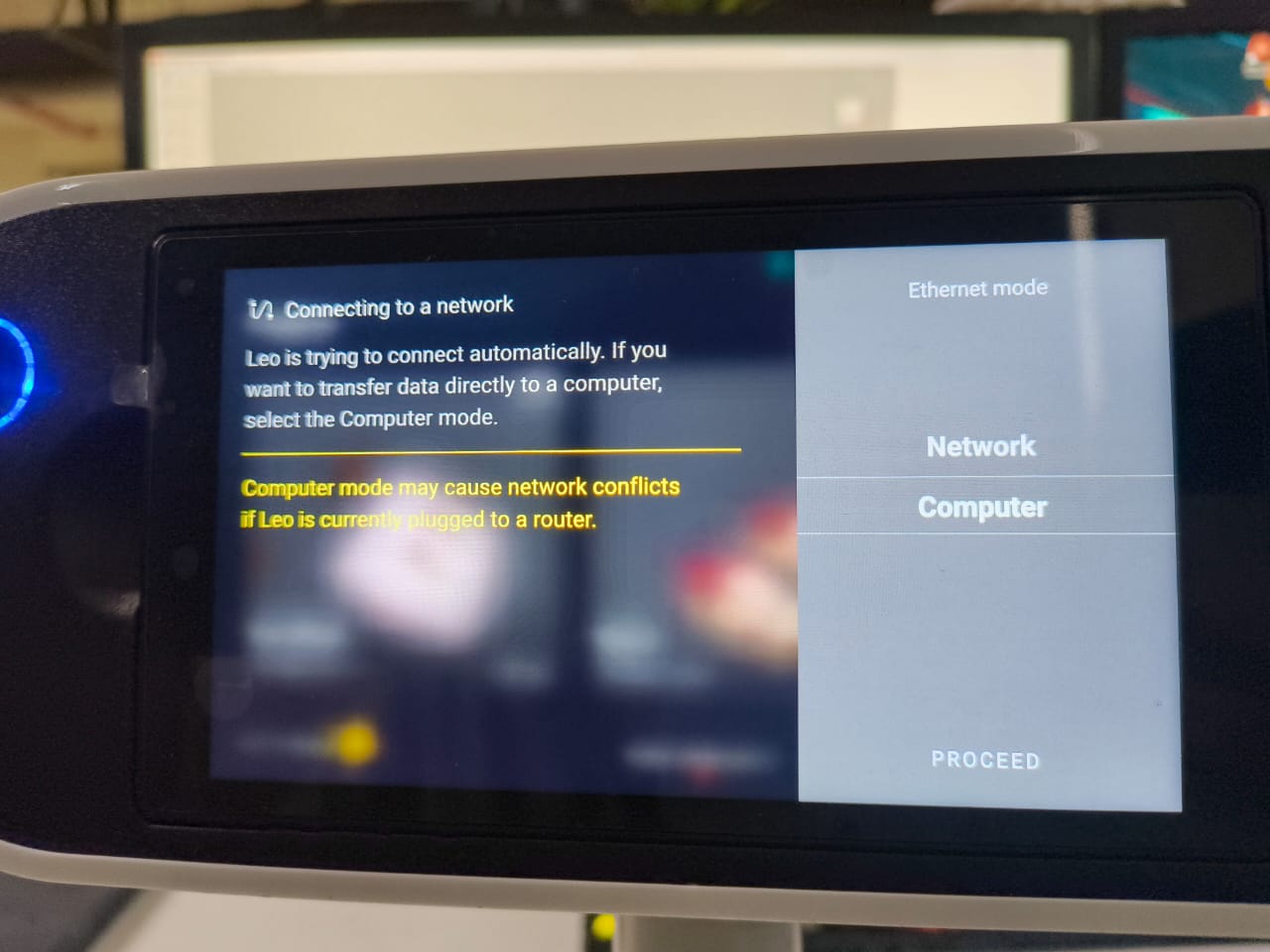
Switching to Network Mode
The scanner was switched to Network Mode instead of direct wired computer mode.
Steps followed:
- Powered on the Artec Leo scanner
- Selected Network Mode on the scanner screen
- Connected the scanner to the same network as the computer
- Opened Artec Studio
- Selected:
File → Import → Leo Project - Clicked Connect to Scanner
- Clicked Proceed
- Selected the required project
- Clicked Import
Using Network Mode significantly improved the file transfer process. The scan data was transferred smoothly from the scanner to Artec Studio without noticeable lag.
Processing in Artec Studio
Once the scan was imported into Artec Studio, the following processing steps were performed to generate the final 3D model.
1. Base Removal
During scanning, part of the floor surface beneath the stool was also captured. This unwanted geometry was removed before further processing.
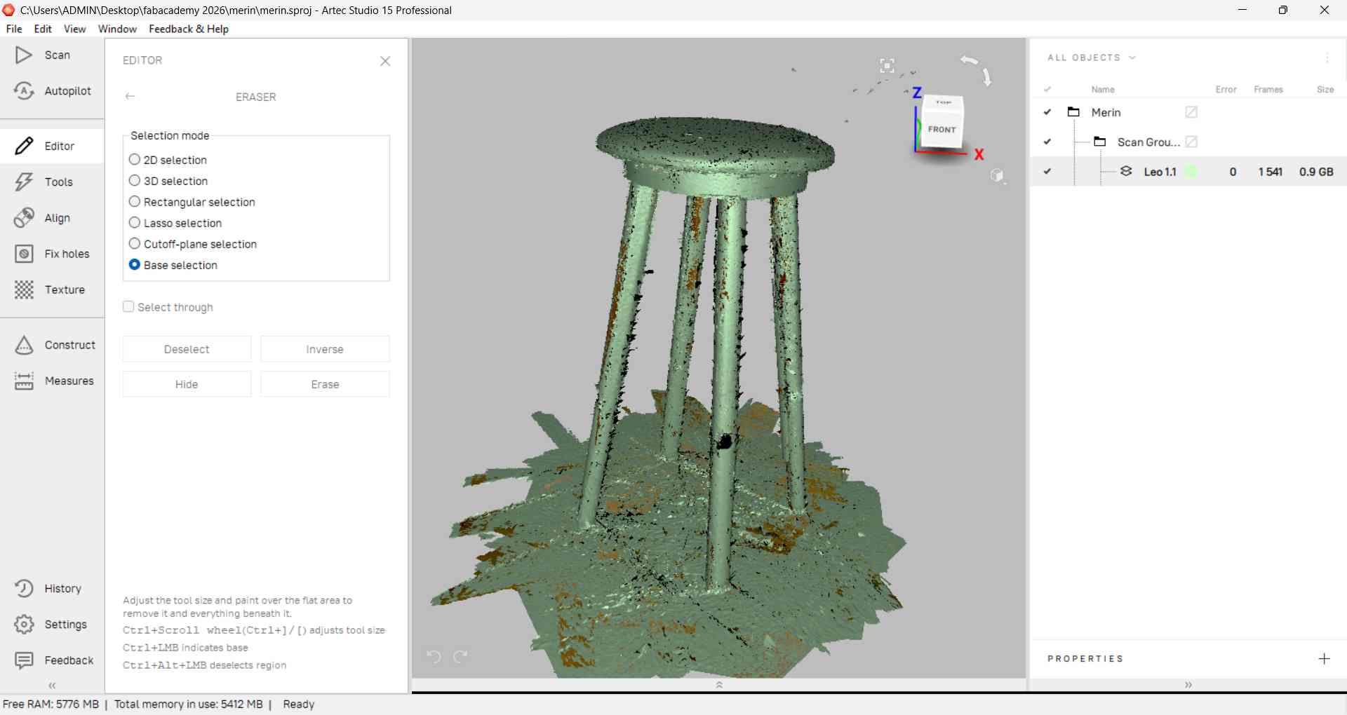
Steps performed:
- Selected the scan in the workspace
- Opened the Eraser tool
- Used Base Selection to automatically detect the flat floor surface
- Deleted the selected base region
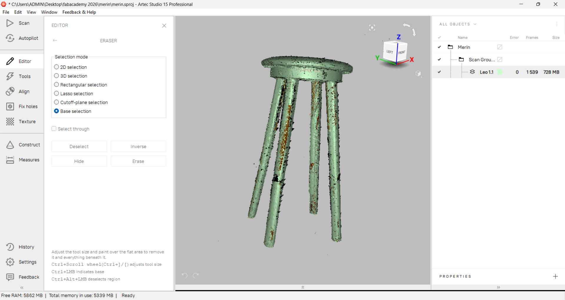
This ensured that only the stool geometry remained for further processing.
2. Global Registration
Global Registration was applied to refine the scan data and improve overall accuracy.
This step helped to:
- Reduce minor deviations
- Improve data consistency
- Optimize the scan before mesh generation
3. Outlier Removal
After base removal and global registration, small floating fragments and unwanted noise were visible in the scan data. These were removed before mesh generation to ensure a clean final model.
Steps performed:
- Selected the scan data in the workspace
- Opened the Eraser tool
- Used rectangular or lasso selection to highlight floating fragments
- Deleted the selected unwanted regions
- Repeated the process until only the stool geometry remained
This step removed stray points and isolated fragments, resulting in a cleaner dataset for Sharp Fusion.
4. Sharp Fusion
Sharp Fusion was applied to convert the processed scan data into a high-resolution mesh.
This generated a detailed 3D surface model of the stool.
5. Hole Filling
After mesh generation, small gaps and open boundary areas were detected in the model. These were filled using the Hole Filling tool in Artec Studio.
Steps performed:
- Selected the fused mesh
- Opened the Hole Filling tool
- Allowed automatic detection of open boundaries
- Applied hole filling
- Verified surface continuity
This ensured the mesh became watertight and ready for export.
File Export
After completing the processing workflow:
- The model was exported as STL for 3D printing.
- The model was exported as OBJ when texture data was required.
Challenges Faced
- Maintaining consistent scanning distance
- Avoiding tracking loss during movement
- Cleaning small mesh noise
- Capturing undercut regions accurately
Opening the File in Bambu Studio
After exporting the processed model as an STL file from Artec Studio, the file was opened in Bambu Studio for 3D printing preparation.
Steps performed:
- Launched Bambu Studio
- Clicked Open
- Selected the exported STL file
- Imported the model into the workspace
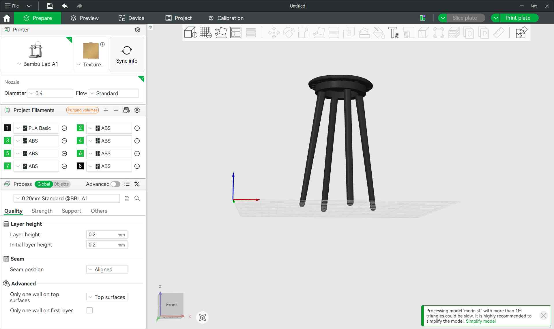
Once imported, the model appeared on the build plate and was ready for:
- Scaling (if required)
- Orientation adjustment
- Slicing preparation
This step prepared the scanned stool model for additive manufacturing.
You can download the 3D printed model's files files from here and the 3d scanned object's file from here.
3D Print Results
The scanned stool model was successfully 3D printed using a Bambu Lab FDM printer with lavender/purple PLA filament.
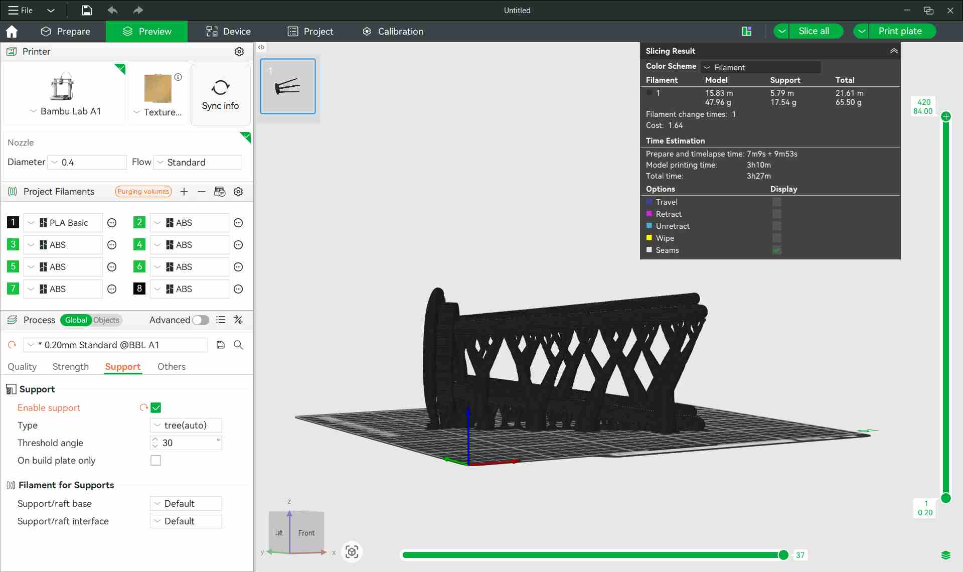
Print on the Bed (with Supports)
After slicing in Bambu Studio, supports were automatically generated beneath the seat overhang and around the three legs. The image below shows the print immediately after the job completed, still resting on the textured PEI build plate. The support structures are clearly visible running along the legs and branching out to stabilize the seat's underside.
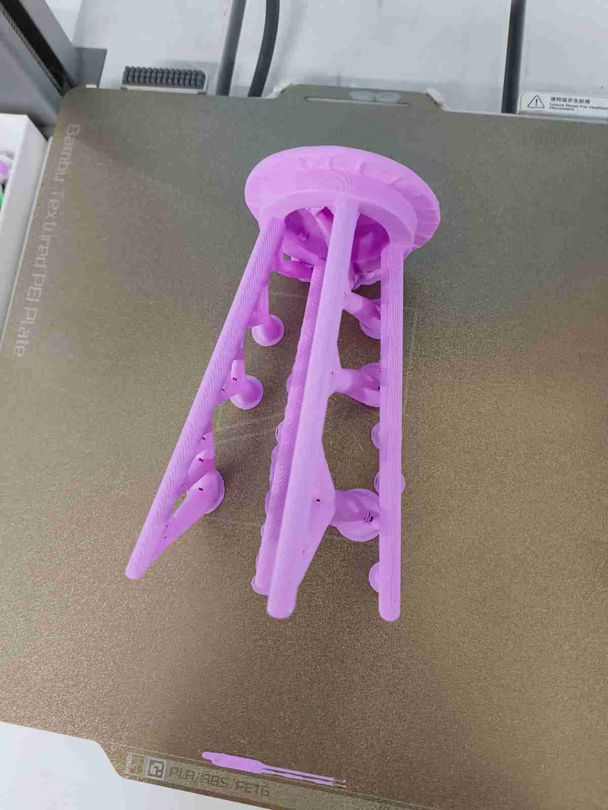
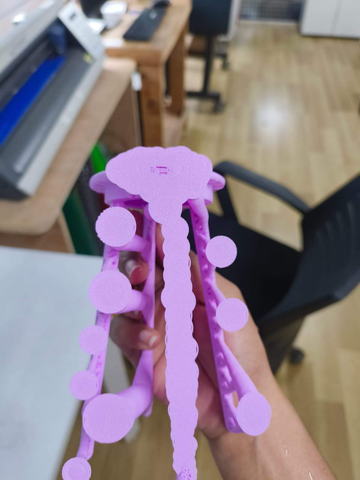
Removing Supports
Once removed from the build plate, the support material was still attached to the model. The supports created a distinctive jellyfish-like silhouette, long strands descending from the seat with rounded termination blobs at their tips. These are tree-style supports generated by Bambu Studio, which are easier to remove than traditional grid supports and leave a cleaner surface finish on the model.
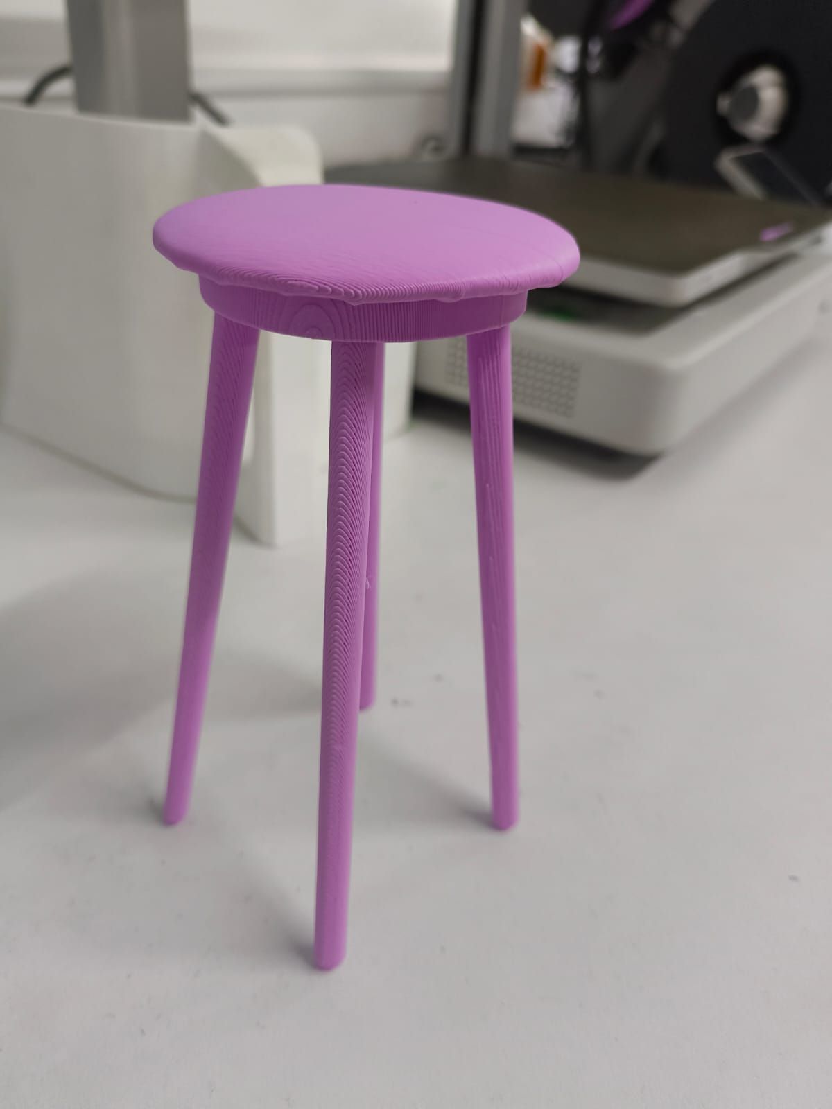
Final 3D Printed Stool
After snapping off and cleaning all support material, the final print revealed a clean miniature three-legged stool — a faithful reproduction of the originally scanned object. Key observations:
- The circular seat is flat and smooth on the top surface
- Three tapered legs splay outward slightly for stability, matching the geometry of the original scanned stool
- FDM layer lines are visible along the legs, running parallel to the print direction
- The lip/rim around the seat edge was well-reproduced, demonstrating that the 3D scan captured the fine edge detail accurately
- Print color: lavender PLA, chosen for visibility of surface detail
- Overall the scan-to-print workflow produced a dimensionally accurate and structurally sound result
You can download the Fusion file for the Fidget Spinner from here.
You can download the Fusion file for the Stool from here.