COMPUTER CONTROLLED CUTTING
Group assignment:
- Do your lab's safety training
- Characterize your lasercutter's focus, power, speed, rate, kerf, joint clearance and types.
- Document your work to the group work page and reflect on your individual page what you learned.
Individual assignments
- Design, lasercut, and document a parametric construction kit, accounting for the lasercutter kerf.
- Cut something on the vinyl cutter.
Group Assignment
Laser Cutter Characterization
Understanding Machine Parameters
As part of our group assignment, we systematically characterized the Trotec Speedy 100 laser cutter to understand how different machine parameters affect cutting performance and material behavior. This characterization is essential for designing accurate press-fit assemblies and achieving consistent, precise cuts.
Key Parameters Tested
- Power: Controls laser beam intensity and cutting depth
- Speed: Determines laser head movement rate—affects exposure time and material burn
- Frequency (Rate): Affects how laser pulses interact with the material surface
- Focus: Ensures laser beam is concentrated at correct height for clean cutting
- Kerf: The width of material removed during cutting (typically 0.1-0.2mm)
- Joint Clearance: Required spacing for press-fit assemblies to function properly
Kerf Testing & Measurement
Kerf is perhaps the most critical parameter for precision design. We performed controlled kerf tests on three materials to measure exact material loss during cutting.
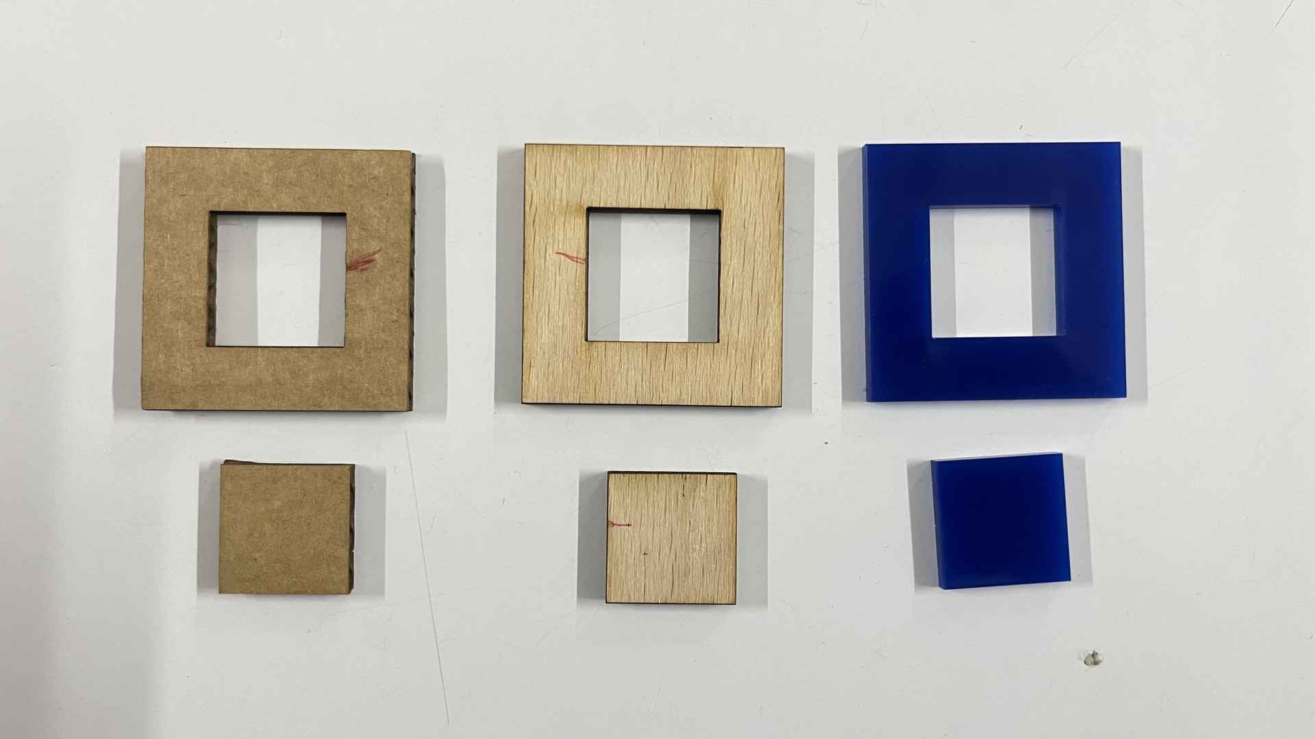
Kerf test pieces cut in cardboard, wood, and acrylic with measured slot widths to determine kerf values.
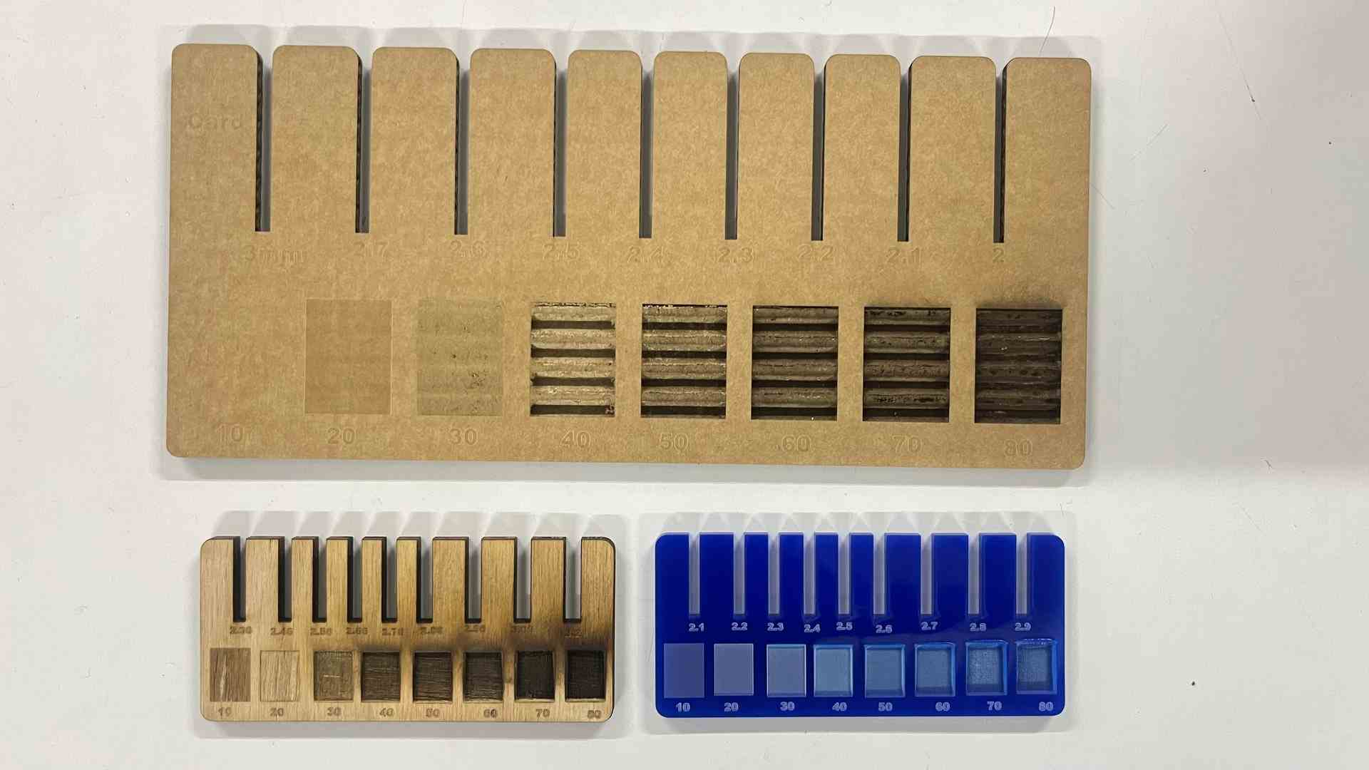
Kerf comb test pattern showing progressive slot widths for precise kerf identification in each material.
How the Kerf Was Measured
A test piece with multiple slots of known designed widths was cut in each material. The actual slot widths were then measured with digital calipers. By comparing the designed dimensions with the measured dimensions of the cut pieces, the kerf value was calculated:
Divided by 2 because the laser removes material on both sides of the cut path.
Measured Kerf Values
| Material | Thickness | Power (%) | Speed (%) | Kerf (mm) |
|---|---|---|---|---|
| Cardboard | 3 mm | 80 | 2.5 | 0.30 |
| Wood (Plywood) | 3 mm | 80 | 1 | 0.245 |
| Acrylic | 3 mm | 90 | .9 | 0.125 |
Material-Specific Observations
Cardboard — 0.30 mm
- Largest kerf due to low material density
- Consistent and predictable
- Minimal edge damage
Wood — 0.245 mm
- Slight burn marks at edges
- Kerf can vary slightly with grain direction
- Requires higher power than acrylic
Acrylic — 0.125 mm
- Smallest kerf of the three materials
- Cleanest, most predictable edge finish
- Sharp, crisp cuts
Learning Outcome
Kerf varies significantly by material type and laser settings. The effective kerf was found to be approximately 0.3 mm for cardboard, 0.245 mm for wood, and 0.125 mm for acrylic. These values must be factored in when designing parametric press-fit assemblies — subtracting the kerf from slot widths ensures parts fit correctly after cutting.
Safety Training & Critical Precautions
⚠️ Essential Safety Protocols
- Supervision: Never leave the laser cutter unattended during operation
- Ventilation: Verify exhaust airflow and air assist are active before starting
- Material Verification: Always check materials—avoid hazardous plastics (PVC, polycarbonate)
- Enclosure: Keep machine lid closed during cutting to contain fumes
- Post-Job: Allow time for fumes to clear before opening lid
- Scrap Removal: Remove cut pieces immediately to prevent ignition
- Emergency Equipment: Fire extinguisher must be within reach at all times
Warning Signs & Emergency Response
✗ Danger Signs
- Visible smoke inside chamber = improper airflow or bad parameters
- Red/orange glow = material smoldering or actively burning
- Strong acrid smell = potential hazardous gas release
✓ Response Protocol
- STOP immediately if smoke detected—do not continue cutting
- Smother fires by covering with flat board to deprive oxygen
- Use extinguisher if fire spreads beyond the material
- Evacuate if fire cannot be controlled
You can see our Group Assignment documentation here.
Individual Assignment
Vinyl Cutting
Vinyl cutters are precision machines used for creating custom decals, signs, and apparel decorations. The machine reads vector files and uses a sharp blade to cut designs into thin vinyl material. Vector designs are transmitted to the machine via USB or serial connection, and the cutting blade follows digital paths with exceptional accuracy.
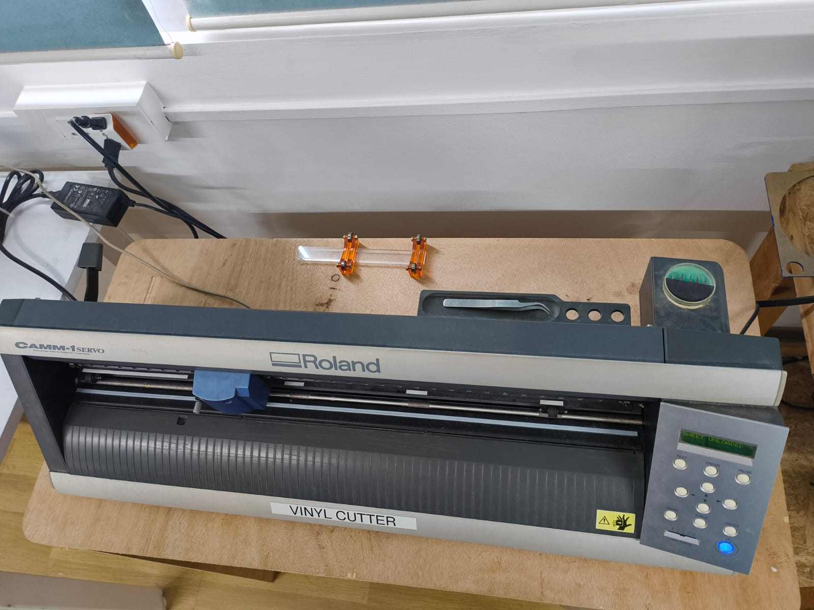
The Machine: Roland GX-24
The Roland GX-24
Unlike motorized cutting heads, the Roland GX-24 uses a passive blade cutter system. The blade is mounted in a freely swiveling holder that automatically rotates to align with the cutting direction, similar to a caster wheel on a shopping cart.
Servo Motor Features
- High positioning accuracy: Repeatable placement to ±0.1mm
- Smooth motion control: Servo motors enable precision speed modulation
- Precise corners: The blade can cut sharp, clean corners without hesitation
- Consistency: Identical results across multiple identical cuts
These capabilities make the Roland GX-24 ideal for detailed vector designs including logos, lettering, decals, complex patterns, and custom apparel decoration.
Vinyl Cutting Project
For the vinyl cutting assignment, I created a custom Groot vinyl decal from a raster image. Since vinyl cutters operate on vector paths (not pixels), the raster image required conversion to vector format before cutting.

Source raster image (JPG) from Pinterest
You can get this image from here
Why Vector Format Is Required
Raster images (JPG, PNG) are made of pixels with no path information. Vinyl cutters need vector files (SVG) that define continuous paths for the blade to follow. Vector graphics are resolution-independent and can scale to any size without quality loss.
Conversion Workflow: Raster → Vector
The image was processed using Inkscape, a free, open-source vector graphics editor, to convert the raster image into vector paths suitable for vinyl cutting.
-
Step 1: Import the Raster Image
Open the JPG file in Inkscape (File → Open). The image appears as a raster bitmap, unsuitable for vinyl cutting without conversion.
Raster image in Inkscape
-
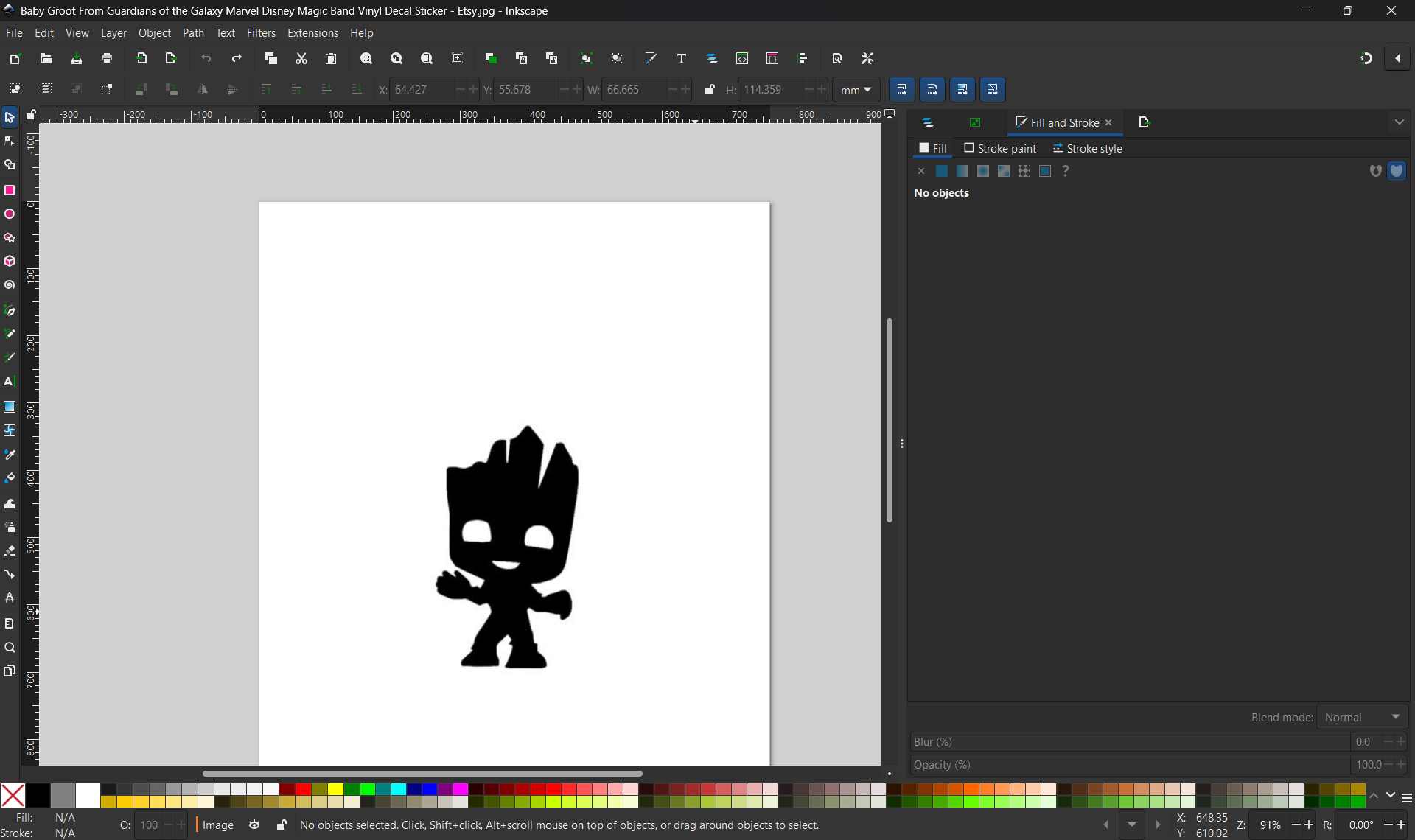
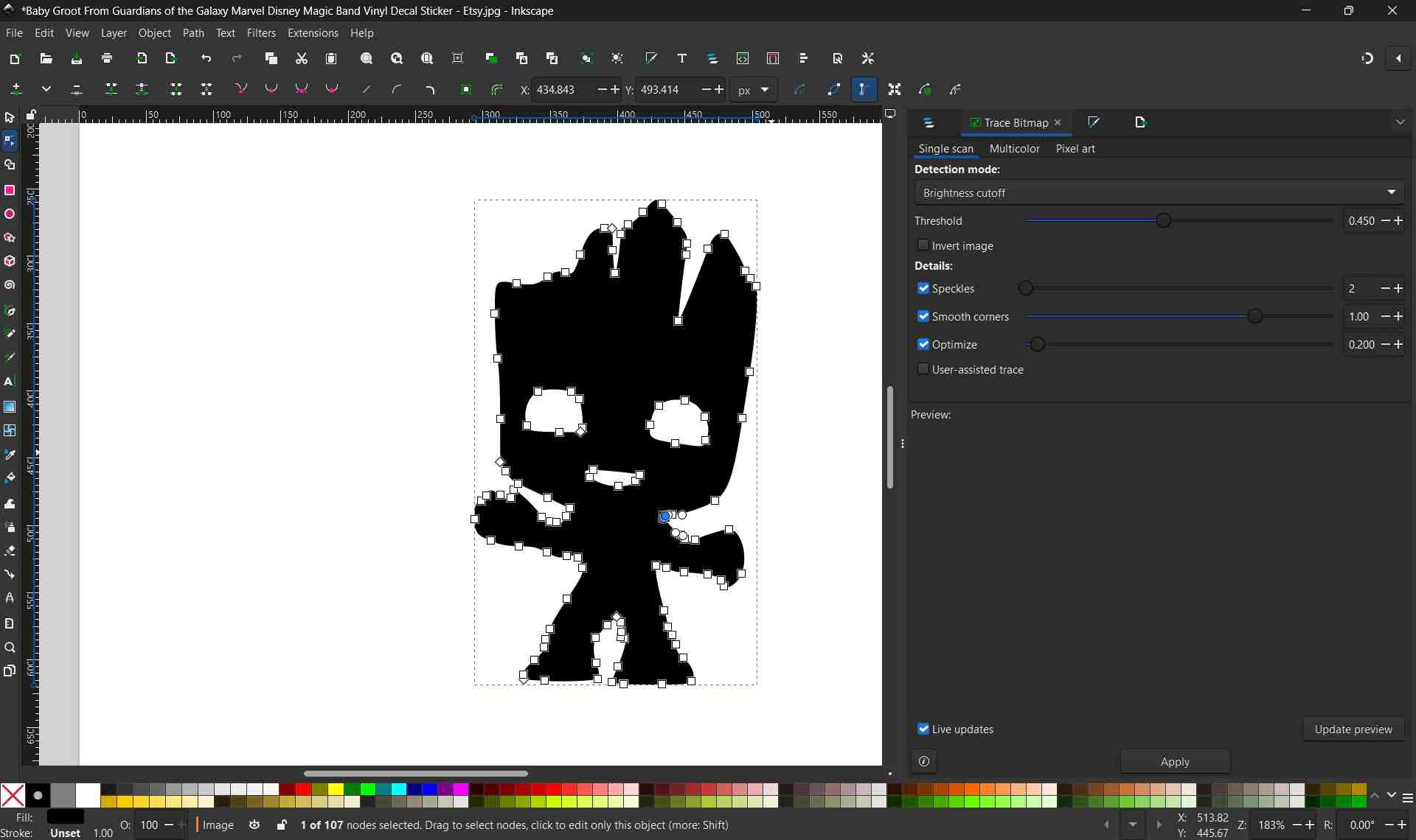
Step 2: Trace the Bitmap to Vector
Select the image and use Path → Trace Bitmap to convert pixels into vector paths. Adjust threshold values to create a solid black silhouette without internal details or noise—this ensures clean cutting.
-
Step 3: Clean and Simplify Paths
Delete the original raster image layer. Inspect the vector paths and simplify where needed. The final design should be a single continuous black silhouette ready for vinyl cutting.
Clean vector paths with visible nodes
-
Step 4: Export as SVG
Save the final vector design as SVG format (File → Export → Export As → Save as .svg). This file format is universally supported by vinyl cutter software.

Completed SVG vector file
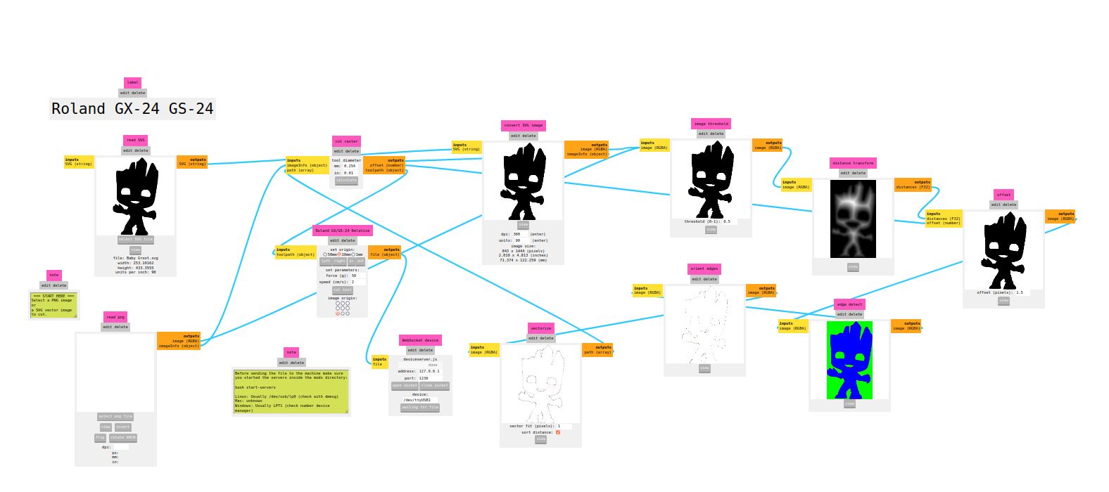
Generating Cutting G-code with Fab Modules
After creating the SVG file, I used Fab Modules (modsproject.org), a browser-based tool for generating machine-specific toolpaths. Fab Modules converts vector designs into G-code instructions that the vinyl cutter can execute.
Accessing Fab Modules
Visit modsproject.org in your browser. The interface displays a blank workspace initially—you navigate by right-clicking to access the main menu.

Fab Modules interface
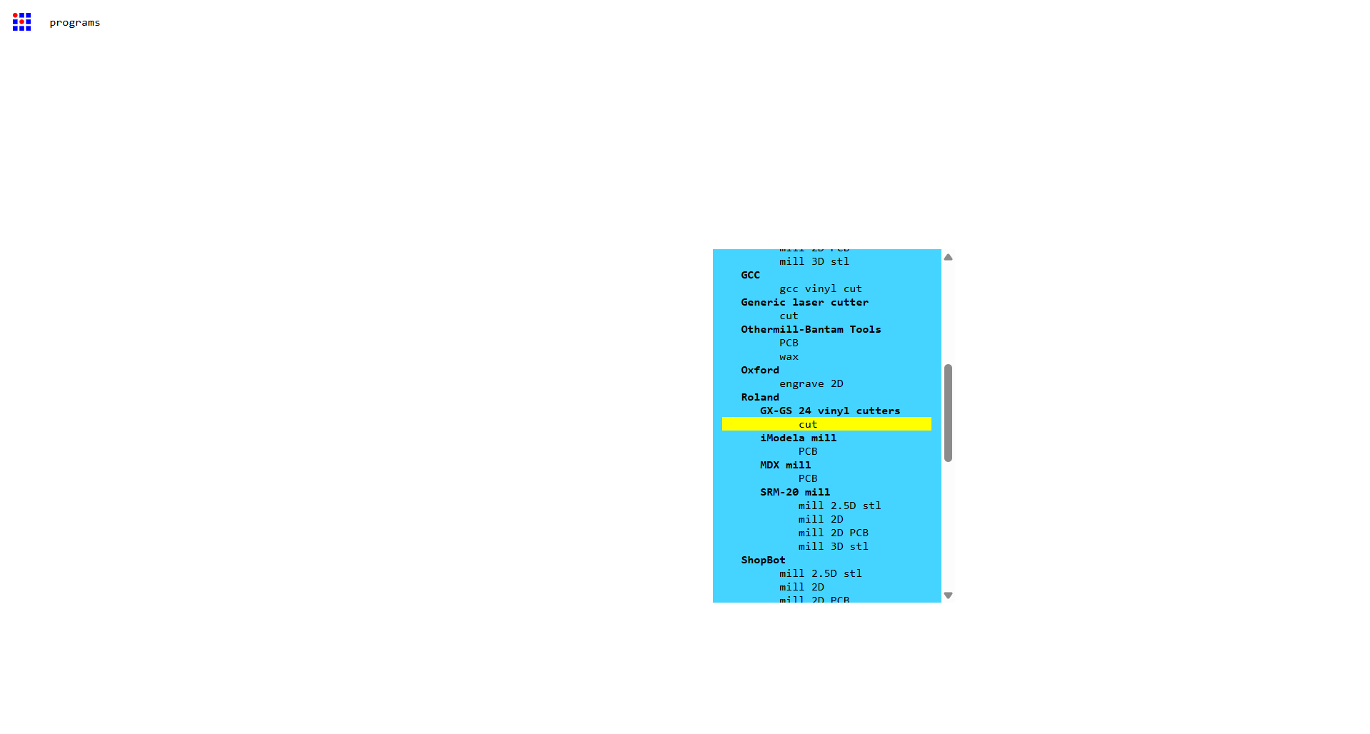
Selecting Machine & Workflow
- Right-click on the canvas and select Programs
- Select Roland GX-24 / GS-24 vinyl cutter from available machines
- Choose the Cut operation (for vinyl cutting)
This loads the predefined workflow specific to the Roland vinyl cutter, complete with input/output nodes.
Machine and operation selection in Fab Modules.
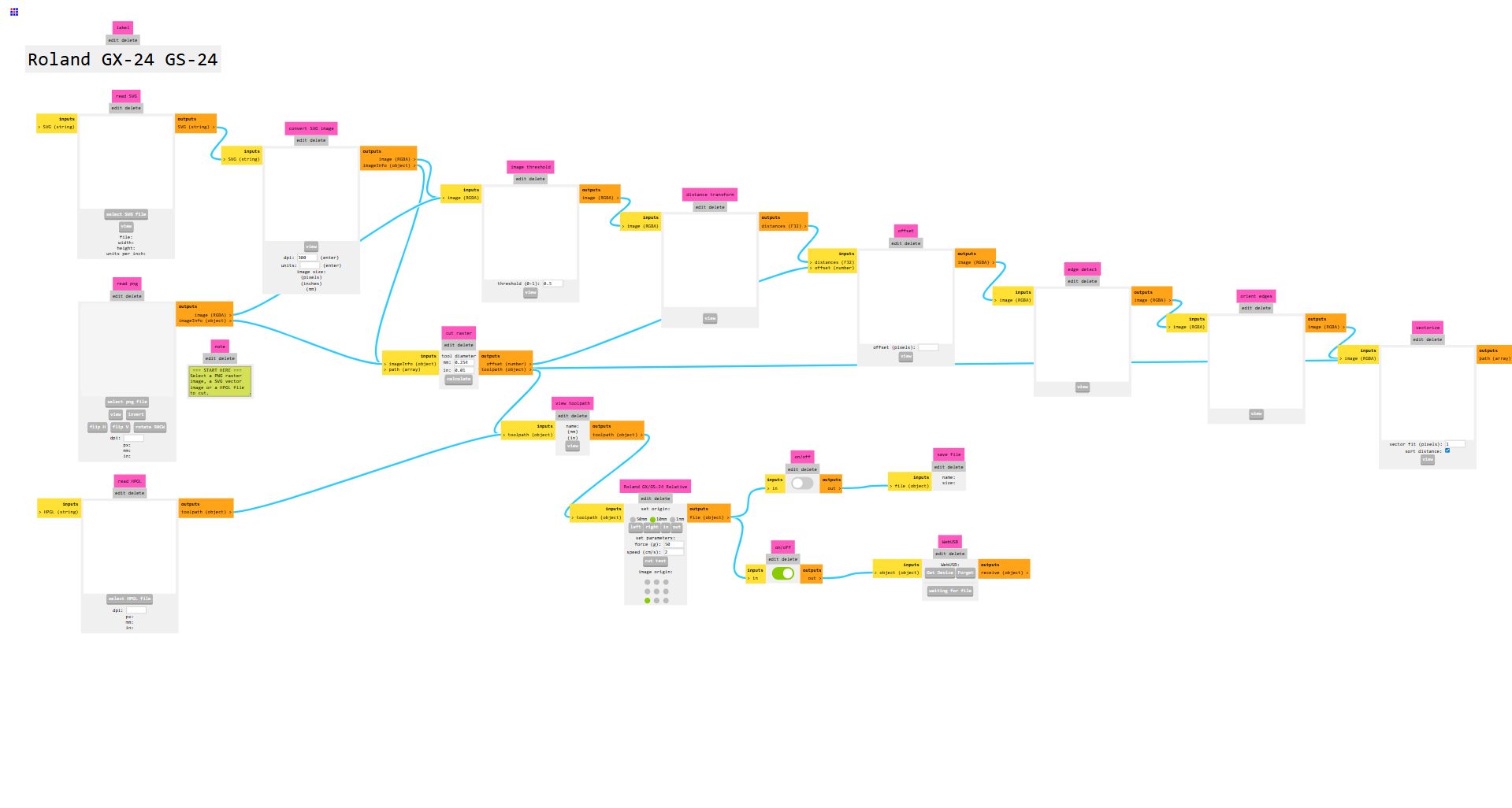
Workflow structure: SVG input → processing nodes → cutting preview → G-code output.
Importing the SVG Design
- Locate the leftmost node labeled "read svg"
- Click Select SVG file button
- Load the Groot vector file prepared in Inkscape
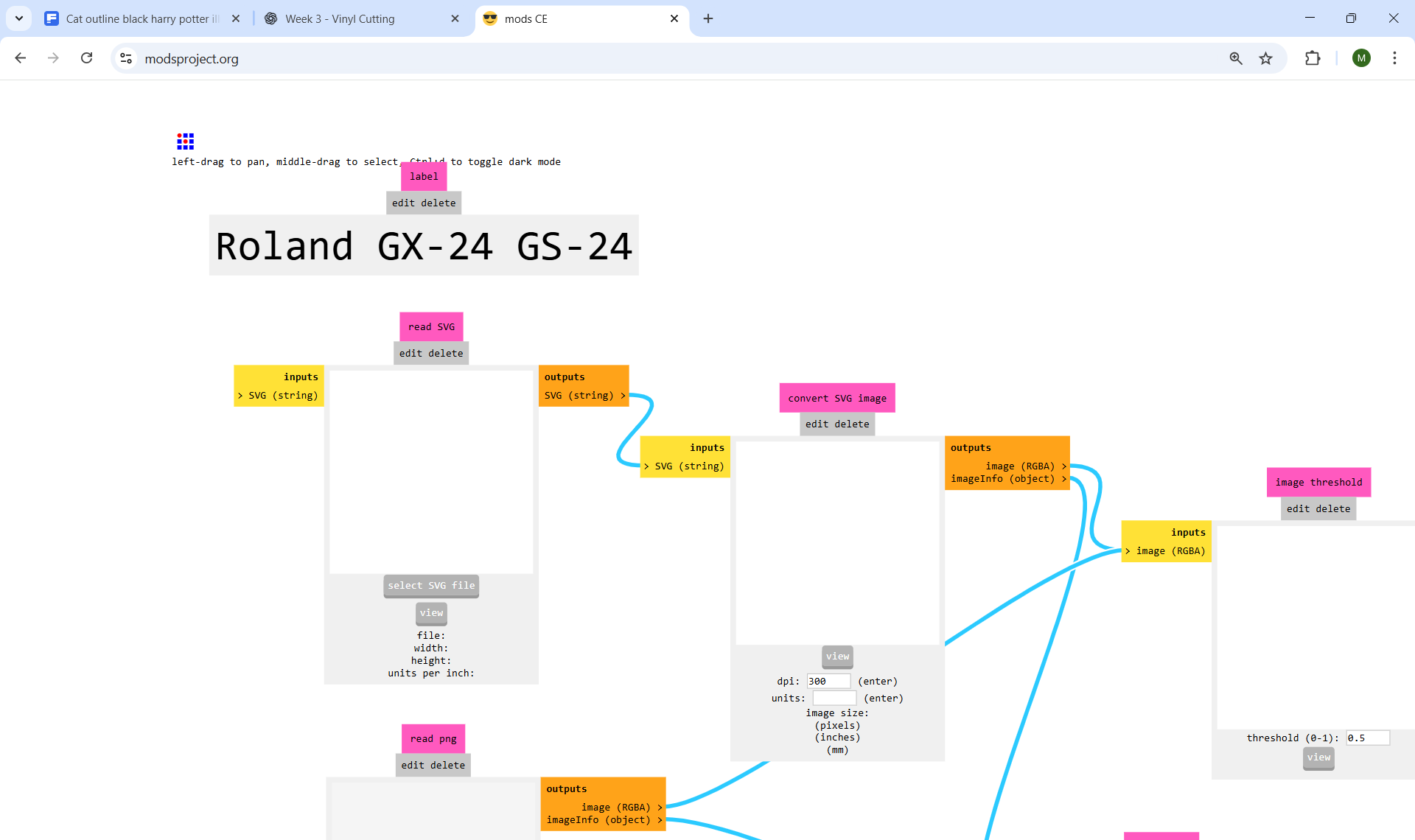
SVG file selection
Fab Modules supports two input formats: SVG files (recommended for clean preservation of vector paths) or PNG raster files (which will be auto-traced).
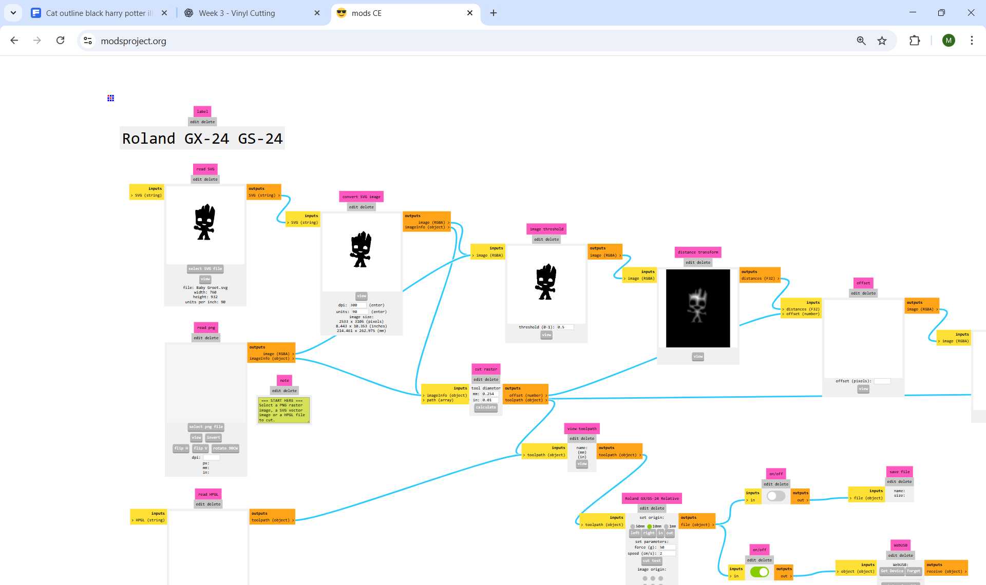
Once loaded, processing nodes automatically populate with the SVG data.
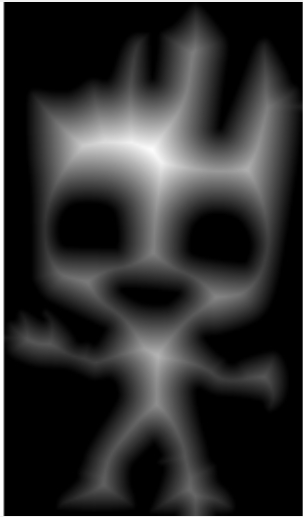
Tool Settings & Path Calculation
After importing the SVG file, minimal parameter adjustment is required:
Default Parameters (Pre-configured for Roland GX-24)
- Tool Diameter: 0.254 mm (matches vinyl cutter blade)
With default settings appropriate for the machine, click Calculate in the cut raster node to generate the cutting toolpath.
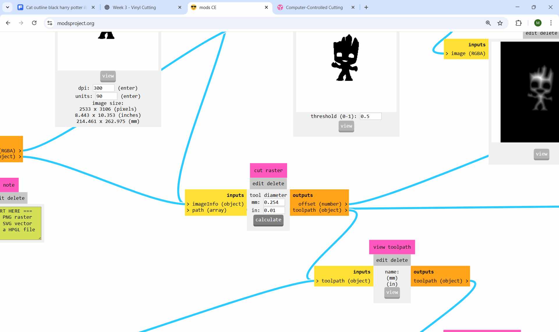
Click Calculate to process the SVG into cutting coordinates.
eeks!!
Visualizing the Cutting Path
After clicking Calculate, the cutting path is visualized in the preview window. This allows verification before sending to the machine.
Path Visualization Guide
- Blue lines: Cutting paths (blade down, vinyl being cut)
- Red lines: Non-cutting movements (blade lifted, rapid travel)
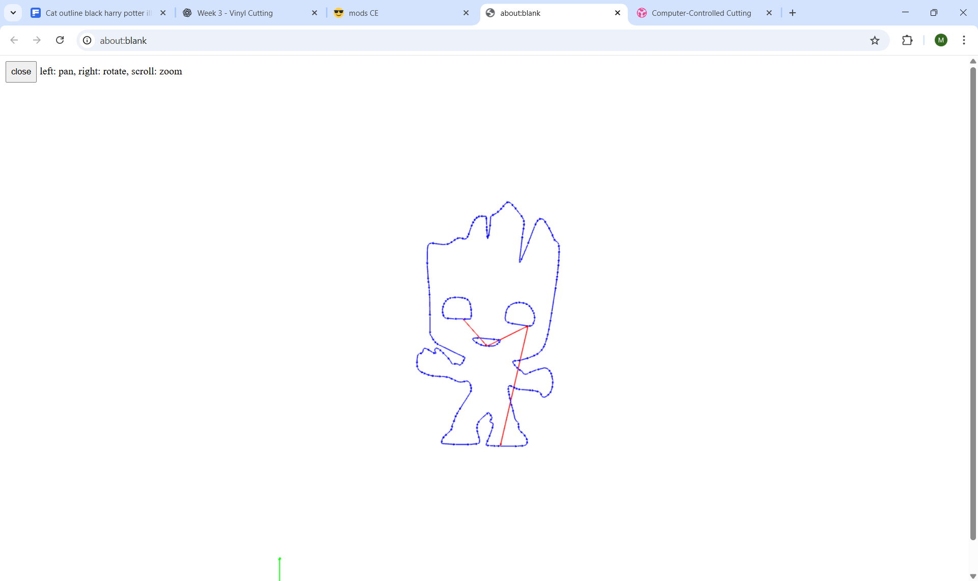
Cutting path preview with color-coded sequences.
Detailed toolpath view showing blade direction changes and movement sequences.
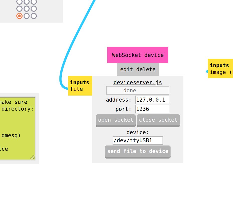
Send file
Click 'Send File' to send the file to the Roland Machine
Operating the Vinyl Cutter
Power & Initial Setup
Power on the vinyl cutter using the main power button (bottom-right of control panel). The machine performs initialization checks, then displays the main menu.
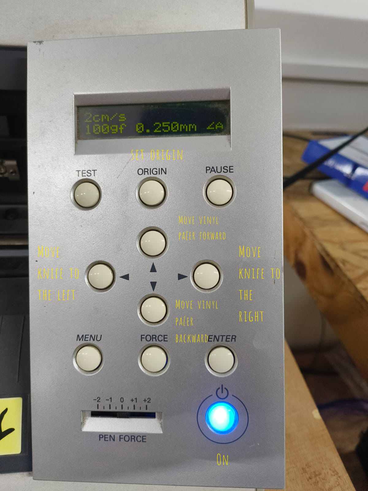
Control panel with power, navigation, and operation buttons.
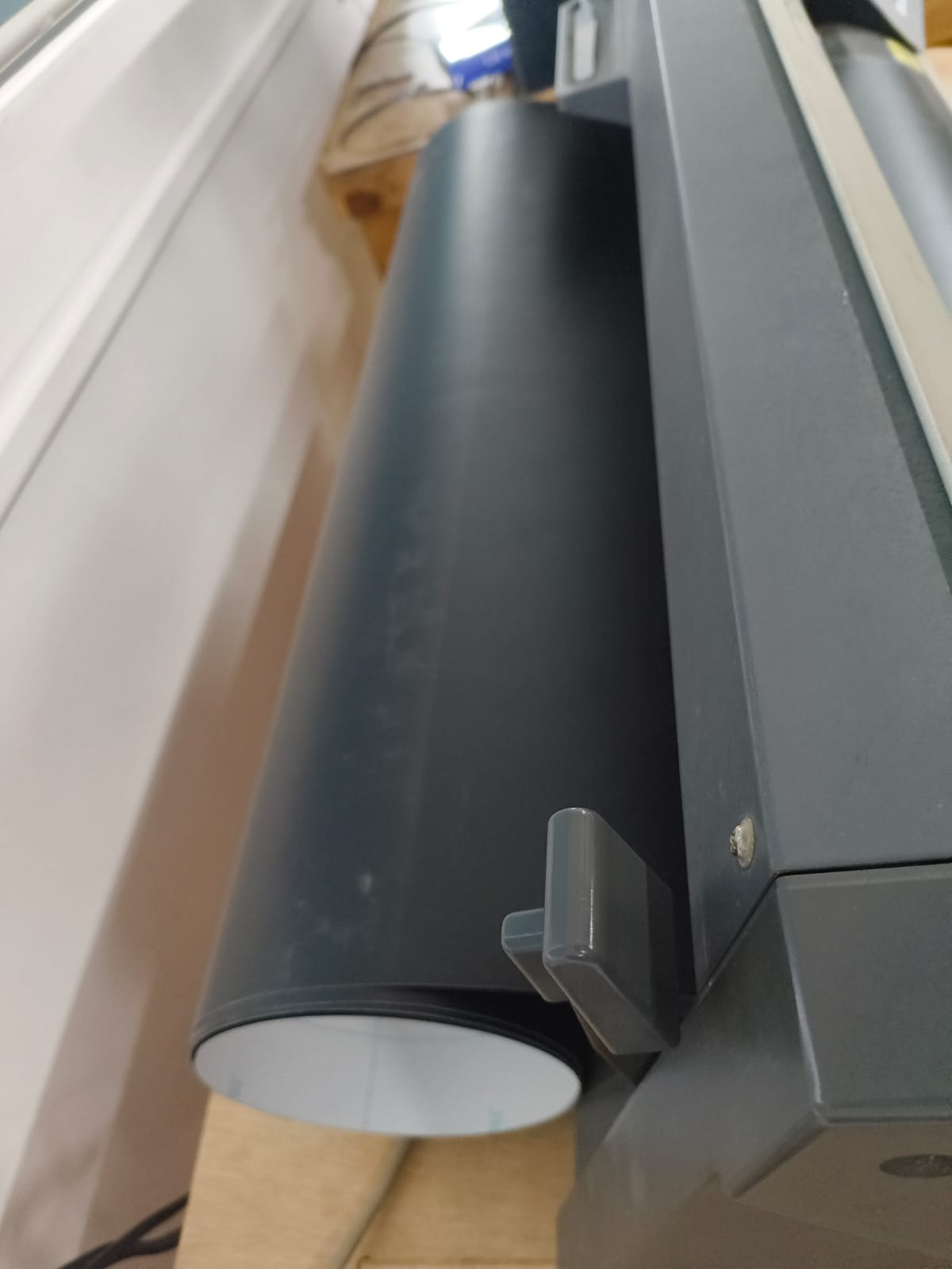
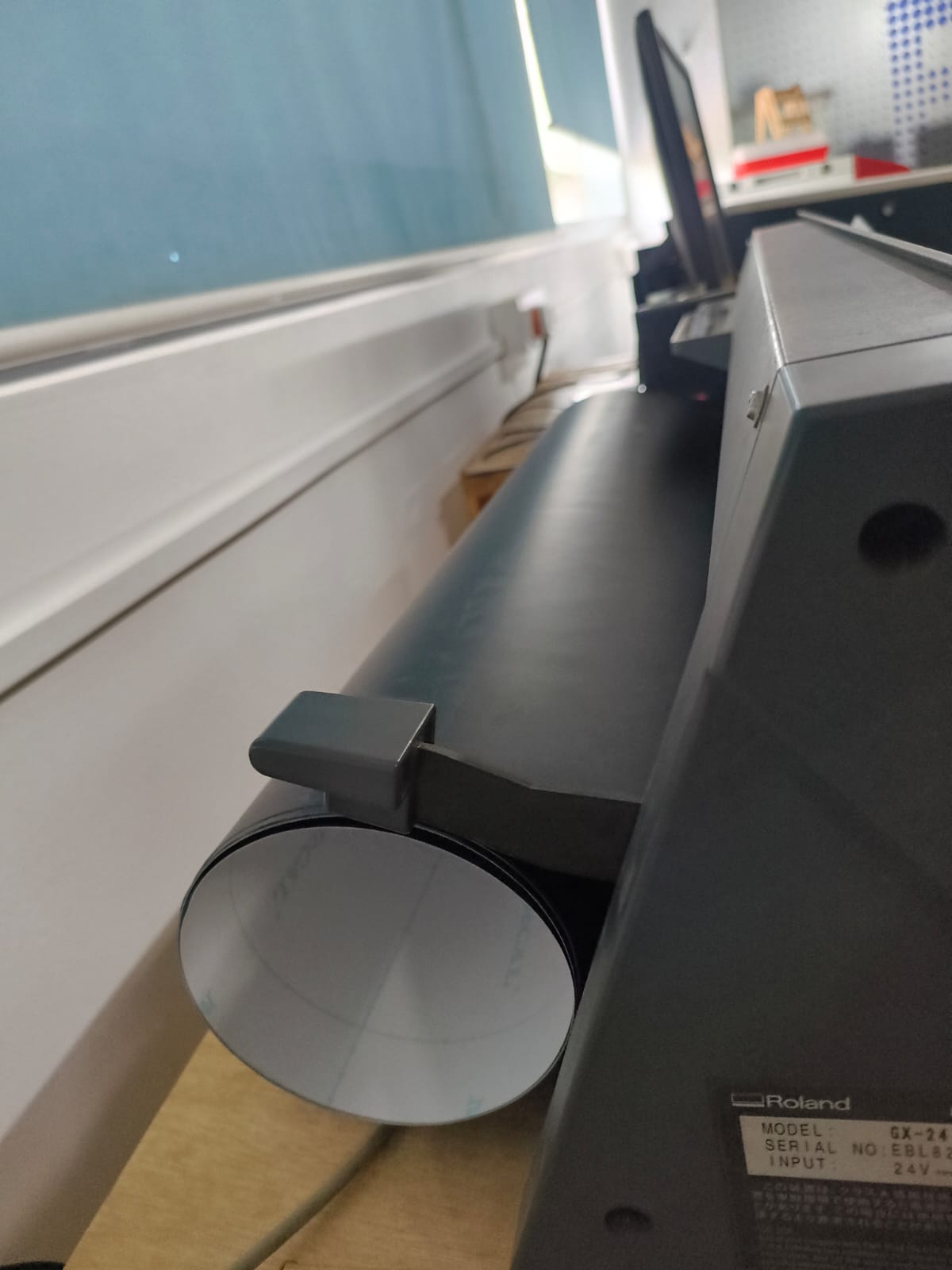
Loading Vinyl Material
- Insert from rear: Feed vinyl from the back of the machine (similar to printer paper)
- Align straight: Ensure material is perfectly straight to prevent skewing
- Position under clamps: Move material under the front clamps/rollers
- Secure firmly: Clamp down to hold material in place
Roll holder setup at rear of machine.
Material loaded and positioned beneath clamps.
Material loaded and positioned beneath clamps.
Pinch Roller Positioning
Pinch rollers grip the vinyl material to prevent slipping during cutting. Correct positioning is essential. Improper placement will cause the machine to refuse operation.
⚠️ WARNING
Pinch rollers MUST be positioned only on the white striped areas of the machine bed. If any roller is placed outside these marked zones, the machine will display a "Bad Position" error and refuse to operate.
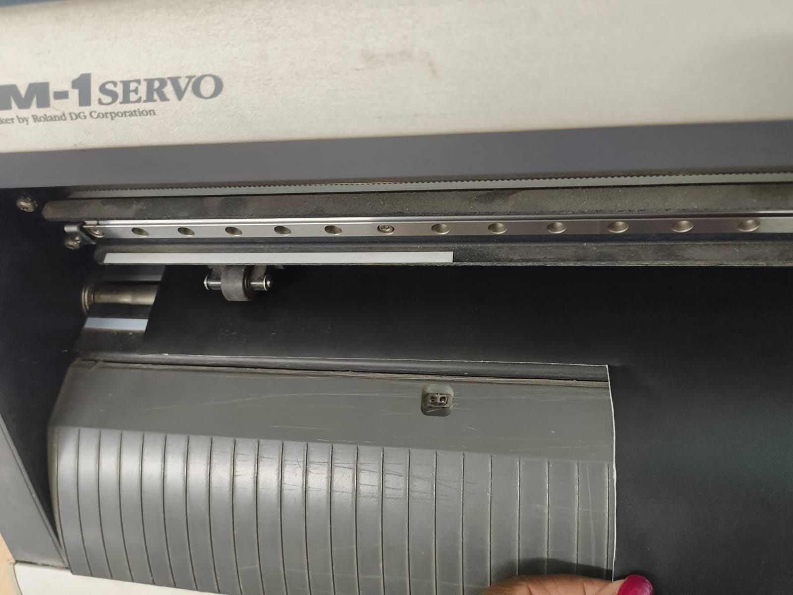
Rollers positioned on white stripes—machine will operate correctly.
Before clamping the Vinyl, position the pinch rollers correctly. Make sure the pinch rollers are positioned above both ends of the paper and clamp down firmly.
Material Type Selection
The machine asks you to specify whether you're using material from a Roll or Piece. Use arrow buttons (▲/▼) to select, then press Enter to confirm.
Roll
- Continuous vinyl roll
- Machine measures width only
- Used for unlimited length designs
Piece
- Individual vinyl sheet
- Machine measures width and length
- Used for predefined sheet sizes
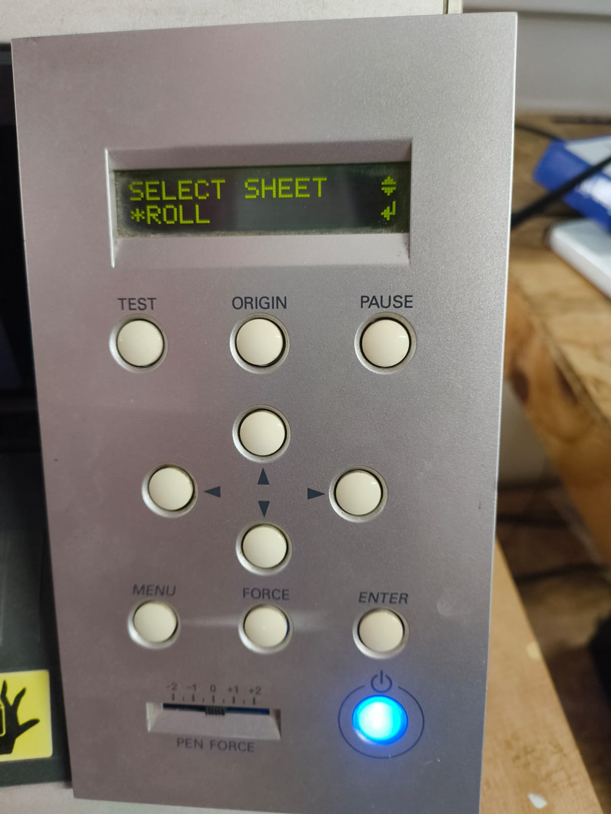
Material type selection menu.
Setting Origin & Executing Cut
- Position blade: Use arrow keys to move blade to desired starting location
- Set origin: Press Origin button to register the cut start position
- Verify parameters: Check cutting force and speed are appropriate for vinyl
- Send file: Transmit the G-code file from Fab Modules to the machine
- Execute: Machine follows vector paths, cutting the Groot design into vinyl
Cutting Parameters Used
- Speed: 1 cm/s
- Force: 100 gf
- Blade Offset: 0.250 mm
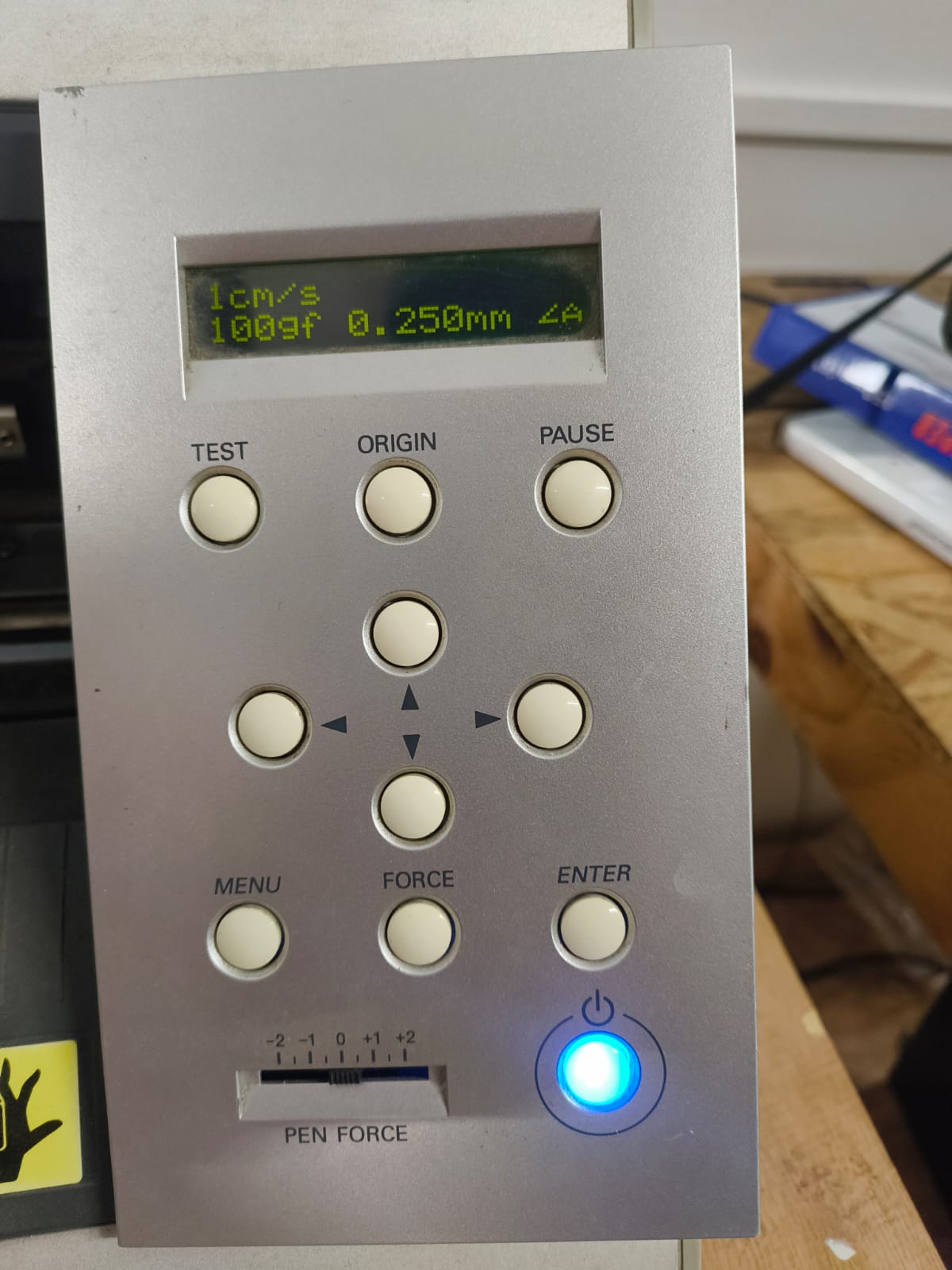
Control panel display showing the cutting parameters used.
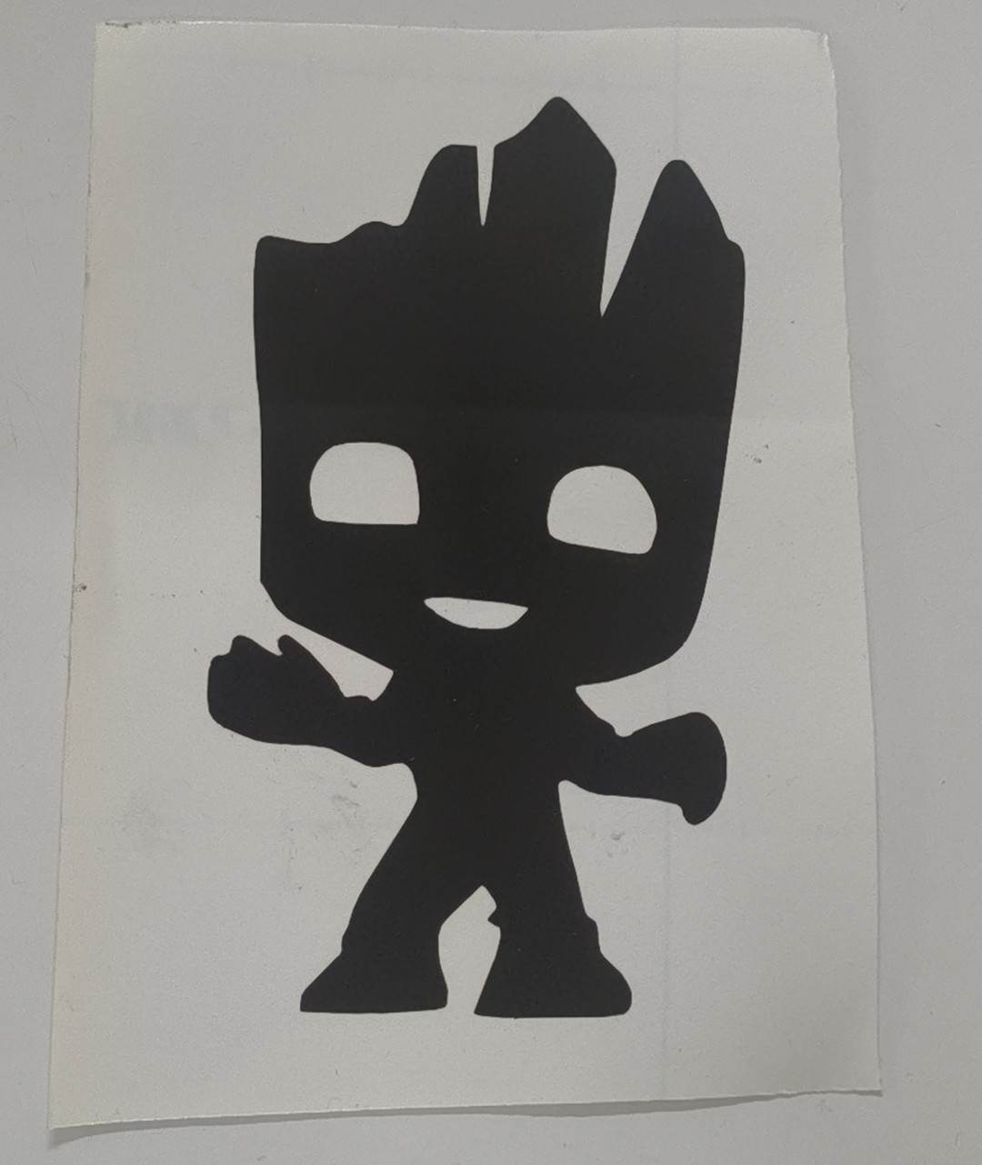
After Weeding
I weeded the vinyl using hand.
Final Result

Final result
✓ Project Complete
The Groot design has been successfully converted from raster to vector format, processed through Fab Modules, and cut into vinyl with clean, precise edges. The passive drag-knife mechanism of the Roland GX-24 produced sharp corners and smooth curves throughout the design.
I didn't use the Transfer paper. My design didn't requie it.
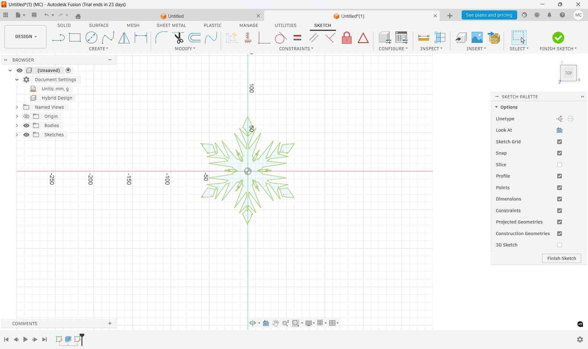
LASER CUTTING
Laser cutting is a thermal cutting technology that uses a focused, high-powered laser beam to cut, engrave, or etch materials with extraordinary precision. Since commercial introduction in the 1960s, laser cutting has become indispensable across manufacturing, creating clean cuts with minimal mechanical stress on the workpiece.
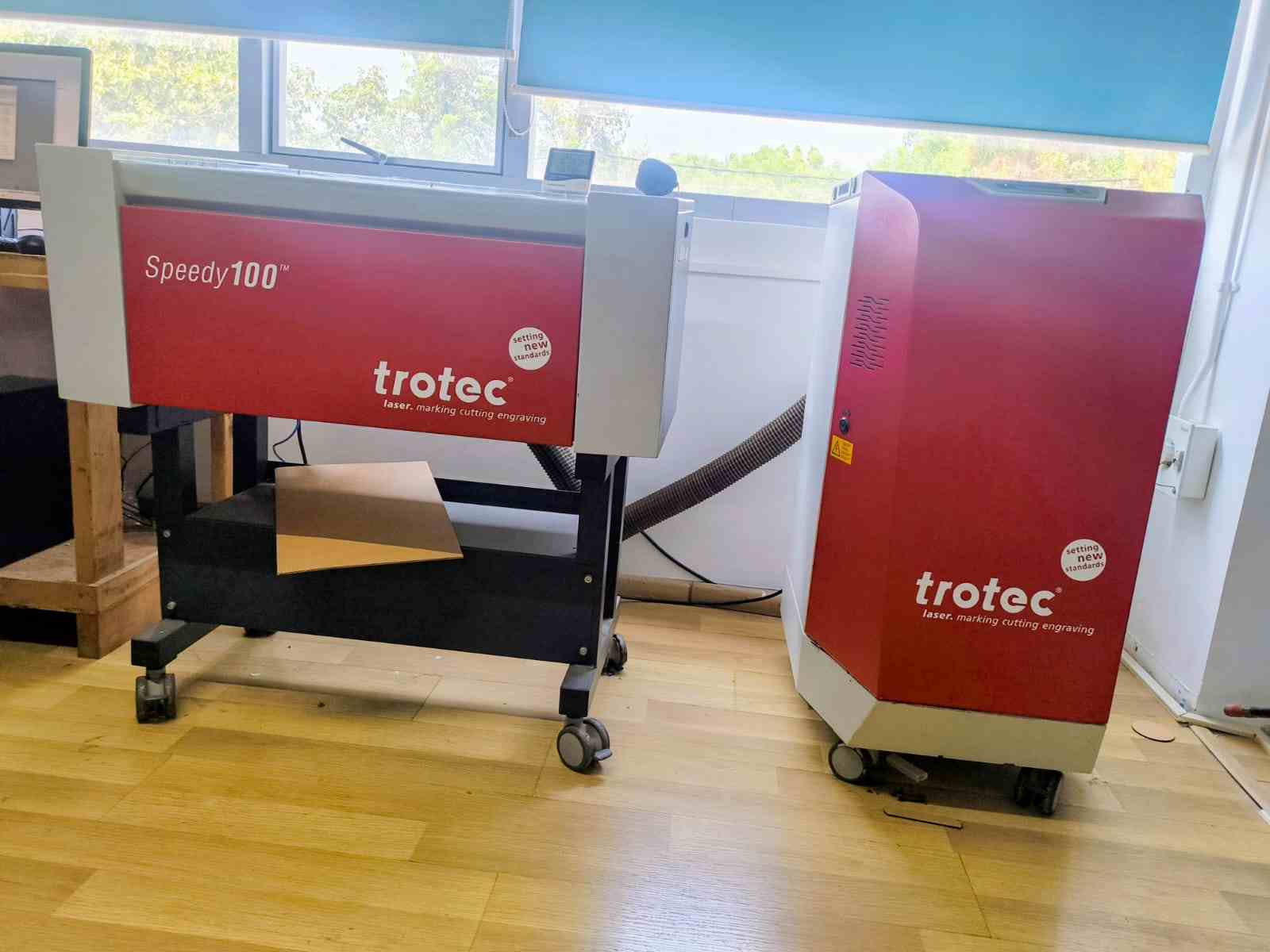
The Trotec Speedy 100 CO2 laser cutter used for our fabrication projects.
Manufacturer link for Laser Cutter
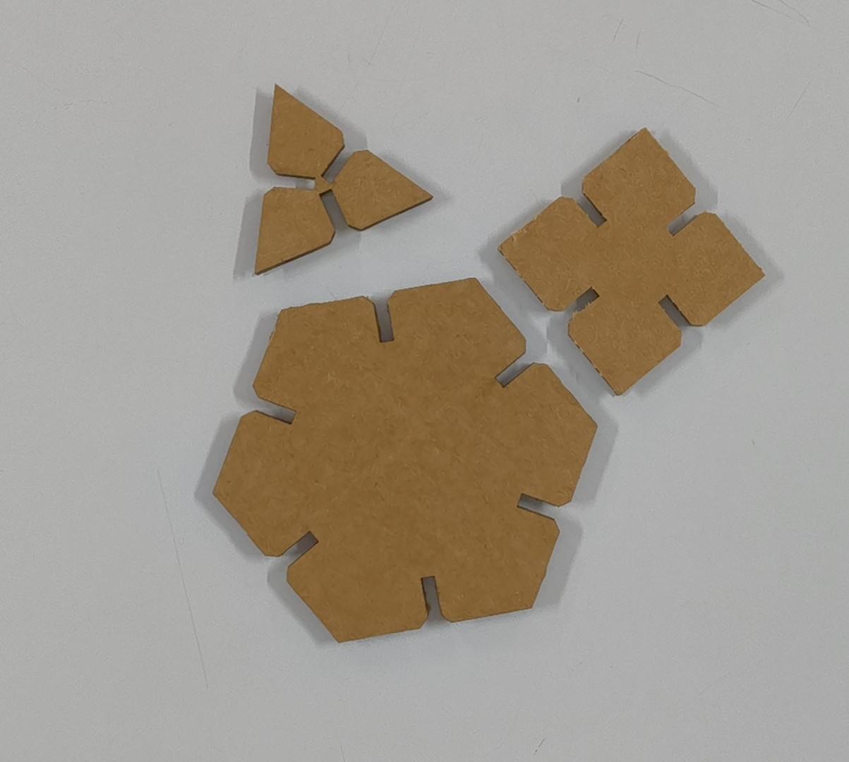
Laser Cutting Construction Kit
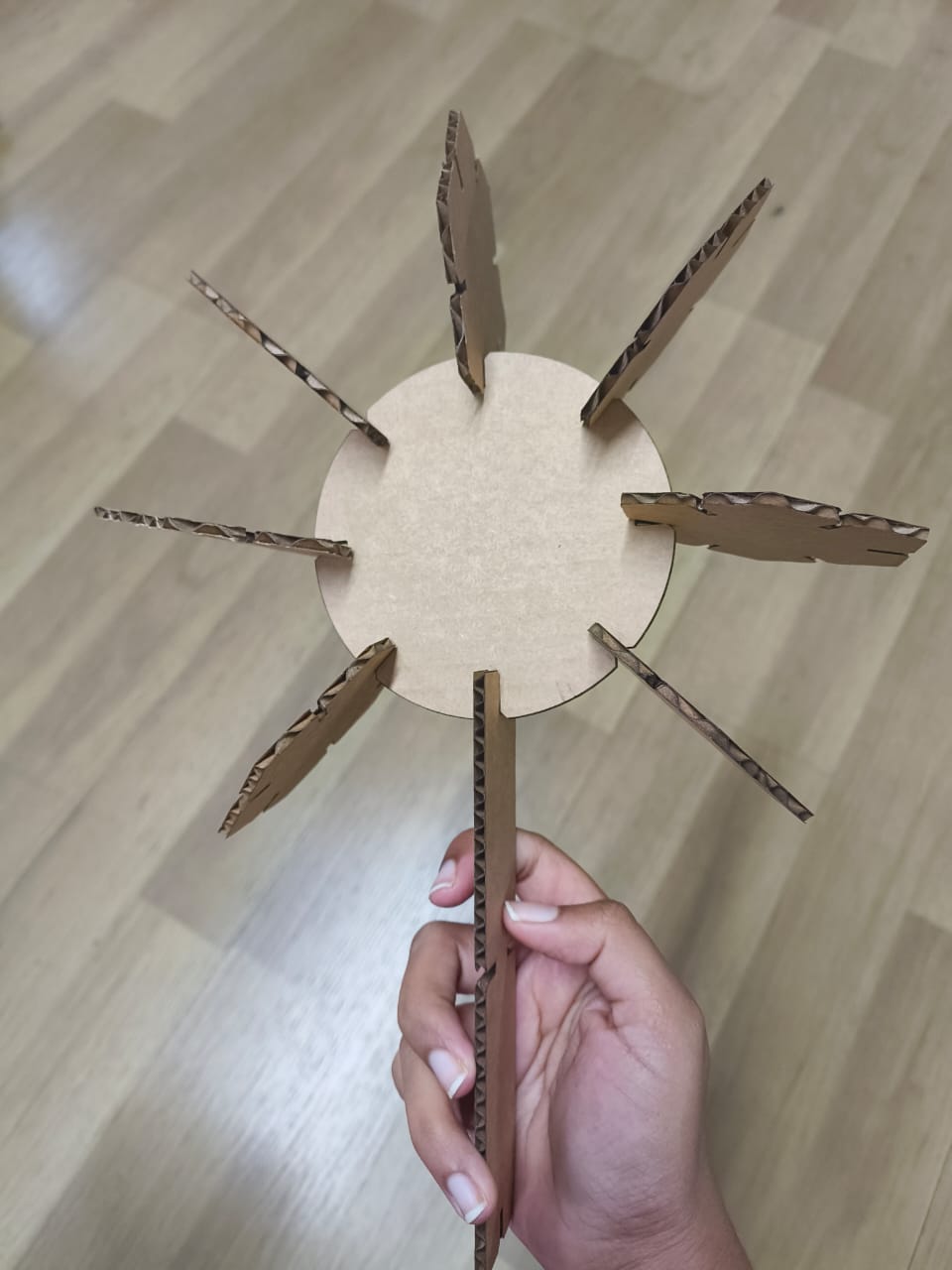
For this project, I designed a parametric construction kit with interlocking pieces that account for laser kerf. The kit demonstrates print-in-place principles where individual pieces slot together without additional fasteners or assembly.
Design Tools & Materials
| Tool/Material | Purpose |
|---|---|
| Autodesk Fusion 360 | Parametric design, sketching, and constraint-based modeling |
| Trotec Speedy 100 | CO2 laser cutting and engraving |
| Calipers | Measure material thickness precisely |
| Sheet Material | Cardboard, plywood, or acrylic (3-5mm thickness) |
Design Process: Parametric Construction Kit
Step 1: Source Design Image
The design process began with a Frozen movie ice motif image, downloaded as inspiration for the decorative engraving element.

Source image: Frozen ice pattern for construction kit engraving.
You can get the image from here
Step 2: Convert Raster to Vector
The JPG was imported into Inkscape and converted to vector format using Path → Trace Bitmap. This created clean, scalable paths suitable for laser engraving.

Vector paths extracted from raster image—ready for laser engraving.
Step 3: Import SVG into Fusion 360
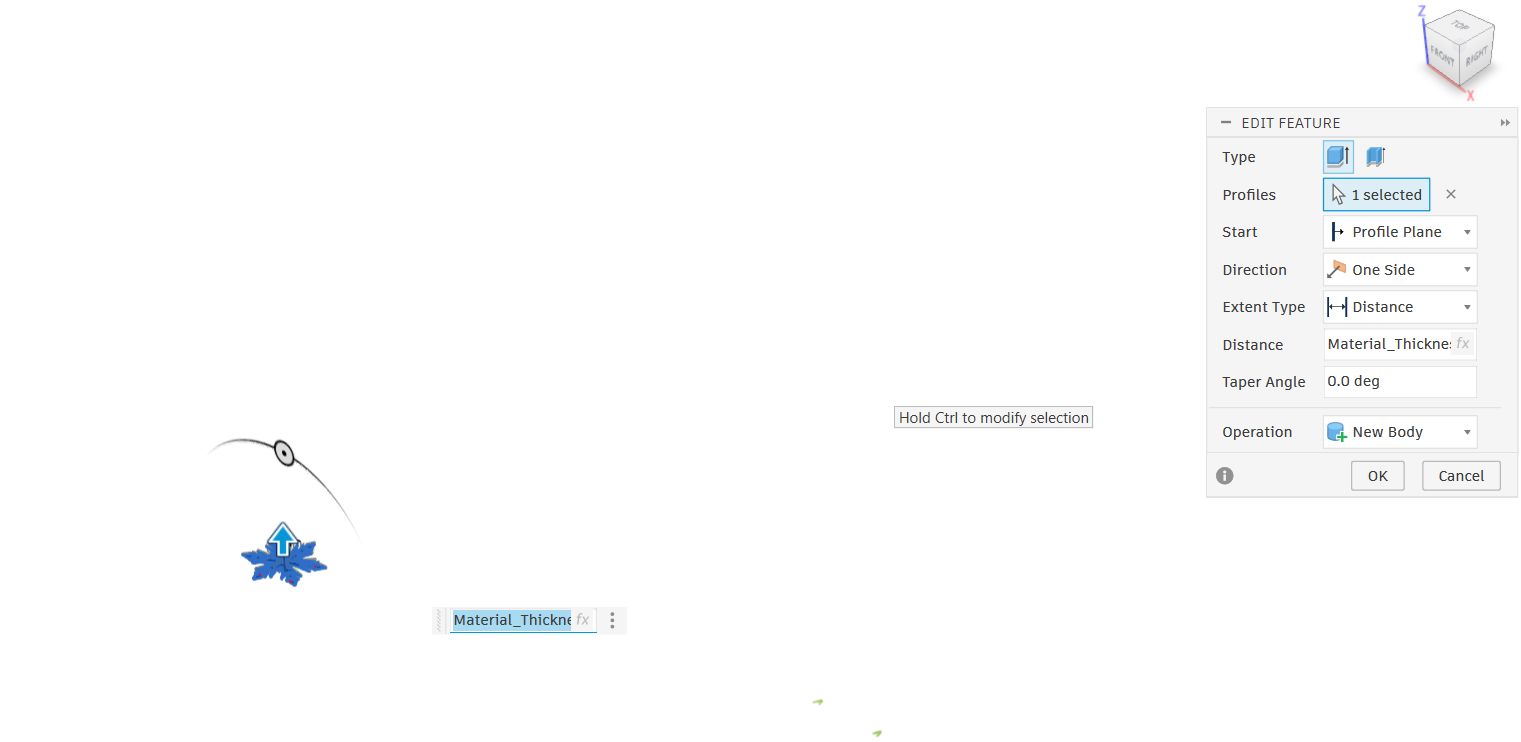
The SVG file was imported into Fusion 360 as the central decorative element. Two concentric circles were drawn around it to define the structural boundary of each kit piece.
Fusion 360 sketch showing engraving motif and structural geometry.
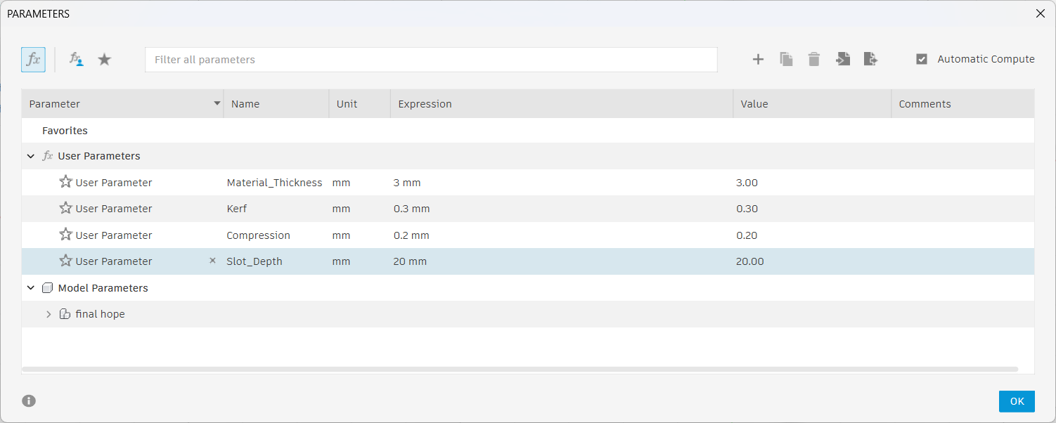
Step 4: Define Parametric Parameters
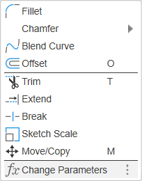
Parameters were created for key dimensions: material thickness, kerf, compression, and slot width. The slot width was calculated as: Slot Width = Material Thickness − Kerf − Compression
To add parameters, select Modify → Change Parameters, then click the plus button to create new parameters.
Parameters dialog showing material and tolerance values.
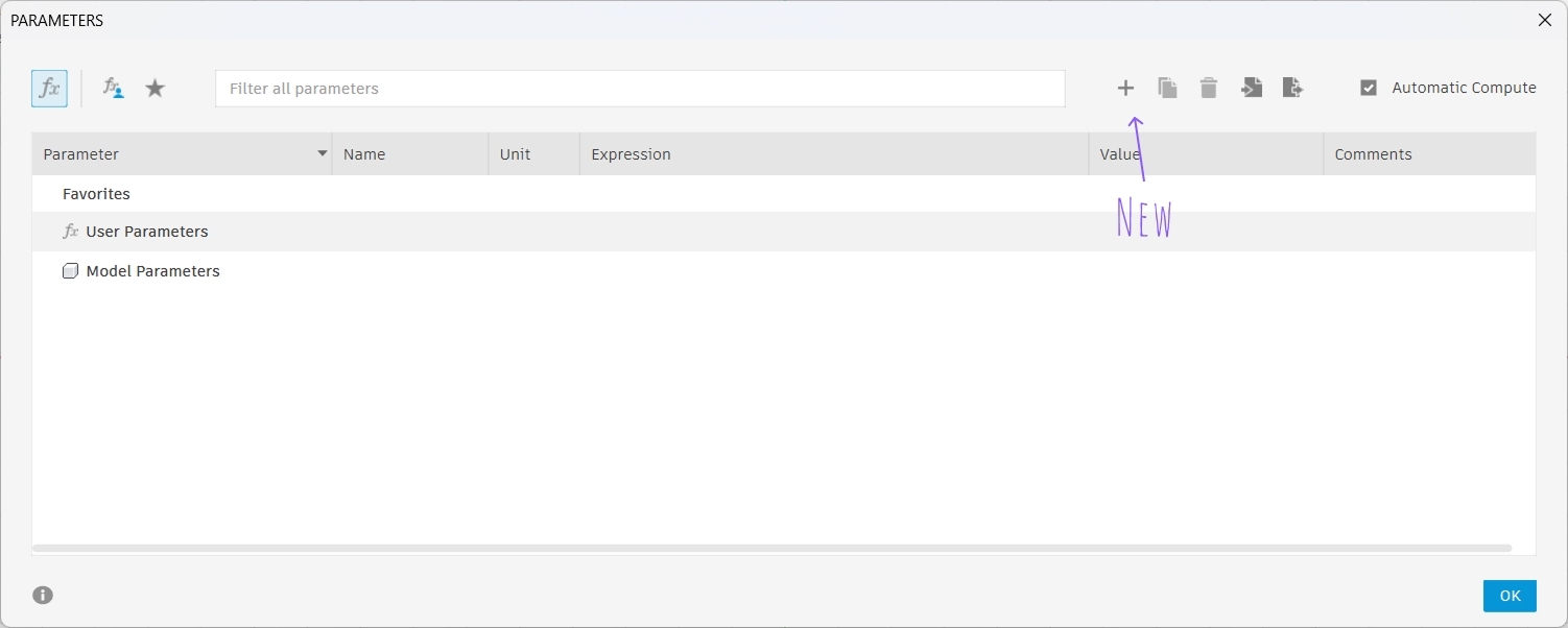
Click the plus button to add new parameters.
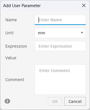
Parameter entry dialog.
Key Parameters Created
- Material Thickness: 3mm (measured with calipers)
- Kerf: 0.15mm (from group characterization tests)
- Compression: 0.2mm (tolerance for tight press-fit)
- Slot Width Formula: Material Thickness − Kerf − Compression = 2.65mm
Parameter list showing all dimensional constraints for the kit.
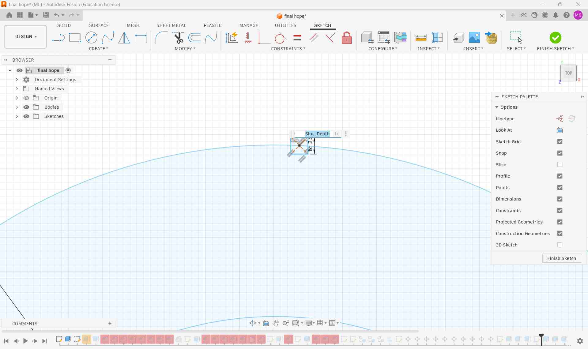
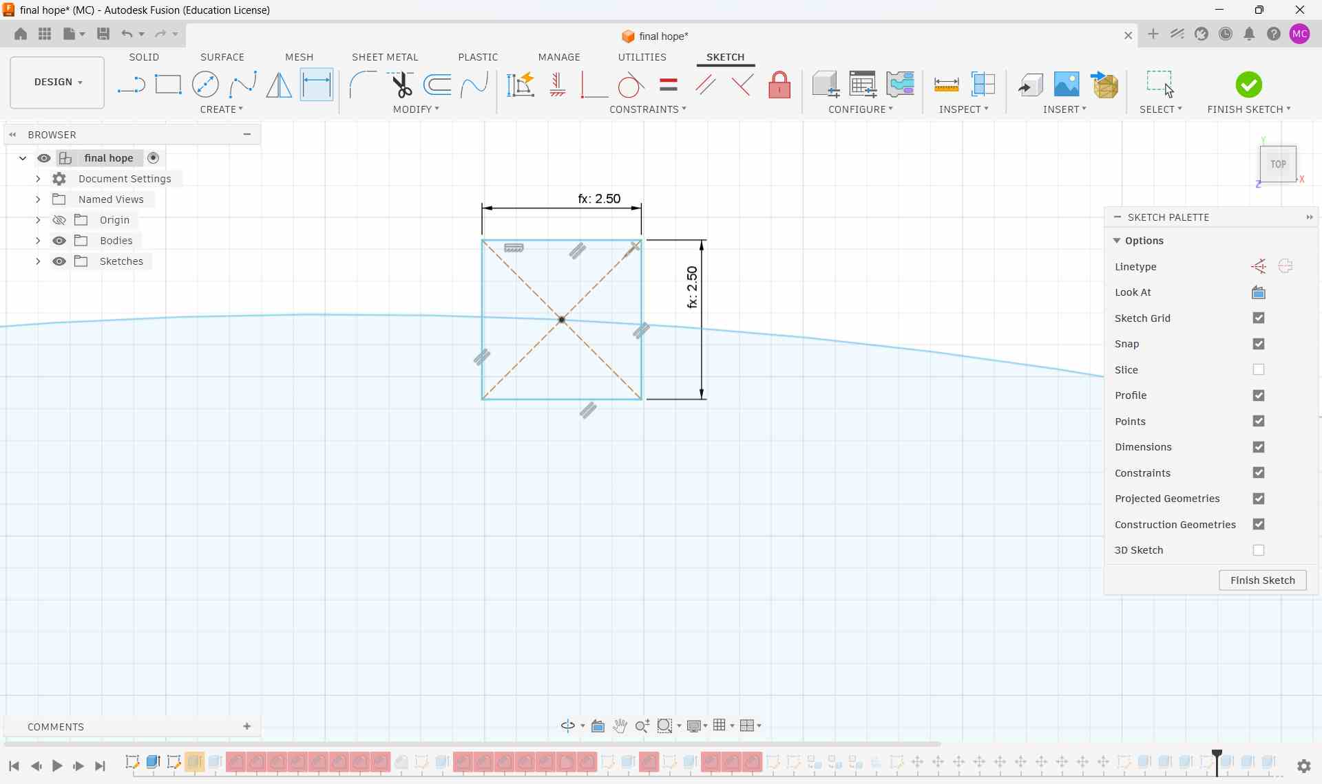
Step 5: Create Slot Geometry
A center rectangle was created with:
- Width: Calculated slot width parameter (2.65mm)
- Height: Material thickness (3mm)
Using Create → Circular Pattern, multiple slots were arrayed radially around each piece, creating a symmetric pattern for interlocking assembly.
Step 6: Complete Design & Extrusion
Additional decorative elements were added, and the entire sketch was extruded to create 3D geometry. The extrusion depth was set to match material thickness.
Then I added new designs.
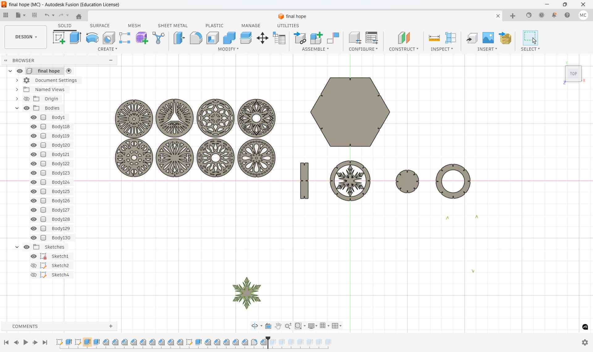
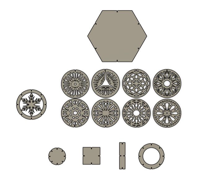
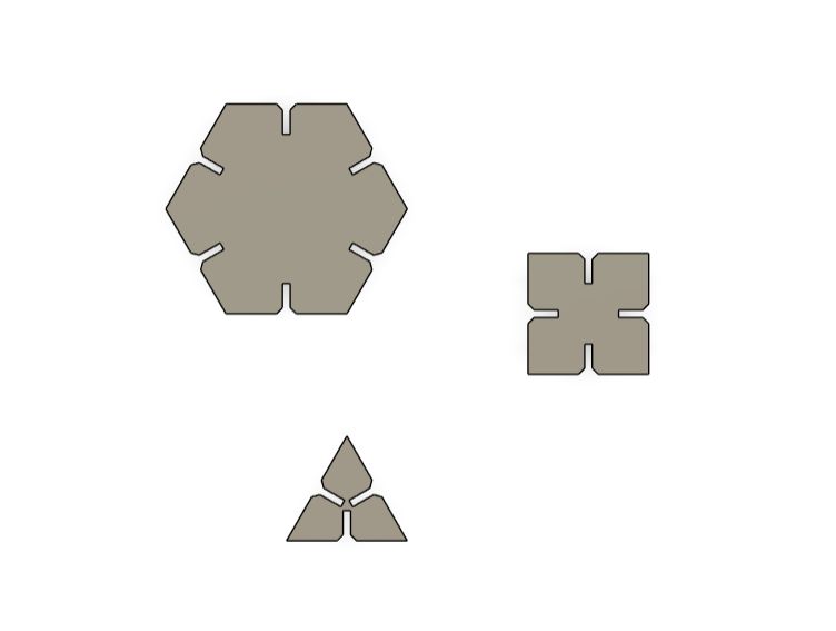
Completed construction kit design with parametrically-defined slots and decorative engravings.
Step 7: Project Components onto a New Sketch & Export as DXF
With all components designed and arranged in 3D space, the next step was to prepare the flat cutting profiles for the laser cutter. This involved projecting the 3D geometry back onto a 2D sketch plane and exporting in a format the laser cutter software can understand.
- Create a new sketch on the XY plane (or any flat reference plane that aligns with the material surface)
- Modify → Project/Include → Project (P shortcut in Fusion 360) to project the body edges onto the sketch. Select all relevant faces — outer boundary, inner slot edges, and any decorative cut lines
- Verify the projected profiles: Confirm all slots, circles, and cut paths appear correctly as 2D sketch entities with no gaps or overlapping geometry
- Finish the sketch once all profiles are cleanly projected
Exporting as DXF
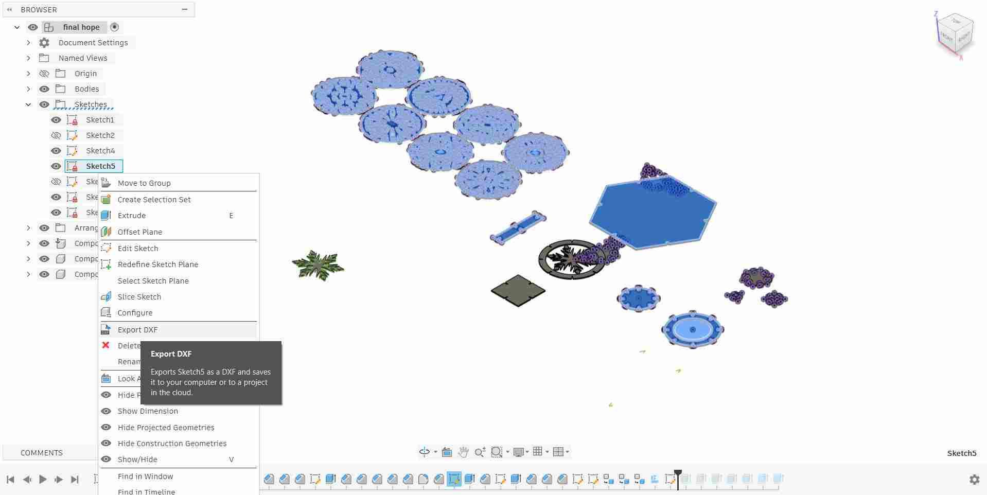
Once the projected sketch was verified, the design was exported as a DXF (Drawing Exchange Format) file
- Right-click on the sketch in the browser tree → select Save As DXF
- Choose a save location and filename (e.g.,
construction_kit_v1.dxf) - Fusion 360 exports all sketch geometry as 2D vector entities: lines, arcs, and circles
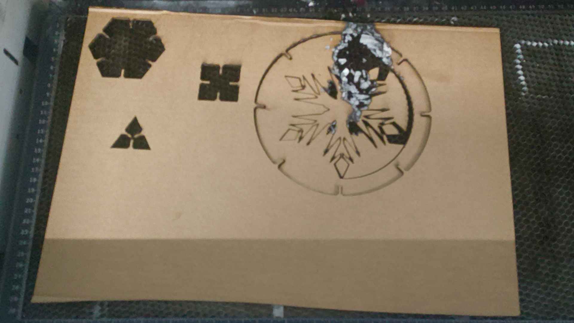
This design was abandoned cause the instructors warned me that the design cuts will be too small. So I made a test cut instead.
It ended up burning. So I abandoned the design.
Then I went and design a new one.
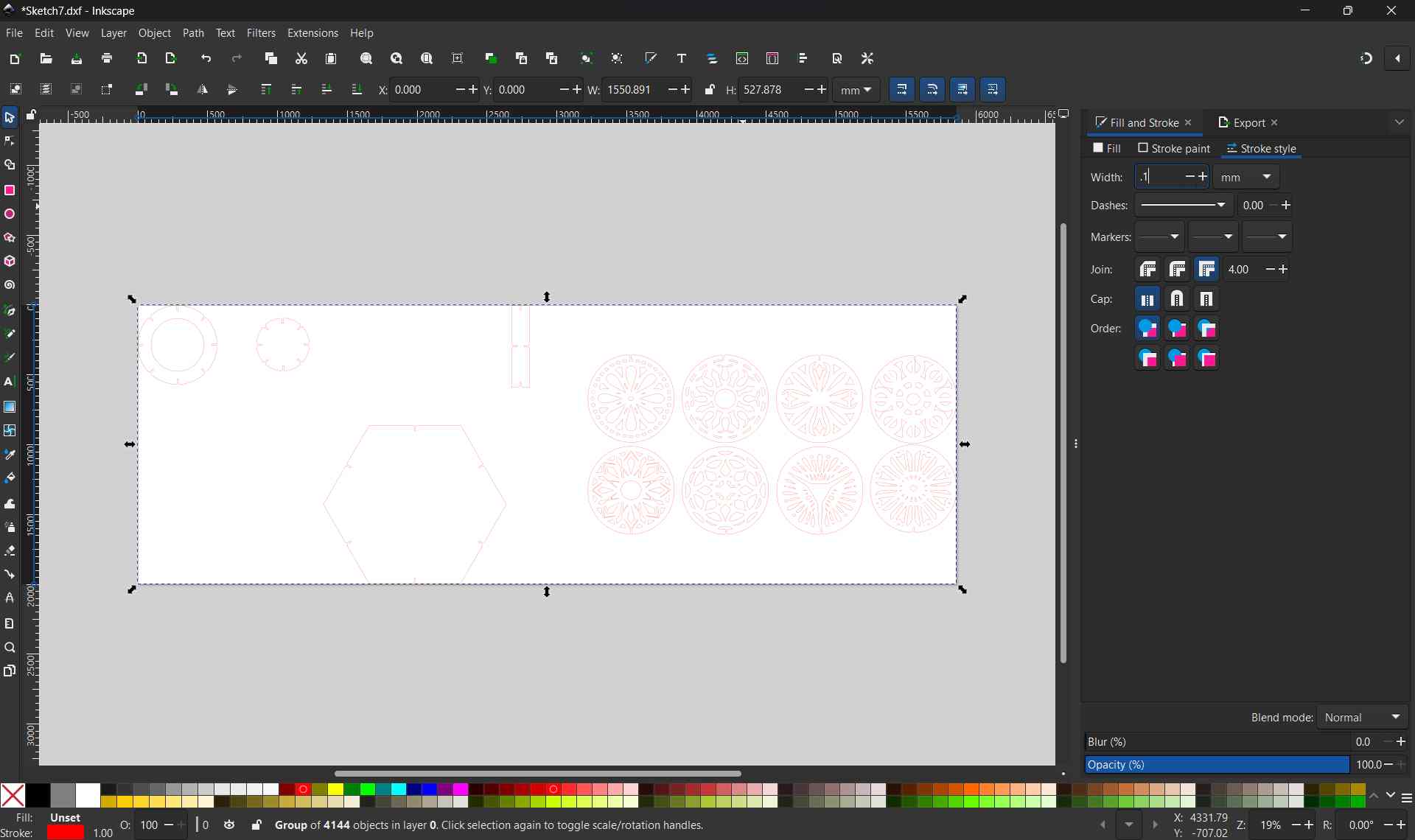
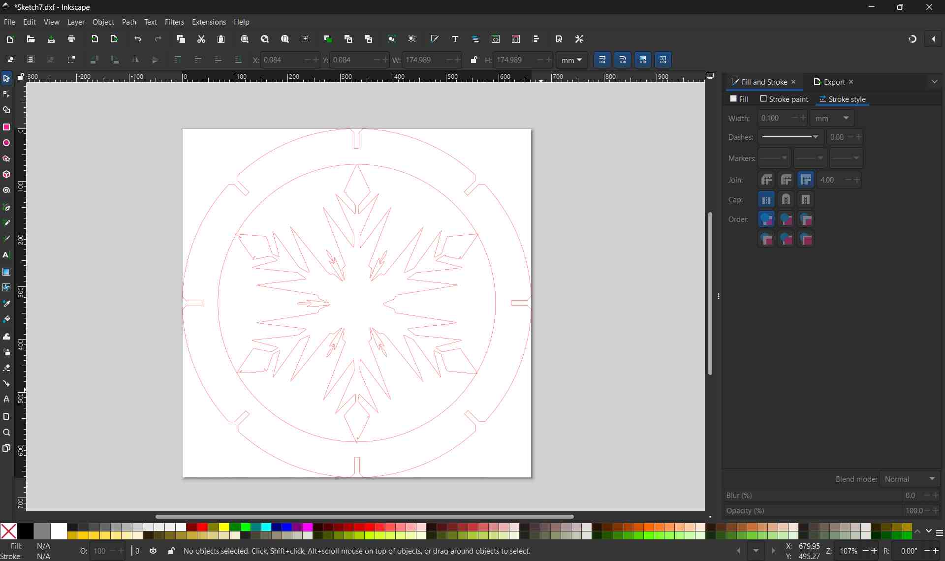
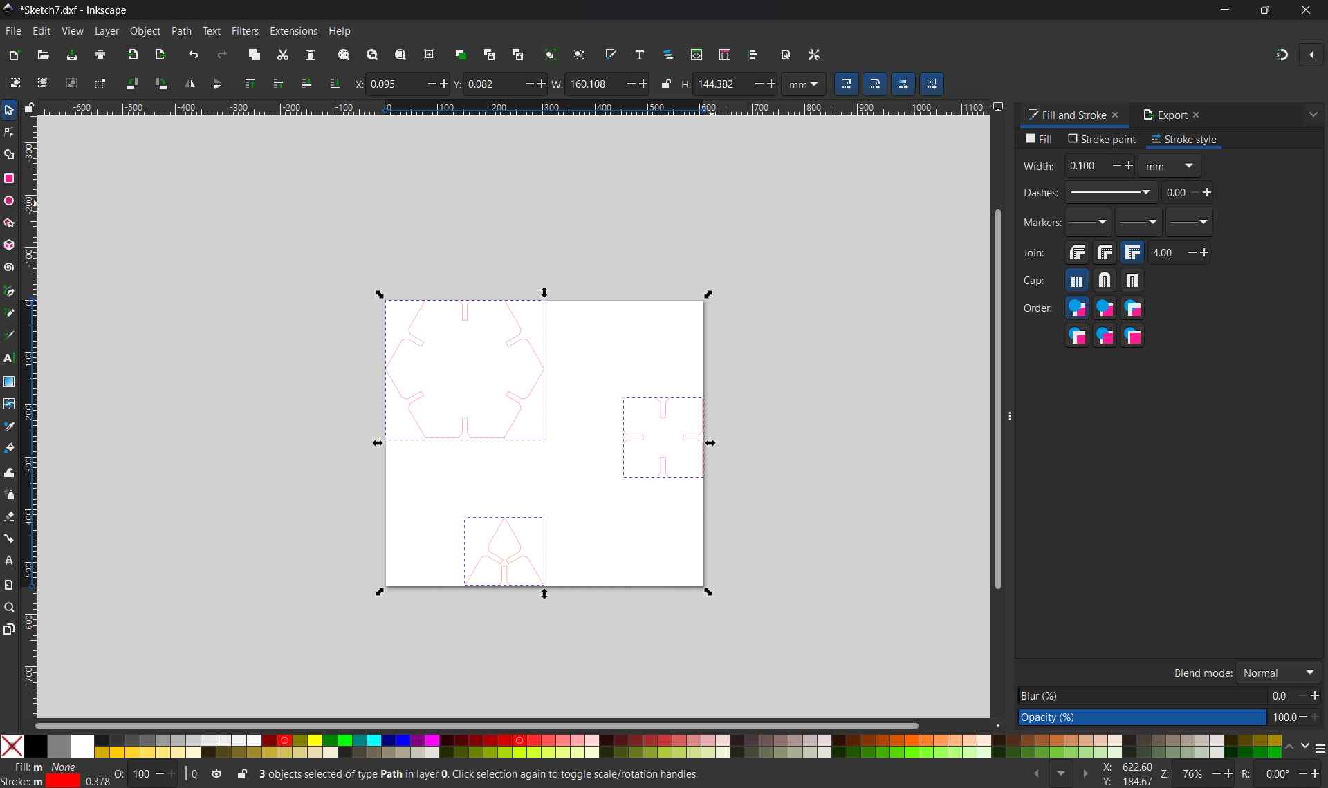
Step 8: Inkscape Workflow — Preparing the DXF for the Laser Cutter
With the DXF file exported from Fusion 360, it was imported into Inkscape to prepare the final cut file. Inkscape acts as the bridge between the CAD design and the Trotec laser cutter, allowing line colors and stroke properties to be assigned so the machine knows which paths to cut and which to engrave.
1. Import the DXF File
- Open Inkscape → File → Import (or drag and drop the DXF file)
- Select all components (Ctrl+A)
- Press Ctrl+Shift+R this fits the canvas exactly around all imported components
2. Verify Scale & Dimensions
- Select all geometry (Ctrl+A) and check the width/height in the toolbar, they should match the designed dimensions exactly
- If dimensions are off, use File → Document Properties to confirm the document unit is set to mm
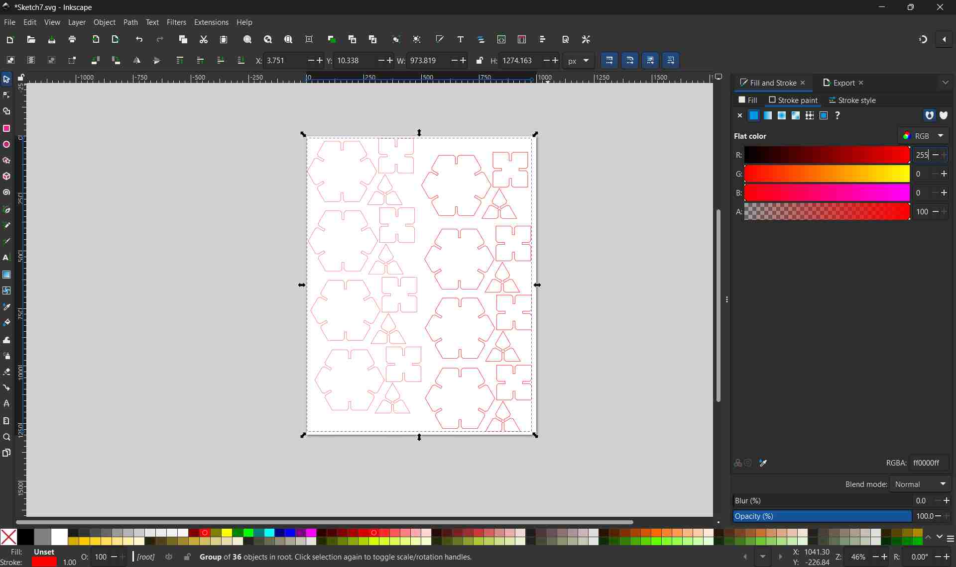
3. Assign Line Colors for Cut vs Engrave
The Trotec laser cutter reads line color to determine the operation type. Each color maps to a separate job in Trotec JobControl with its own power and speed settings.
Cut Lines — Red
- Stroke color: R=255, G=0, B=0
- Stroke width: 0.1 mm (hairline — the thinnest possible)
- Fill: None
- Used for: outer boundary, slots, through-cuts
Engrave Lines — Black
- Stroke color: R=0, G=0, B=0
- Stroke width: any visible width
- Fill: None
- Used for: Frozen ice motif decoration
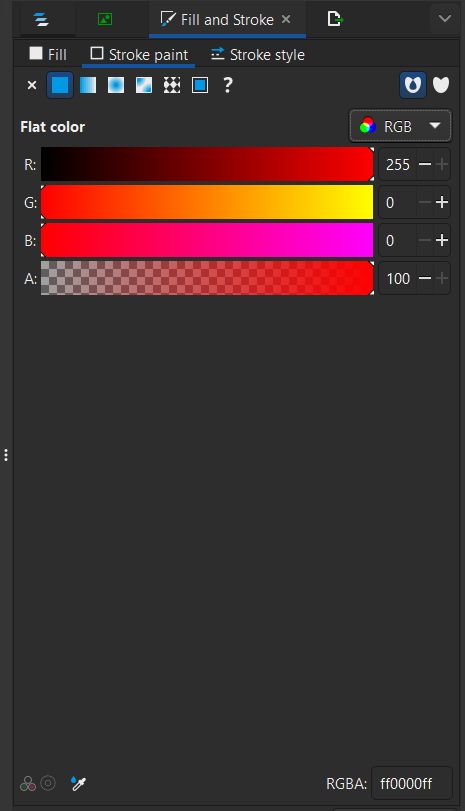

⚠️ No Fill — Strokes Only
The Trotec laser cutter software only reads stroke paths as input — filled shapes are ignored. All paths (both cut and engrave) must have Fill set to None in the Fill and Stroke dialog (Shift+Ctrl+F). Only the stroke color and width determine how the machine processes each path.
4. Group & Arrange Components
- Select all cut-line geometry → assign red hairline stroke via Object → Fill and Stroke (Shift+Ctrl+F)
- Select all engraving geometry → assign black fill
- Arrange all pieces within the material boundary — keep a 5–10 mm margin from edges
- Nest pieces efficiently to minimize material waste
5. Print to Trotec JobControl
- Go to File → Print (Ctrl+P)
- Select Trotec Engraver as the printer
- Click Print — this sends the job directly to Trotec JobControl
- In JobControl, the cut lines and engrave areas appear as separate color-coded layers, each assignable to power/speed profiles
✓ Ready to Cut
With the file printed to JobControl, the correct power and speed settings were assigned per layer, the material was placed and focused on the bed, and the job was sent to the Trotec Speedy 100 for cutting.
Machine Setup & Focusing
Adjustable Bed System
The Trotec laser cutter has an electronically controlled adjustable bed that moves vertically using internal motors. The focal distance between the laser head and material is critical for cutting accuracy.
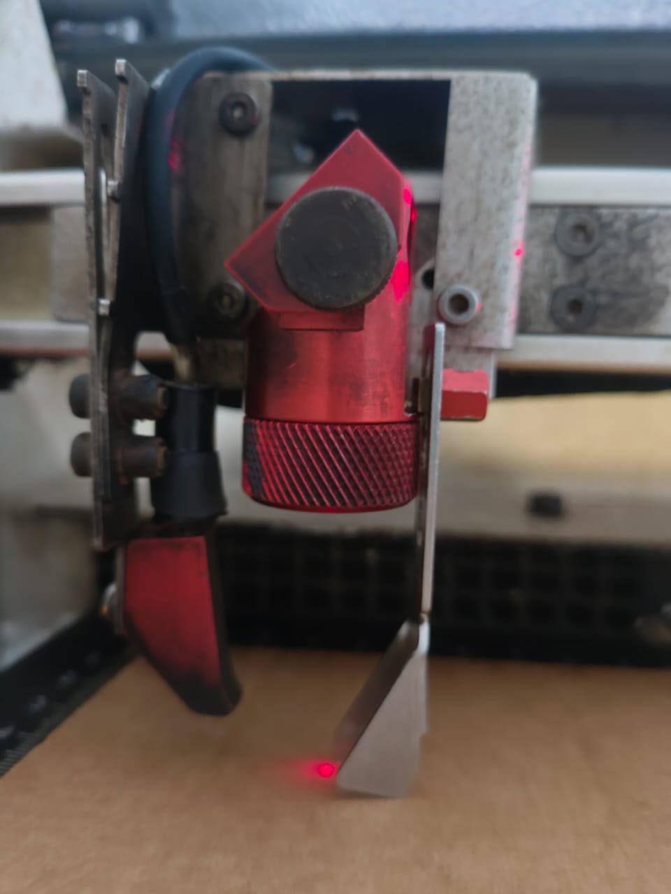
Adjustable bed raises/lowers to maintain precise focus distance.
Control Panel: Bed Adjustment
- ▲ Up arrow: Raises the bed (moves material closer to laser)
- ▼ Down arrow: Lowers the bed (moves material away from laser)
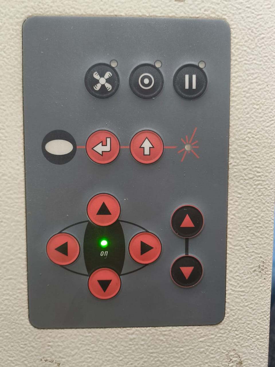
Control panel showing bed movement controls.
Focus Calibration (Critical for Precision Cutting)
- Place material on the bed
- Use up/down buttons to position bed approximately
- Use the Trotec focus gauge (official focus tool) to set exact focal height
- Adjust bed until focus gauge just touches the material surface—this is the focal point
- At correct focus, laser beam converges to minimum beam diameter for optimal cutting
⚠️ Why Focus Matters
Incorrect focus causes:
- Poor kerf: Inconsistent cut width across material thickness
- Rough edges: Burning or melting at material edges
- Failed cuts: Beam unfocused, insufficient power at surface
- Weak press-fits: Slots too wide or too narrow for proper assembly
Cutting Parameters
After the file is sent from Inkscape to Trotec JobControl via the print dialog, each color layer appears as a separate job entry.
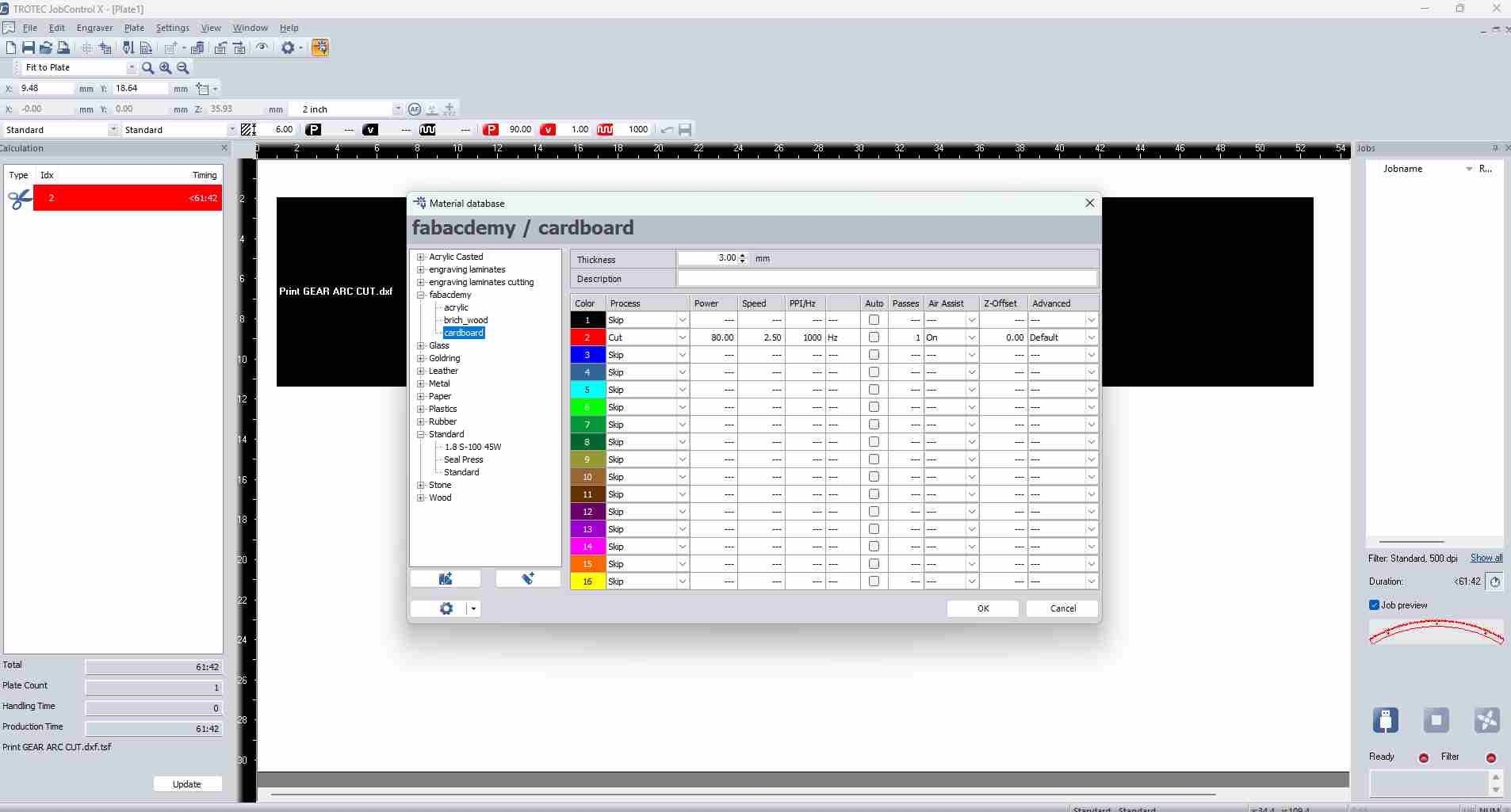
Understanding the Three Key Parameters
- Power (%): Controls laser beam intensity. Higher power cuts deeper but risks burning edges or blow-through on thin materials.
- Speed (%): Controls how fast the laser head moves across the material. Lower speed means longer exposure and more energy per millimetre.
- Passes: Number of times the laser traces the same path. A single pass at high power is generally preferred over multiple passes to reduce heat spread.
Parameters Used for This Job
| Layer / Operation | Power (%) | Speed (%) | Passes | Notes |
|---|---|---|---|---|
| Cut (red hairline) | 80 | 2.5 | 1 | Full cut through 3mm cardboard |
| Engrave (black fill) | 20 | 10 | 1 | Surface raster engraving, no cut-through |
Cutting Results
Once the file is prepared and machine is focused, the laser cutter executes the digital design, cutting all slots and engraving decorative elements in a single operation.
Prior to cutting the final design, a test cut was executed using a separate file.
After the test was successful, I went for mass manufacturng.
I arranged the design below by copying and pasting by hand.
Arranging Components with Fusion 360's Arrange Function
Instead of arranging components manually, Fusion 360 provides an "Arrange" function that automatically positions components on a flat plane.
You can go to Modify --> Arrange
Arrange only works on components, not bodies. Before using it, each body in the design must be converted to a component:
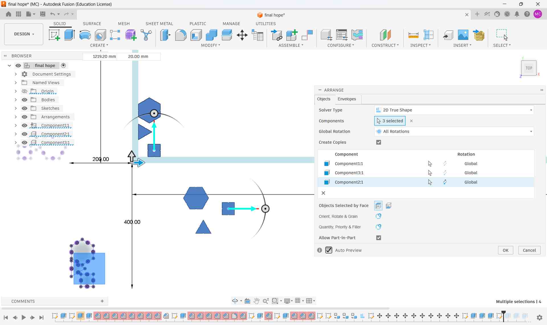
I did not use arrange function in my workflow. Instead I arranged the components manually.