EMBEDDED PROGRAMMING
Group Assignment
- Demonstrate and compare the toolchains and development workflows for available embedded architectures.
Individual Assignment
- Browse through the datasheet for a microcontroller.
- Write and test a program for an embedded system using a microcontroller to interact (with input and/or output devices) and communicate (with wired or wireless connections).
- Extra credit: Assemble the system.
- Extra credit: Try different languages and/or development environments.
You can view the goup assignment here.
Overview
This week marks my journey into embedded programming using the Seeed Studio XIAO RP2040 board. The RP2040, powered by Raspberry Pi's dual Cortex-M0+ cores, serves as my platform for learning how to write code that directly controls hardware - from blinking LEDs to reading sensors and creating interactive projects.
Seeed Studio XIAO RP2040
Specification
| Product Name | Seeed Studio XIAO RP2040 |
|---|---|
| Chipset | Silicon — Raspberry Pi |
| Processor | Dual Cortex M0+ @ up to 133 MHz |
| RAM | 264 KB SRAM |
| Flash | 2 MB onboard Flash |
| Interface | GPIO x14 · Digital x11 · Analog x4 · I2C x1 · UART x1 · SPI x1 · PWM x11 |
| Onboard | User LED (3 colors) · Power LED · RGB LED · Reset button · Boot button |
| Wireless | — |
| Power | Input Voltage (Type-C): 5V · Input Voltage (BAT): 5V |
| Low Power Mode (typ.) | — |
| Software | Arduino, PlatformIO, MicroPython, CircuitPython, tinyGo, Rust, Zephyr |
| Working Temp. | -20°C to 70°C |
| Dimensions | 21 × 17.8 mm |
| Variants | 3-pack, pre-soldered versions available |
RP2040
RP2040 is a dual-core microcontroller designed by Raspberry Pi for low-cost, high-performance embedded projects.
Why is the chip called RP2040?
The post-fix numeral on RP2040 comes from the following,

RP2040 Pinout
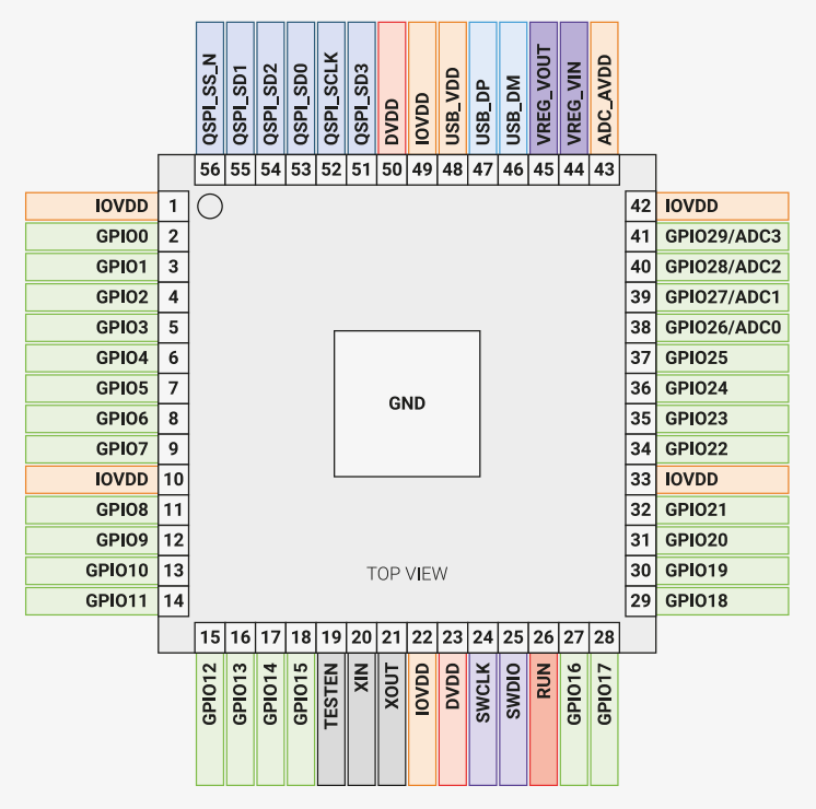
The image above shows the top view pin configuration of the RP2040 microcontroller. Each pin has a specific function such as GPIO, power, ground, ADC, SPI, I2C, and more. Understanding the pinout is important for correctly connecting components like buttons, OLED displays, sensors, and other peripherals.
1. GPIO Pins (General Purpose Input/Output)
GPIO pins are the most commonly used pins in microcontroller projects. They can be configured as:
- Digital Input (for buttons, sensors)
- Digital Output (for LEDs, buzzers)
- Communication Pins (I2C, SPI, UART)
In the diagram, GPIO pins are labeled as:
- GPIO0 – GPIO29
For example:
- GPIO2 → Can be used as digital pin D2
- GPIO26–GPIO29 → Can also function as ADC inputs
2. Power Pins
Power pins provide voltage to the microcontroller.
- IOVDD – I/O voltage supply
- DVDD – Digital core voltage
- USB_VDD – USB power supply
- ADC_AVDD – Analog voltage supply
These pins should not be used as normal GPIO pins.
3. Ground (GND)
The large center pad labeled GND is the ground connection. All external components must share a common ground with the microcontroller.
4. ADC Pins (Analog Input)
The following pins support analog input:
- GPIO26 (ADC0)
- GPIO27 (ADC1)
- GPIO28 (ADC2)
- GPIO29 (ADC3)
These pins can read analog voltages (for sensors like temperature, light, potentiometers).
5. Communication Pins
I2C Communication
Used for devices like OLED displays. SDA and SCL lines are mapped to specific GPIO pins depending on configuration.
SPI Communication
Pins labeled SPI_SCLK, SPI_SD0, SPI_SD1, SPI_SS_N are used for SPI communication.
SWD (Debugging)
- SWCLK
- SWDIO
These are used for programming and debugging the microcontroller.
6. Using GPIO2 for Button Example
If using a push button connected to GPIO2:
- Connect one side of the button to GPIO2
- Connect the other side to GND
- Use
pinMode(GPIO2, INPUT_PULLUP);
When using INPUT_PULLUP:
- Button not pressed → HIGH
- Button pressed → LOW
7. Important Notes
- Always verify the board pin mapping (GPIO vs D-number).
- Never connect 5V directly to GPIO pins (RP2040 is 3.3V logic).
- Always connect GND of external devices to board GND.
Summary
The RP2040 microcontroller provides flexible GPIO pins that can function as digital input/output, analog input, or communication interfaces. Understanding the pinout ensures correct hardware connections and prevents damage to the board.
Key features
- Dual Arm Cortex-M0+ @ 133 MHz
- 264 kB on-chip SRAM in six independent banks
- Support for up to 16 MB of off-chip Flash via dedicated QSPI bus
- DMA controller
- Fully-connected AHB crossbar
- Interpolator and integer divider peripherals
- On-chip programmable LDO to generate core voltage
- 2 on-chip PLLs for USB and core clocks
- 30 GPIO pins (4 can be used as analogue inputs)
Peripherals
- 2 UARTs
- 2 SPI controllers
- 2 I2C controllers
- 16 PWM channels
- USB 1.1 controller & PHY (host and device support)
- 8 PIO state machines
One of my doubts was, how and why can I use Arduino on a Rasberry Pi board?
Here's what I learned:
Your XIAO RP2040 uses the RP2040 chip made by Raspberry Pi, but it's a microcontroller board (like an Arduino), NOT a Raspberry Pi computer.
Arduino isn't just hardware - it's also:
- A programming language (based on C++)
- A development environment (Arduino IDE)
- A set of libraries that make programming easier
Arduino IDE can program many different microcontroller chips, including:
- ATmega (original Arduino)
- ESP32 (WiFi boards)
- SAMD (Arduino Zero, MKR boards)
- RP2040 (Raspberry Pi chips)
Prerequisites
To get started, ensure you have:
- An RP2040 board
- The Arduino IDE
- A USB cable
Setting Up the Software
Install the Arduino IDE
Download and install the latest Arduino IDE from the official site: Arduino Software.
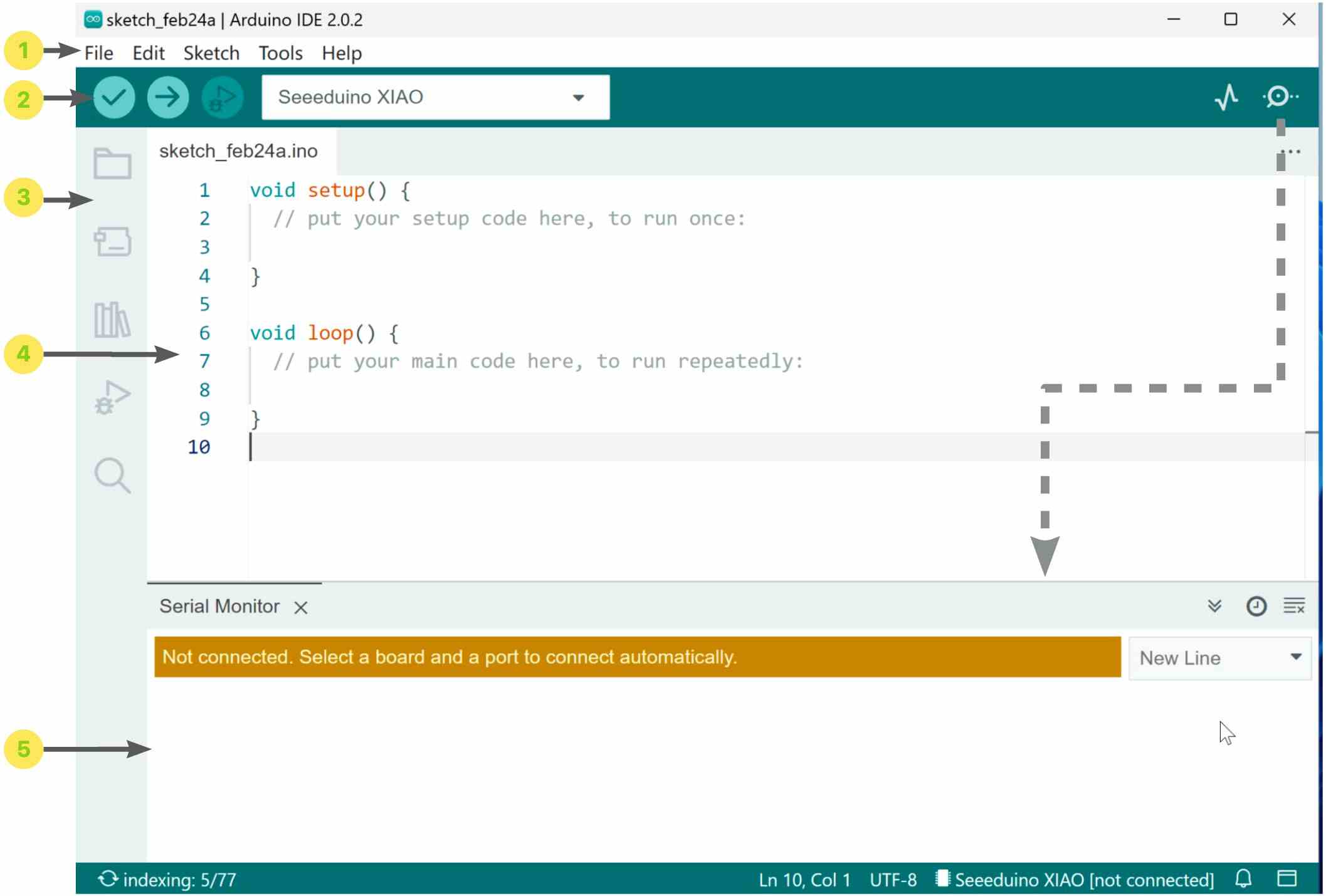
Arduino IDE Interface Overview
-
Menu Bar
The Menu Bar contains the main control options for the Arduino IDE. It includes menus such as File, Edit, Sketch, Tools, and Help.
- Create new sketches
- Open and save files
- Access example programs
- Select board type
- Select serial port
- Configure preferences
-
Horizontal Toolbar
The horizontal toolbar provides quick access to commonly used functions.
- Verify – Compiles the code to check for errors.
- Upload – Uploads the program to the connected board.
- Debug – Starts debugging (if supported).
- Board Selection – Displays and selects the active board.
- Serial Plotter – Opens the serial data graph window.
- Serial Monitor – Opens the serial communication window.
-
Vertical Toolbar
The vertical toolbar provides shortcuts for project management and development tools.
- Project Folder – View and manage sketch files.
- Board Manager – Install and manage board packages.
- Library Manager – Install and manage libraries.
- Debug – Access debugging tools.
- Search – Search within the code.
-
Code Editing Area
The code editing area is where program code is written and modified. It functions like a standard text editor, similar to typing in a word processor. All sketch files are written in this area.
-
Serial Monitor and Output Window
The Serial Monitor and output window allow communication between the computer and the microcontroller.
- The Serial Monitor displays data sent from the board.
- It can also send data to the board.
- The output window shows compilation messages and errors.
The Serial Monitor can be opened or closed using the button located on the right side of the horizontal toolbar.
Add RP2040 Board Support
Open the Arduino IDE and navigate to File > Preferences.
In the Additional Boards Manager URLs field, add this URL:
https://github.com/earlephilhower/arduino-pico/releases/download/global/package_rp2040_index.json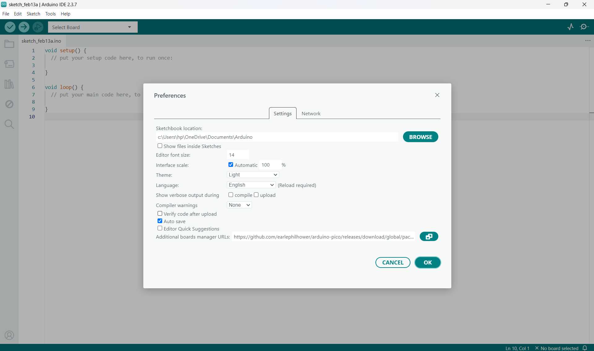
Click OK to save your settings.
Go to Tools > Board > Boards Manager.
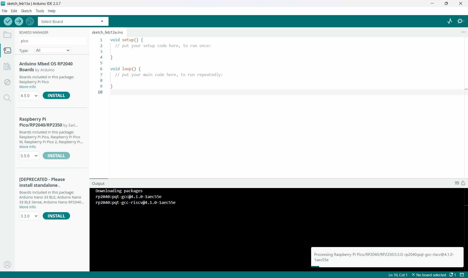
In the Boards Manager, search for pico and click Install.
After installation, go to Tools > Board and select the board shown below as your board.
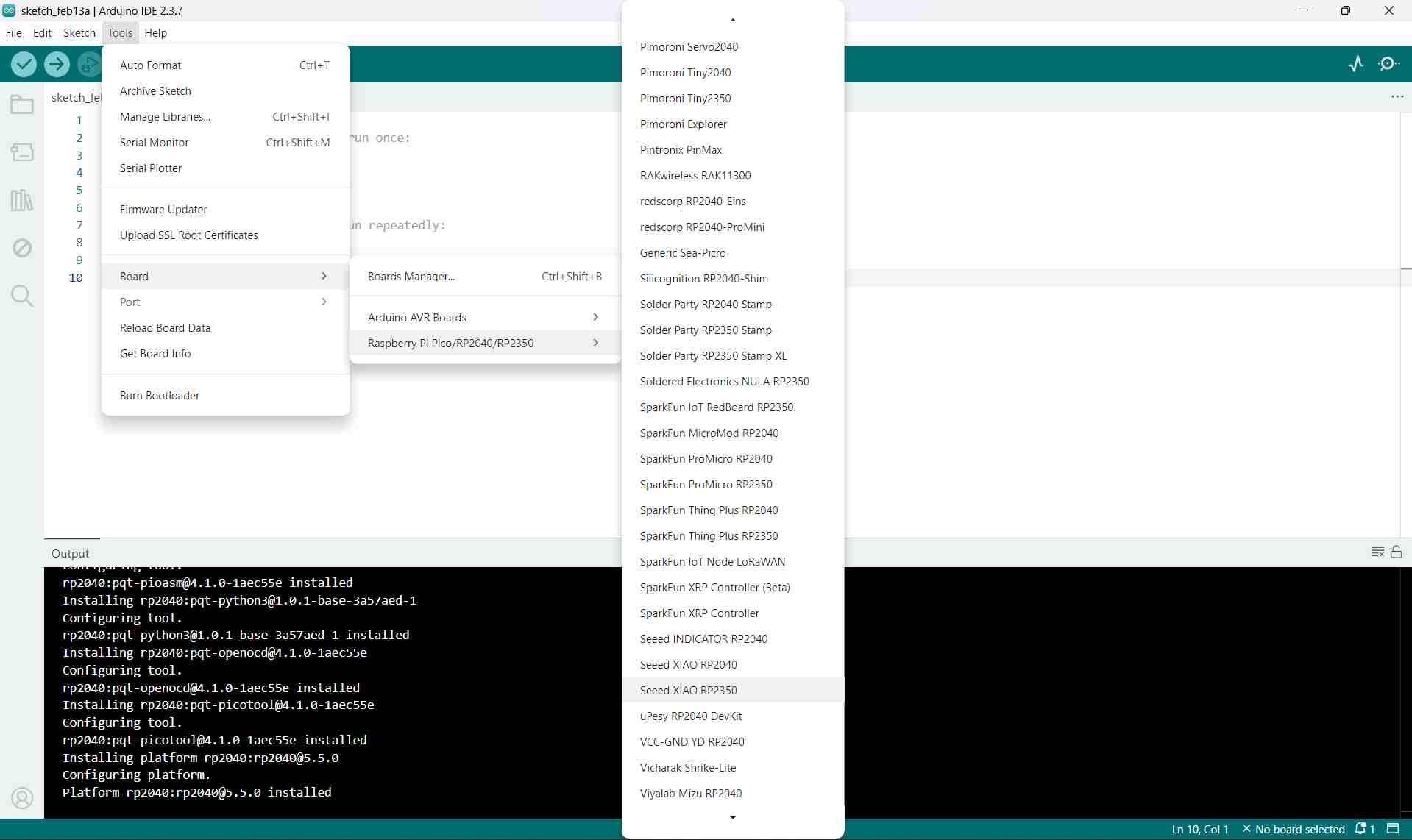
Note:
 Ensure you install version 4.2.0 or later for full support of the XIAO RP2040 board.
What is a Board Manager?
Board Manager is like an app store for microcontroller boards inside Arduino IDE.
Why Do We Need It?
Arduino IDE doesn't come with support for every microcontroller board in the world pre-installed. That would make it huge and slow! Instead, it comes with just the basic Arduino boards (like Uno, Mega).
When you want to program a different board (like your XIAO RP2040), you need to download and install the support package for that specific chip/board family.
What Does a Board Package Include?
When you install a board package (like "Raspberry Pi Pico/RP2030"), you get:
- Compiler - Converts your Arduino code into machine code for that specific chip
- Pin definitions - Tells Arduino IDE which pins are which (D0, D1, A0, etc.)
- Libraries - Special functions that work with that chip's hardware (WiFi, USB, etc.)
- Upload tools - Software to transfer your program to the board
- Board configuration - Settings specific to different boards using the same chip
Entering BOOT Mode on the XIAO RP2040
To place your XIAO RP2040 into BOOT mode, use one of the methods below:
Method 1: Before Connecting to Computer
Use this when your board is NOT plugged in yet
- Locate the BOOT button on your XIAO RP2040 (small button, often labeled "B" or "BOOT")
- Press and HOLD the BOOT button with your finger
- While still holding BOOT, plug the USB-C cable into your board
- Keep holding BOOT for about 2 seconds after plugging in
- Release the BOOT button
If the process is successful, your computer will make the USB connection sound and a new drive will appear, similar to a USB flash drive. The drive is typically named "RPI-RP2" or something similar. This indicates that the board has successfully entered BOOT mode and is ready to receive a program.
This method is recommended when programming the board for the first time, when the board is currently unplugged, or when you want the simplest way to start fresh.
Method 2: While Connected to Computer
Use this when your board is ALREADY plugged in
- Your XIAO RP2040 is already connected via USB
- Press and HOLD the BOOT button
- While holding BOOT, do ONE of these:
- Option A: Press and release the RESET button (if your board has one)
- Option B: Unplug and replug the USB cable
- Release the BOOT button
When the procedure is successful, the board will restart while entering BOOT mode. A new drive will appear on your computer, similar to a USB flash drive. This indicates that the board is now ready to receive a program.
This method is useful when the board is already plugged into the computer, when you need to re-enter BOOT mode, or when an upload has failed and you need to try again.
Visual Comparison:
- Method 1:
- Unplugged → Hold BOOT → Plug USB → Wait 2 sec → Release BOOT
- Method 2:
- Already plugged in → Hold BOOT → Press RESET (or unplug/replug) → Release BOOT
You can see a power LED turn on when you connect your PC to the board via USB.
- Open the Arduino IDE and create a new sketch.
Arduino Program Structure
Every Arduino sketch (program) has two main functions that are required.
1. void setup()
void setup() {// Runs ONCE when the board starts}
The setup() function runs only once, either when you power on the board
or press the reset button. It is primarily used for initialization, setting up
components and configurations before the main program starts.
Common tasks performed in setup() include:
Setting pin modes as input or output, starting serial communication, initializing sensors or displays, and assigning initial values to variables.
2. void loop()
void loop() { // Runs OVER and OVER forever}What it does:
- Runs continuously after
setup()finishes - Repeats forever in a loop: runs → finishes → runs again ...
- This is where your main program logic goes
Common things you put in loop():
- Read sensors
- Turn LEDs on/off
- Check button presses
- Send/receive data
- Make decisions based on inputs
Official Reference
For complete documentation on Arduino functions and syntax, visit the Official Arduino Language Reference.
Here's some things I learned during the week
Arduino Code Examples
Explore practical code examples that demonstrate the fundamentals of programming the XIAO RP2040 board. These examples cover everything from basic LED control to more advanced sensor interaction.
- Blinking LED patterns
- Button input handling
- PWM for dimming and motor control
- Serial communication
- Sensor reading and data processing
Start with simple examples and gradually explore more complex projects as you build confidence with the platform.
View Arduino Code ExamplesXIAO RP2040 Pin Guide
Understanding the pin configuration of your XIAO RP2040 is essential for hardware projects. This guide provides detailed information about each pin's capabilities and how to use them effectively.
- GPIO pin assignments and functions
- Analog input pin configuration
- PWM-capable pins
- I2C and SPI pin mapping
- UART and communication pins
- Power and ground pin locations
Reference this guide whenever you're connecting sensors or external components to ensure proper pin usage.
View Pin Configuration GuideRunning the Blink Program on the Seeed Studio XIAO
In embedded programming, the “Blink” example is similar to the classic “Hello World” program in other programming languages. It is usually the first program uploaded to a microcontroller to verify that the board is functioning correctly.
In this task, I used the built-in Blink example from the Arduino IDE to make the onboard LED of the Seeed Studio XIAO board flash.
Opening the Blink Example
To access the example code in the Arduino IDE:
- Go to File → Examples → 01.Basics → Blink
This opens the official Blink program provided by Arduino. The syntax highlighting (different colors for keywords and functions) confirms that the code is written correctly. It is important to pay attention to uppercase and lowercase letters, as Arduino is case-sensitive.
Blink Program Code
                    // the setup function runs once when you press reset or power the board
                    void setup() {
                    // initialize digital pin LED_BUILTIN as an output.
                        pinMode(LED_BUILTIN, OUTPUT);
                    }

                    // the loop function runs repeatedly
                    void loop() {
                        digitalWrite(LED_BUILTIN, HIGH);  // turn the LED on
                        delay(1000);                      // wait for 1 second
                        digitalWrite(LED_BUILTIN, LOW);   // turn the LED off
                        delay(1000);                      // wait for 1 second
                    }
Understanding the Code
1. setup() Function
The setup() function runs only once when the board is powered on or reset.
pinMode(LED_BUILTIN, OUTPUT);LED_BUILTINrefers to the onboard LED pin of the selected board.OUTPUTconfigures that pin as an output so it can control the LED.
2. loop() Function
The loop() function runs continuously in an infinite loop.
digitalWrite(LED_BUILTIN, HIGH);Sets the LED pin to HIGH (turns the LED ON).
delay(1000);Waits for 1000 milliseconds (1 second).
digitalWrite(LED_BUILTIN, LOW);Sets the LED pin to LOW (turns the LED OFF).
Another delay(1000); keeps the LED off for 1 second before the cycle repeats.
After writing the code:
- Click the "Verify" button in the Arduino IDE to check for errors in your code.
- Click the "Upload" button to send the program to your board.
Result
After uploading the code to the XIAO board:
- The onboard LED turns ON for 1 second.
- The LED turns OFF for 1 second.
- This cycle repeats continuously.
This confirms that the board is properly connected, the correct board and port are selected, and the Arduino IDE is working correctly. The Blink program serves as a basic hardware test and marks the first successful step in embedded programming.
PROGRAM FILEBlinking an External LED
After successfully testing the onboard LED using the Blink example, I connected an external LED to the XIAO RP2040 and programmed it to blink. This helped me understand GPIO pin control and basic circuit connections.
Components Used
- Seeed Studio XIAO RP2040
- External LED
- 220Ω Resistor
- Breadboard
- Jumper wires
Circuit Connection
- Connect the longer leg (Anode) of the LED to a GPIO pin (e.g., D2).
- Connect the shorter leg (Cathode) to one end of a 220Ω resistor.
- Connect the other end of the resistor to GND.
The resistor is necessary to limit the current and protect the LED from burning out.
Arduino Code
                    const int ledPin = 2;  // GPIO pin connected to external LED

                    void setup() {
                        pinMode(ledPin, OUTPUT);  // Set the LED pin as output
                    }

                    void loop() {
                        digitalWrite(ledPin, HIGH);  // Turn LED ON
                        delay(1000);                 // Wait 1 second
                        digitalWrite(ledPin, LOW);   // Turn LED OFF
                        delay(1000);                 // Wait 1 second
                    }
Explanation
pinMode(ledPin, OUTPUT);sets the selected GPIO pin as an output.digitalWrite(ledPin, HIGH);sends 3.3V to the pin, turning the LED ON.digitalWrite(ledPin, LOW);sets the pin to 0V, turning the LED OFF.delay(1000);creates a 1-second delay between ON and OFF states.
Understanding the LED Connection
An LED (Light Emitting Diode) has two legs and must be connected in the correct direction to function properly.
LED Structure
- Anode (+) → Longer leg
- Cathode (−) → Shorter leg
Current flows from the anode to the cathode. If the LED is reversed, it will not light up.
Basic LED Wiring with RP2040
                        D0 ---- Resistor ---- Anode (+)
                        Cathode (−) --------- GND
- D0 connects to the LED through a resistor.
- The cathode connects directly to GND.
Why a Resistor Is Required
An LED cannot be connected directly to a microcontroller pin. Without a resistor:
- Excess current can flow.
- The LED can burn out.
- The microcontroller pin can be damaged.
The resistor limits current to a safe level. Common values include 220Ω, 330Ω, or 1kΩ.
How the LED Works in the Program
When the pin is set HIGH:
- Voltage flows from D0 through the resistor.
- Current passes through the LED to GND.
- The LED turns ON.
When the pin is set LOW:
- No voltage difference exists.
- No current flows.
- The LED turns OFF.
Breadboard Placement
- Place the two LED legs in different rows.
- Connect the resistor in series with one leg.
- Connect the other leg to GND.
Do not place both legs in the same connected row, as this will short the connection and the LED will not function correctly.
Result
After uploading the code, the external LED blinked at a 1-second interval. This confirmed that I was successfully controlling an external component using a GPIO pin of the XIAO RP2040.
PROGRAM FILEAirbus Blink
Inspired by the blinking pattern of Airbus aircraft navigation and beacon lights, I programmed the LED to blink in a custom pattern instead of a simple 1-second interval. Aircraft lights typically blink in quick bursts followed by a pause, creating a recognizable rhythm.
Objective
To simulate an aircraft-style blinking pattern using an external LED connected to the XIAO RP2040.
Arduino Code
                    const int ledPin = 2;  // GPIO pin connected to LED

                    void setup() {
                        pinMode(ledPin, OUTPUT);
                    }

                    void loop() {
                        // First quick flash
                        digitalWrite(ledPin, HIGH);
                        delay(100);
                        digitalWrite(ledPin, LOW);
                        delay(100);

                        // Second quick flash
                        digitalWrite(ledPin, HIGH);
                        delay(100);
                        digitalWrite(ledPin, LOW);
                        delay(1000);  // Longer pause before repeating
                    }
Pattern Explanation
- Two quick flashes (100ms ON, 100ms OFF)
- Followed by a longer pause (1000ms)
- The pattern repeats continuously
Result
The LED blinks in a rhythmic double-flash pattern similar to aircraft beacon lights.
This exercise helped me understand how timing control using delay()
can be used to create different signal patterns instead of a simple ON/OFF blink.
Demonstration
PROGRAM FILEXmas Lights
For this exercise, I created a Christmas lights style blinking pattern using multiple LEDs. Instead of a single LED blinking, I programmed alternating patterns to simulate festive decorative lighting effects.
Objective
To create a sequential and alternating LED pattern similar to decorative Christmas lights.
Components Used
- Seeed Studio XIAO RP2040
- 3 External LEDs
- 220Ω Resistors (one for each LED)
- Breadboard
- Jumper wires
Circuit Connections
- LED 1 → GPIO 2
- LED 2 → GPIO 3
- LED 3 → GPIO 4
- All cathodes connected to GND through resistors
Arduino Code
                    int Delay = 1000;
                    void setup() {
                        // initialize digital pin LED_BUILTIN as an output.
                        pinMode(D0, OUTPUT);
                        pinMode(D1, OUTPUT);
                        pinMode(D2, OUTPUT);
                        pinMode(D3, OUTPUT);
                        pinMode(D4, OUTPUT);
                    }

                    // the loop function runs over and over again forever
                    void loop() {
                        digitalWrite(D0, LOW);  // turn the LED on (LOW is the voltage level)
                        delay(Delay);
                        digitalWrite(D0, HIGH);            // wait for a second
                        digitalWrite(D1, LOW);
                        delay(Delay);
                        digitalWrite(D1, HIGH);
                        digitalWrite(D2, LOW);
                        delay(Delay);
                        digitalWrite(D2, HIGH);
                        digitalWrite(D3, LOW);
                        delay(Delay);
                        digitalWrite(D3, HIGH);
                        digitalWrite(D4, LOW);
                        delay(Delay);
                        digitalWrite(D4, HIGH);
                    }
Explanation
- Multiple LEDs are controlled using different GPIO pins.
- Each pattern changes which LEDs are ON or OFF.
delay()controls the speed of the light transitions.- The loop repeats continuously to simulate festive blinking lights.
Result
The LEDs blink in alternating and mixed patterns similar to decorative Christmas lights. This activity helped me understand how to control multiple GPIO outputs and create custom light sequences.
Demonstration
PROGRAM FILEInterfacing a Button with the RP2040
After successfully blinking an LED using the RP2040, the next step was to introduce user input using a push button. Unlike an LED (which is an output device), a button is an input device. This means the microcontroller must read its state and determine whether it is pressed or not.
What is a Button in a Circuit?
A button connects two points when you press it. When you do not press it, it disconnects them.
That is the basic working principle.
A microcontroller must clearly detect whether a pin is:
- HIGH (1)
- LOW (0)
When the button is not pressed and no additional components are used, the input pin is not connected to either HIGH or LOW. This condition is called a floating input.
What Happens Without Pull-Up or Pull-Down?
If no pull-up or pull-down resistor is used:
When you press the button:
- If the button connects the pin to Power (VCC) → it reads HIGH
- If the button connects the pin to Ground (GND) → it reads LOW
However, when you release the button, the pin is no longer connected to either HIGH or LOW. It becomes floating again and may read randomly.
A floating input is unstable because:
- It may randomly read 1
- It may randomly read 0
- The signal becomes unstable
- The program may behave unexpectedly
Pull-Up Resistor
A pull-up resistor connects the input pin to VCC (HIGH) through a resistor.
- Button NOT pressed → Pin reads HIGH
- Button pressed → Pin reads LOW (connected to GND)
The resistor pulls the pin up to HIGH when no other signal is applied, ensuring a stable default state.
Pull-Down Resistor
A pull-down resistor connects the input pin to GND (LOW) through a resistor.
- Button NOT pressed → Pin reads LOW
- Button pressed → Pin reads HIGH (connected to VCC)
The resistor pulls the pin down to LOW when the button is not pressed, ensuring a stable default state.
Why Pull-Up or Pull-Down Resistors Are Necessary
- Prevents floating inputs
- Ensures stable and predictable readings
- Provides a defined default state
- Protects the circuit by limiting current
Important Note
If power is directly connected to ground when the button is pressed without a resistor, it creates a short circuit.
A short circuit can damage the board. The resistor limits current and protects the microcontroller.
Summary
- Pull-up → Default state is HIGH
- Pull-down → Default state is LOW
- Prevents floating inputs
- Ensures stable button readings
- Protects the circuit
Using the Internal Pull-Up Resistor on the RP2040
Instead of adding an external pull-up or pull-down resistor on the breadboard, the RP2040 allows us to enable an internal pull-up resistor using software. This simplifies the wiring and reduces extra components.
Step 1: Define the Pins
First, assign the LED and button pins to variables for clarity.
                    int led = D0;
                    int button = D1;
Step 2: Configure Pin Modes
Inside the setup() function, configure the LED as OUTPUT and the button as INPUT_PULLUP.
                    void setup() {
                        pinMode(led, OUTPUT);
                        pinMode(button, INPUT_PULLUP);
                    }
Enabling INPUT_PULLUP activates the internal resistor inside the RP2040. This means:
- Button NOT pressed → Pin reads HIGH
- Button pressed → Pin reads LOW
The logic is inverted compared to a pull-down configuration. LOW now means the button is pressed.
Step 3: Read the Button State
In the loop() function, read the button state and store it in a variable.
                    void loop() {
                        int button_state = digitalRead(button);
                    }
Step 4: Control the LED
Since a pressed button reads LOW when using INPUT_PULLUP, the condition must check for LOW.
                    if (button_state == LOW){
                        digitalWrite(led, HIGH);
                    }
                    else {
                        digitalWrite(led, LOW);
                    }
Understanding the If–Else Condition
In this step, the program decides whether the LED should turn ON or OFF based on the value read from the button.
When using INPUT_PULLUP, the logic is inverted:
- Button pressed → LOW
- Button not pressed → HIGH
The program first reads the button state and stores it in the variable
button_state. Then it uses an if–else statement
to make a decision.
                    if (button_state == LOW){
                        digitalWrite(led, HIGH);
                    }
                    else {
                        digitalWrite(led, LOW);
                    }
Line-by-Line Explanation
-
if (button_state == LOW)
The program checks if the button is pressed. Since we are using INPUT_PULLUP, LOW means the button is pressed. -
digitalWrite(led, HIGH);
If the button is pressed, the LED pin is set to HIGH, which turns the LED ON. -
else
If the button is not pressed, the program runs the alternative block. -
digitalWrite(led, LOW);
The LED pin is set to LOW, which turns the LED OFF.
In simple terms, this code continuously checks the button. If the button is pressed, the LED turns ON. If the button is released, the LED turns OFF.
Wiring Configuration
- One side of the button → D1
- Other side of the button → GND
- No external resistor required
When the button is pressed, it connects the pin directly to GND, overriding the internal pull-up and causing the pin to read LOW.
Complete Program
                    int led = D0;
                    int button = D1;

                    void setup() {
                        pinMode(led, OUTPUT);
                        pinMode(button, INPUT_PULLUP);
                    }

                    void loop() {

                        int button_state = digitalRead(button);

                        if (button_state == LOW){
                            digitalWrite(led, HIGH);
                        }
                        else {
                            digitalWrite(led, LOW);
                        }

                    }
Understanding the 4-Leg Push Button
A standard tactile push button has four external legs, but internally it functions as a single switch. The four legs are arranged in two pairs.
Internal Connection of the Button
Inside the button:
- The two legs on one side are permanently connected together.
- The two legs on the opposite side are permanently connected together.
- Pressing the button connects both sides together.
Internally, it can be visualized as:
                    (leg1) —— —— —— (leg2)
                        |          |
                        |  SWITCH  |
                        |          |
                    (leg3) —— —— —— (leg4)
This means:
- Left pair of legs = connected
- Right pair of legs = connected
- Pressing the button connects left side to right side
How to Use the Button in the Circuit
Only one leg from each side should be used in the circuit.
- One leg from the first side → Connect to D1
- One leg from the opposite side → Connect to GND
Connecting two legs from the same side is unnecessary because they are already internally connected.
Common Wiring Mistake
If D1 and GND are connected to two legs on the same row (for example both on the top row), they are permanently connected.
This causes the input pin to always read LOW, making the LED stay ON continuously.
Correct Wiring with INPUT_PULLUP
- Connect one leg from the top row → D1
- Connect one leg from the bottom row → GND
- Place the button across the center gap of the breadboard
When not pressed:
- The internal pull-up resistor keeps D1 HIGH.
When pressed:
- The button connects D1 to GND.
- D1 reads LOW.
- The LED turns ON.
Testing Behavior
- Not pressed → Serial Monitor prints 1
- Pressed → Serial Monitor prints 0
Placing the Button on a Breadboard
How a Breadboard Is Wired Internally
- Each row of five holes is connected horizontally.
- The left and right sections are separated by a center gap.
- Rows on the left side are NOT connected to rows on the right side.
The center gap electrically separates the two halves of the breadboard.
Why the Button Must Cross the Center Gap
When the button is placed across the center gap:
- Two legs sit on the left side of the board.
- Two legs sit on the right side of the board.
- The two sides remain electrically separate until the button is pressed.
This allows the button to properly open and close the circuit.
What Happens If It Is Placed Incorrectly
If the button is placed entirely on one side of the breadboard:
- Both legs from one side may sit in the same connected row.
- They are already connected through the breadboard.
- Pressing the button will not change the circuit.
For correct operation, the button must straddle the center gap so that pressing it bridges two electrically separate rows.
Make the Electrical Connections
For an INPUT_PULLUP configuration:
- Connect one leg from the first side → D1 (button pin)
- Connect one leg from the opposite side → GND
When the button is pressed, it connects D1 directly to GND. When released, the pin remains HIGH due to the internal pull-up resistor.
Working Principle
When the button is pressed, it creates a connection between D1 and GND. Since the pin is configured with an internal pull-up resistor, its normal state is HIGH. Pressing the button forces it LOW.
The program detects this LOW signal and turns the LED ON. Releasing the button returns the pin to HIGH, turning the LED OFF.
PROGRAM FILEInterfacing a 0.96" I2C OLED Display with RP2040
Component Description
The display used is a 0.96" I2C OLED module (128 × 64 resolution), commonly based on the SSD1306 driver. The module communicates using the I2C protocol, which requires only two signal wires.
- Resolution: 128 × 64 pixels
- Communication Protocol: I2C
- Driver IC: SSD1306
- Operating Voltage: 3.3V
Pin Configuration
The OLED module has four pins:
                    GND   → Ground
                    VCC   → 3.3V Power
                    SCL   → I2C Clock Line
                    SDA   → I2C Data Line
Wiring Connections
The OLED was connected to the RP2040 board as follows:
                OLED        →    RP2040
                -----------------------------
                GND         →    GND
                VCC         →    3.3V
                SCL         →    SCL pin
                SDA         →    SDA pin
Only four wires are required due to I2C communication. No external resistors are needed for this module.
I2C Address
The module includes an address selection option labeled:
                    0x3C  (default)
                    0x3D  (alternative address)
In this setup, the default address 0x3C is used.
To learn more about I2C addresses and OLED modules, refer the link here.
SCL and SDA Pins on the Seeed XIAO RP2040
On the Seeed XIAO RP2040 board, the I2C pins are already labeled. You do not need to guess them.
I2C Default Pins
- SDA → D4
- SCL → D5
So when connecting your OLED:
- OLED SDA connects to D4
- OLED SCL connects to D5
What Do These Pins Do?
- SDA (D4) carries the data.
- SCL (D5) provides the clock signal (timing).
Complete Wiring for XIAO RP2040
- OLED GND → XIAO GND
- OLED VCC → XIAO 3.3V
- OLED SDA → XIAO D4
- OLED SCL → XIAO D5
Only four wires are needed because I2C uses just two communication lines.
Library Installation
To control the OLED, the following libraries were installed using Arduino Library Manager:
- Adafruit SSD1306
- Adafruit GFX
Step 1: Open the Library Manager
First, open the Arduino IDE on your computer.
At the top of the window, you will see a menu bar.
Click on:
Sketch → Include Library → Manage Libraries...This will open the Library Manager.
What is the Library Manager?
The Library Manager is where you can search for and install extra libraries. Libraries are collections of pre-written code that help you control hardware easily — like OLED displays.
In the search bar of the Library Manager, type:
U8G2Find the library named U8g2 by oliver.
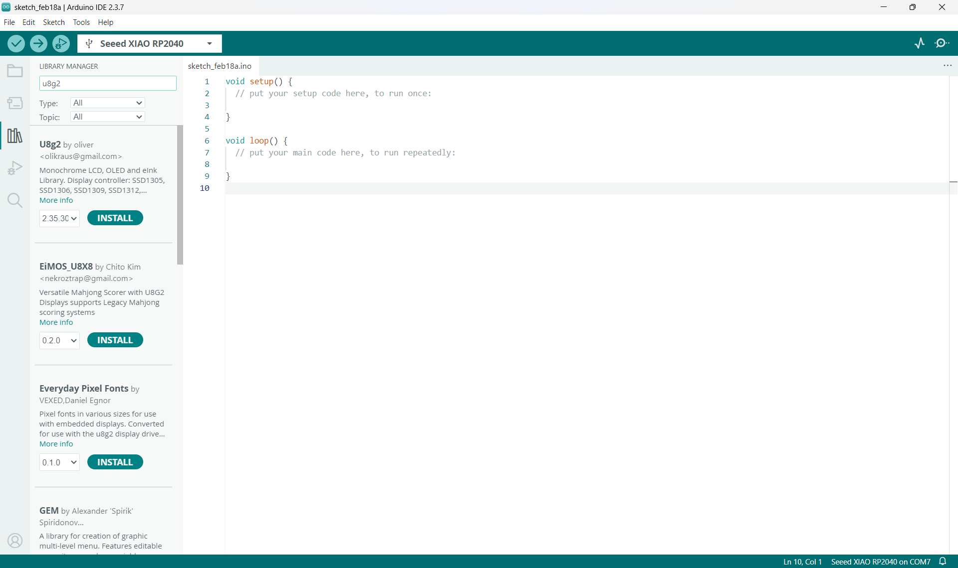
Click Install and make sure you install the latest version.
Step 2: Upload the Example Code
1. Copy the code below.
2. Paste it into a new Arduino sketch.
3. Click the Upload button to upload the program to your board.
                #include <Arduino.h>
                #include <U8g2lib.h>
                #include <Wire.h>

                // Use Hardware I2C
                U8G2_SSD1306_128X64_NONAME_F_HW_I2C u8g2(U8G2_R0, U8X8_PIN_NONE);

                void setup() {
                    u8g2.begin();
                }

                void loop() {
                    u8g2.clearBuffer();
                    u8g2.setFont(u8g2_font_ncenB08_tr);
                    u8g2.drawStr(0, 20, "Hello Guyzz!");
                    u8g2.drawStr(0, 40, "It's Merin!");
                    u8g2.sendBuffer();
                    delay(1000);
                }
Code Explanation
Including Libraries
                #include <Arduino.h>
                #include <U8g2lib.h>
                #include <Wire.h>
These lines add special libraries (tools) to our project.
- Arduino.h → Basic Arduino functions
- U8g2lib.h → Library to control the OLED display
- Wire.h → Allows communication using I2C
Creating the OLED Object
U8G2_SSD1306_128X64_NONAME_F_HW_I2C u8g2(U8G2_R0, U8X8_PIN_NONE);
This line creates an OLED display object named u8g2.
- SSD1306 → OLED controller type
- 128X64 → Screen resolution
- HW_I2C → Uses hardware I2C communication
Setup Function
                void setup() {
                    u8g2.begin();
                }
The setup() function runs only once when the Arduino starts.
u8g2.begin(); initializes (starts) the OLED display.
Loop Function
                void loop() {
                    u8g2.clearBuffer();
                    u8g2.setFont(u8g2_font_ncenB08_tr);
                    u8g2.drawStr(0, 20, "Hello Guyzz!");
                    u8g2.drawStr(0, 40, "It's Merin!");
                    u8g2.sendBuffer();
                    delay(1000);
                }
The loop() function runs again and again forever.
Explanation of Each Line:
- clearBuffer() → Clears the screen before writing new text
- setFont() → Sets the font style for the text
- drawStr(x, y, text) → Displays text at position (x, y)
- sendBuffer() → Sends all text to the OLED screen
- delay(1000) → Waits for 1 second
How the Program Works
- Arduino starts
- OLED initializes
- Screen clears
- Text is written
- Text appears on screen
- Wait 1 second
- Repeat forever
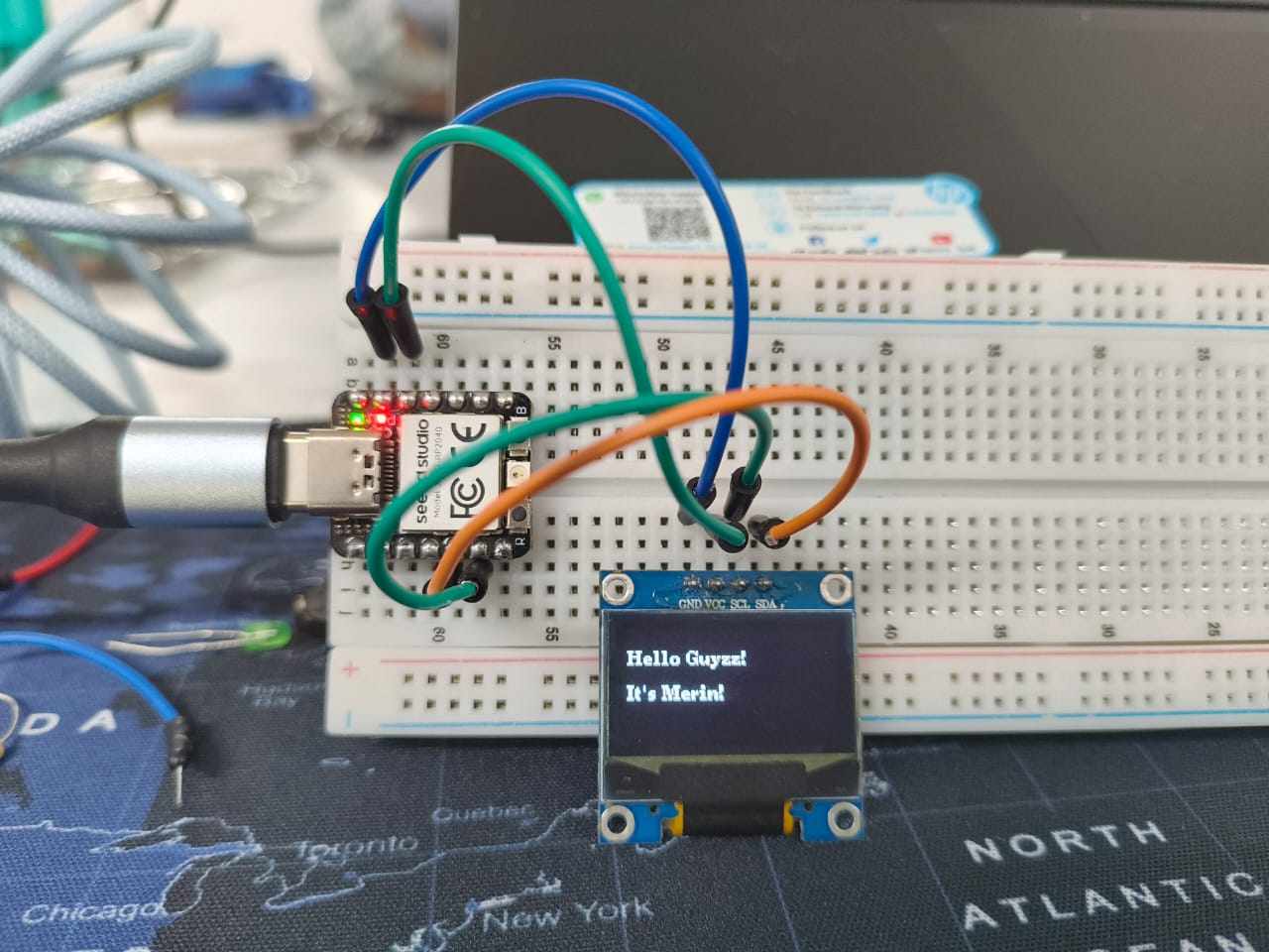
Final Output
The OLED screen displays:
Hello Guyzz!
It's Merin!
 PROGRAM FILE
SEED STUDIO XIAO NRF52840
Introduction
After working with the RP2040 board, I explored another microcontroller: the Seeed Studio XIAO nRF52840.
This board is compact, low-power, and includes built-in Bluetooth Low Energy (BLE). It is suitable for wireless and battery-powered embedded projects.
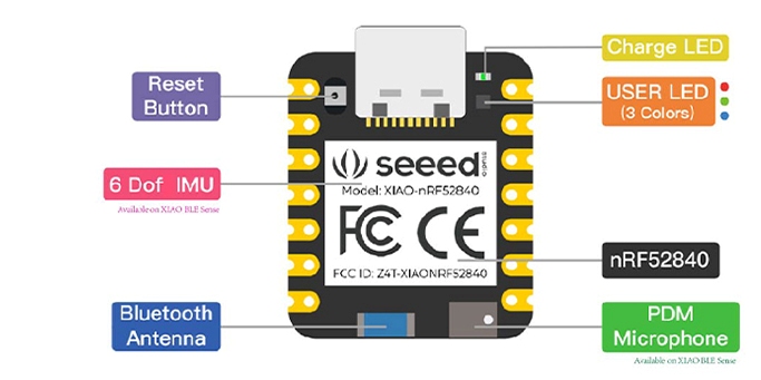
Microcontroller Overview
The XIAO nRF52840 is based on the Nordic nRF52840 chip.
- 32-bit ARM Cortex-M4 processor
- Built-in Bluetooth Low Energy (BLE)
- Low power consumption
- Supports I2C, SPI, and UART communication
- USB-C interface for programming
Why Use nRF52840 Instead of RP2040?
- Built-in wireless capability (BLE)
- Better for portable battery projects
- Integrated LiPo battery charging circuit
- Very small and compact form factor
Unlike the RP2040, this board supports wireless communication without requiring additional modules.
Power Options
The XIAO nRF52840 can be powered in two ways:
- USB-C connection
- 3.7V LiPo battery (via onboard battery connector)
The board includes a built-in charging circuit, so no external charging module such as TP4056 is required.
Installing Board Support in Arduino IDE
To program the XIAO nRF52840 using Arduino IDE, board support must be installed.
Step 1: Open Preferences
Go to:
File → PreferencesStep 2: Add Board Manager URL
In the "Additional Boards Manager URLs" field, add:
https://files.seeedstudio.com/arduino/package_seeeduino_boards_index.jsonClick OK.
Step 3: Install the Board Package
Go to:
Tools → Board → Boards ManagerSearch for:
Seeed nRF52 BoardsClick Install.
Step 4: Select the Board
After installation, go to:
Tools → BoardSelect:
Seeed XIAO nRF52840Bootloader Mode (Uploading Program)
To upload code to the XIAO nRF52840, the board must enter bootloader mode.
Method 1: Double-Press Reset Button
The easiest way to enter bootloader mode is by double-pressing the reset button.
- Connect the board to the computer using USB-C.
- Quickly press the reset button twice.
If done correctly:
- The onboard LED will start slowly pulsing.
- A new USB drive will appear on the computer.
This indicates that the board has entered bootloader mode and is ready to receive new firmware.
Method 2: If Upload Fails
Sometimes the upload may fail if the board is not in bootloader mode.
In that case:
- Press the reset button twice again.
- Select the new COM port that appears.
- Upload the code again.
Important Notes
- Single press = normal reset
- Double press = bootloader mode
- LED pulsing = bootloader active
Entering bootloader mode is necessary especially when switching between different firmware or when the board becomes unresponsive.
Installing CircuitPython on Seeed XIAO nRF52840
1 Download CircuitPython Firmware
Go to the official CircuitPython website:
https://circuitpython.org
Search for:
Seeed XIAO nRF52840
Download the latest stable .UF2 firmware file for:
Seeed XIAO nRF52840
(Make sure it is not the Sense version unless you are using that board.)
2 Put the Board into Bootloader Mode
Connect the Seeed XIAO nRF52840 to your PC using a USB cable.
Quickly press the RESET button twice.
The board will appear on your computer as a USB drive named:
XIAO-BOOT
If it does not appear:
- Try pressing reset twice again.
- Make sure you are using a data USB cable (not charge-only).
3 Install CircuitPython Firmware
Drag and drop the downloaded .uf2 file into the XIAO-BOOT drive.
The board will automatically reboot.
After reboot, a new drive will appear named:
CIRCUITPYThis confirms that CircuitPython is successfully installed.
Installing and Configuring Thonny
1 Install Thonny
Download Thonny from : https://thonny.org
Install it normally.
Launch Thonny.
2 Configure Thonny for CircuitPython
Open Thonny.
Go to:
Tools → Options → InterpreterSet:
- Interpreter: CircuitPython (generic)
- Select the correct COM port (the one that appears when the board is connected).
Click OK.
If configured correctly:
- You should see CIRCUITPY in the file browser.
- The shell should connect without errors.
Understanding the CIRCUITPY Drive
After installing CircuitPython:
The board behaves like a USB flash drive.
Inside CIRCUITPY, you will see:
            code.py
            lib/
            boot_out.txt
- code.py → Main program file (runs automatically)
- lib/ → Library folder
- boot_out.txt → Firmware info
Every time you save code.py, the board automatically runs it.
Blink Test Using Thonny
This test verifies that:
- CircuitPython is installed correctly
- Thonny is connected properly
- The board can execute Python code
1 Create the Blink Program
In Thonny:
- Click File → New
- Copy and paste the following code:
            import time
            import board
            import digitalio

            led = digitalio.DigitalInOut(board.LED)
            led.direction = digitalio.Direction.OUTPUT

            while True:
                led.value = True
                time.sleep(0.5)
                led.value = False
                time.sleep(0.5)
2 Save the File
- Click File → Save As
- Select: CircuitPython device
- Save the file as:
code.py⚠ Important: It must be named code.py.
3 Expected Result
- The onboard LED should start blinking.
- The LED turns ON for 0.5 seconds.
- The LED turns OFF for 0.5 seconds.
- This repeats continuously.
If it blinks → setup is successful.
What Happens Internally
When code.py is saved:
- The file is written to the CIRCUITPY drive.
- The board automatically restarts.
- CircuitPython executes
code.py. - The microcontroller:
- Configures the LED pin as output
- Alternates voltage HIGH/LOW
- Creates delay using
time.sleep()
Troubleshooting
Problem: CIRCUITPY drive not visible
- Double press reset.
- Reinstall firmware.
- Try different USB cable.
Problem: Thonny not connecting
- Check correct COM port.
- Select “CircuitPython (generic)” interpreter.
Problem: LED not blinking
- Ensure file name is
code.py - Confirm you are using
board.LED - Check shell for errors
Final Outcome
- ✔ CircuitPython successfully installed
- ✔ Thonny configured
- ✔ Board connected properly
- ✔ Blink test executed successfully
- ✔ Board ready for further development
You can download all the program files of this week from here.