XIAO RP2040 Complete Pin Guide
Your XIAO RP2040 is a tiny board with 14 GPIO pins total:
- 11 pins accessible via headers on the sides
- Some special pins on the bottom (via solder pads)
What is GPIO?
GPIO = General Purpose Input/Output
It means the pins can be programmed to do different things depending on what you need:
Input Mode:
The pin reads signals coming IN
- Read a button press (is it pressed or not?)
- Read a sensor (temperature, light, motion)
- Receive data from other devices
Output Mode:
The pin sends signals OUT
- Turn an LED on/off
- Control a motor
- Send data to displays or other devices
"General Purpose" means:
You choose what each pin does in your code! The same pin can be:
- An LED output today
- A button input tomorrow
- A sensor reader next week
Let me break down what each pin can do:
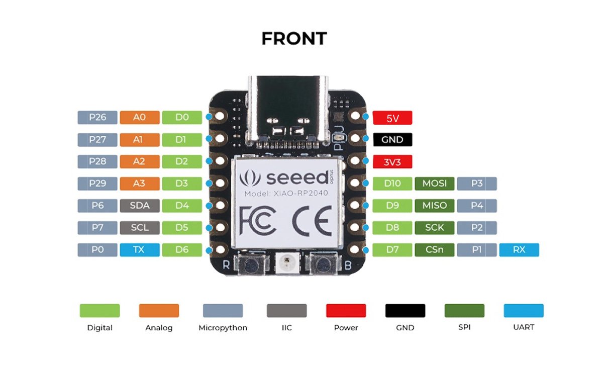
TOP SIDE PINS (Main Headers)
Left Side (7 pins)
D0 (A0) - GPIO 26 - Digital/Analog/PWM
D1 (A1) - GPIO 27 - Digital/Analog/PWM
D2 (A2) - GPIO 28 - Digital/Analog/PWM
D3 (A3) - GPIO 29 - Digital/Analog/PWM
D4 (SDA) - GPIO 6 - Digital/PWM/I2C Data
D5 (SCL) - GPIO 7 - Digital/PWM/I2C Clock
D6 (TX) - GPIO 0 - Digital/PWM/UART TX
Right Side (7 pins)
D7 (RX) - GPIO 1 - Digital/PWM/UART RX
D8 (SCK) - GPIO 2 - Digital/PWM/SPI Clock
D9 (MISO) - GPIO 4 - Digital/PWM/SPI
D10 (MOSI) - GPIO 3 - Digital/PWM/SPI
3V3 - 3.3V Power Output
GND - Ground
5V - 5V Power (from USB)
Digital pins (marked with D):
- Can only read two states: HIGH (on/5V) or LOW (off/0V)
- Used for: buttons, LEDs, on/off sensors
Analog pins (marked with A):
- Can read a range of voltages, typically 0V to 3.3V or 5V
- The built-in ADC (Analog-to-Digital Converter) converts the voltage to a number (usually 0-1023 on Arduino, 0-4095 on ESP32)
- Used for: potentiometers, temperature sensors, light sensors, joysticks, anything that gives variable voltage
Important note: Analog pins can also be used as digital pins, but digital pins usually cannot be used as analog inputs (though some boards have multiple analog-capable pins that aren't all marked with A).
TOP SIDE PINS (Main Headers)
Left Side (7 pins)
D0 (A0) - GPIO 26 - Digital/Analog/PWM
- Digital Input: Read buttons, sensors (HIGH/LOW)
- Digital Output: Control LEDs, relays
- Analog Input (A0): Read voltages 0-3.3V (potentiometers, light sensors, temperature)
- PWM Output: Fade LEDs, control motor speed
- Special power: One of only 4 analog-capable pins!
D1 (A1) - GPIO 27 - Digital/Analog/PWM
- Digital Input: Read buttons, sensors (HIGH/LOW)
- Digital Output: Control LEDs, relays
- Analog Input (A1): Read voltages 0-3.3V
- PWM Output: Fade LEDs, control motor speed
- Special power: Analog input - measure variable voltages!
D2 (A2) - GPIO 28 - Digital/Analog/PWM
- Digital Input: Read buttons, sensors (HIGH/LOW)
- Digital Output: Control LEDs, relays
- Analog Input (A2): Read voltages 0-3.3V
- PWM Output: Fade LEDs, control motor speed
- Special power: Analog input capability!
D3 (A3) - GPIO 29 - Digital/Analog/PWM
- Digital Input: Read buttons, sensors (HIGH/LOW)
- Digital Output: Control LEDs, relays
- Analog Input (A3): Read voltages 0-3.3V
- PWM Output: Fade LEDs, control motor speed
- Special power: Last analog pin!
D4 - GPIO 6 - Digital/PWM
- Digital Input: Read buttons, sensors
- Digital Output: Control LEDs, relays
- PWM Output: Fade LEDs, control servos
- I2C SDA: Can be used for I2C data line
D5 - GPIO 7 - Digital/PWM
- Digital Input: Read buttons, sensors
- Digital Output: Control LEDs, relays
- PWM Output: Fade LEDs, control servos
- I2C SCL: Can be used for I2C clock line
D6 (TX) - GPIO 0 - Digital/PWM/UART TX
- Digital Input: Read buttons, sensors
- Digital Output: Control LEDs, relays
- UART TX (Transmit): Send serial data to GPS, Bluetooth, other boards
- PWM Output: Fade LEDs, control servos
- Special power: Serial transmit - send data!
Right Side (7 pins)
D7 (RX) - GPIO 1 - Digital/PWM/UART RX
- Digital Input: Read buttons, sensors, receive UART data
- Digital Output: Control LEDs, relays
- UART RX (Receive): Receive serial data from other devices
- PWM Output: Fade LEDs, control servos
- SPI CS: Can be used as SPI chip select
- Special power: Serial receive - get data from other devices!
D8 (SCK) - GPIO 2 - Digital/PWM/SPI SCK
- Digital Input: Read buttons, sensors
- Digital Output: Control LEDs, relays
- SPI SCK (Clock): Timing signal for fast SPI communication
- PWM Output: Fade LEDs, control servos
- Special power: SPI clock - super fast for SD cards and displays!
D9 (MISO) - GPIO 4 - Digital/PWM/SPI MISO
- Digital Input: Read buttons, sensors, receive SPI data
- Digital Output: Control LEDs, relays
- SPI MISO (Main In Secondary Out): Receive data from SPI devices
- PWM Output: Fade LEDs, control servos
- Special power: SPI data input - get data from SD cards!
D10 (MOSI) - GPIO 3 - Digital/PWM/SPI MOSI
- Digital Input: Read buttons, sensors
- Digital Output: Control LEDs, relays, send SPI data
- SPI MOSI (Main Out Secondary In): Send data to SPI devices
- PWM Output: Fade LEDs, control servos
- Special power: SPI data output - send to displays, SD cards!
3V3 - 3.3V Power Output
- Clean regulated 3.3V (max 500mA)
- Powers your 3.3V sensors and modules
- Use for: OLED displays, sensors, small modules
GND - Ground
- The 0V reference point
- Always connect when wiring components
- Completes the circuit
5V - 5V Power (from USB)
- Available when USB is connected
- Can power 5V devices like servos
- Can also be used to power the board (input)
CRITICAL SAFETY WARNING
3.3V LOGIC ONLY!
- All GPIO pins work at 3.3V maximum
- Connecting 5V to any GPIO pin = PERMANENT DAMAGE
- The chip runs on 3.3V internally
Safe to connect:
- 3.3V sensors and modules
- Buttons (to GND)
- LEDs (with resistors)
DANGER - Will destroy the board:
- 5V Arduino sensors (without level shifter)
- 5V logic signals
- Any voltage above 3.3V on GPIO pins
BOTTOM SIDE PINS (Solder Pads)
These are under the board and need to be soldered to access:
SWCLK - Debug Clock Pin
SWDIO - Debug Data Pin
RESET (RUN) - Reset Pin
BOOT - Bootloader Mode Pin
GPIO 16 - RGB LED Green
GPIO 17 - RGB LED Red
GPIO 25 - RGB LED Blue
SWCLK - Debug Clock Pin
- Used for SWD (Serial Wire Debug) programming
- Connect to debugger for advanced programming
- 2.54mm spacing (standard breadboard spacing)
SWDIO - Debug Data Pin
- Used for SWD (Serial Wire Debug) programming
- Transfers data during debugging
- Works with Raspberry Pi Debug Probe or similar tools
RESET (RUN) - Reset Pin
- Pull LOW to reset the board
- Can be soldered for external reset button
- Same function as the onboard reset button
BOOT - Bootloader Mode Pin
- Pull LOW during power-up to enter bootloader
- Board appears as USB drive (RPI-RP2)
- Useful for firmware recovery
GPIO 16 - RGB LED Green
- Controls the green channel of the NeoPixel LED
- Active LOW (LOW = ON, HIGH = OFF)
GPIO 17 - RGB LED Red
- Controls the red channel of the NeoPixel LED
- Active LOW (LOW = ON, HIGH = OFF)
GPIO 25 - RGB LED Blue
- Controls the blue channel of the NeoPixel LED
- Active LOW (LOW = ON, HIGH = OFF)
Important Notes:
- These pads are NOT extra GPIO pins - They're for debugging and LED control
- SWCLK and SWDIO cannot be used as regular GPIO - They're dedicated to debugging only
- Pads are spaced at 2.54mm - Standard spacing for pogo pins or headers
- Soldering required - These are test pads, not pre-soldered headers
Note: The XIAO RP2040 doesn't have additional GPIO pins (D11-D18) on the bottom like some other XIAO models. The bottom pads are mainly for debugging, reset control, and the built-in RGB LED.
Chip Pin (Internal numbering)
This is the actual physical pin number on the RP2040 chip itself.
- The RP2040 chip has 56 pins total on its package
- Each pin has a specific number: P0, P1, P2... P29 (for GPIO)
- This is how the chip manufacturer (Raspberry Pi Foundation) labels them
- Example: P26 is pin 26 on the actual RP2040 chip
Think of it like: The chip's birth name
Device Pin (Board labeling)
This is the label Seeed Studio gave to the pins on the XIAO board for easy use.
- The XIAO board only exposes 14 of the RP2040's GPIO pins
- Seeed labeled them: D0, D1, D2... D10 (easier to remember!)
- This is what you see printed on the board
- Example: D0 is the label on the XIAO board
Think of it like: The chip's nickname on this board
When reading datasheets:
- The RP2040 datasheet talks about P26 (Chip Pin)
- The XIAO schematic shows D0 → P26 (the mapping)
When debugging:
- If something doesn't work, you can trace:
- "D0" on board → "P26" on chip → "GPIO 26" in code
How They Connect
The XIAO RP2040 maps the easy board labels to the actual chip pins:
| Device Pin (What you see) | Chip Pin (What it really is) | GPIO Number |
|---|---|---|
| D0 | P26 | GPIO 26 |
| D1 | P27 | GPIO 27 |
| D2 | P28 | GPIO 28 |
| D3 | P29 | GPIO 29 |
| D4 | P6 | GPIO 6 |
| D5 | P7 | GPIO 7 |
| D6 | P0 | GPIO 0 |
| D7 | P1 | GPIO 1 |
| D8 | P2 | GPIO 2 |
| D9 | P4 | GPIO 4 |
| D10 | P3 | GPIO 3 |
PIN CAPABILITIES - What Each Type Does
1. Digital Pins (ALL 11 pins)
- Can be INPUT (read HIGH/LOW, like a button)
- Can be OUTPUT (send HIGH/LOW, like turning LED on/off)
- Voltage: 3.3V (NOT 5V tolerant - be careful!)
2. Analog Input Pins (4 pins: A0-A3)
- Read voltage levels from 0V to 3.3V
- Returns values 0-1023 (10-bit ADC)
- Perfect for sensors (temperature, light, potentiometers)
Analog Pins:
- A0 = D0 = GPIO 26
- A1 = D1 = GPIO 27
- A2 = D2 = GPIO 28
- A3 = D3 = GPIO 29
3. PWM Pins (ALL 11 pins!)
- Pulse Width Modulation - creates "fake" analog output
- Control LED brightness, motor speed, servo position
- Values: 0-255 (0 = off, 255 = full power)
4. Communication Pins
UART (Serial) - 1 set
- TX (D6 / GPIO 0) = Transmit data
- RX (D7 / GPIO 1) = Receive data
- Talk to GPS, Bluetooth modules, other microcontrollers
I2C - 1 set
- SDA (D4 / GPIO 6) = Data signal
- SCL (D5 / GPIO 7) = Clock signal
- Connect sensors (temperature, pressure, displays)
- Multiple devices on same 2 wires!
SPI - 1 set
- SCK (D8 / GPIO 2) = Clock
- MISO (D9 / GPIO 4) = Main In, Secondary Out
- MOSI (D10 / GPIO 3) = Main Out, Secondary In
- CS (D7 / GPIO 1 or any pin) = Chip Select
- High-speed communication (SD cards, displays)
POWER PINS
5V Pin
- Input: Connect 5V battery/power supply
- Output: Provides 5V from USB (when connected)
- Use for powering 5V sensors/modules
3V3 Pin
- Output only: Provides 3.3V (regulated from 5V or USB)
- Max current: ~500mA
- Powers most sensors and modules
GND Pin
- Ground reference (0V)
- Always connect when using external power or sensors
BATTERY SUPPORT
Important: The XIAO RP2040 does NOT have built-in battery charging like some other XIAO models.
- No BAT+ or BAT- pins on this board
- Cannot charge lithium batteries
- For battery power: Use external battery → 5V pin or 3V3 pin (with proper voltage)
Boot & Reset Controls
BOOT Button
- Enter bootloader mode (UF2 mode)
- How to use: Hold BOOT + press RESET (or hold BOOT while plugging USB)
- Board appears as USB drive called "RPI-RP2"
- Drag & drop .uf2 files to program
- Use when: Arduino upload fails or board won't respond
RESET Button (RUN)
- Restart your program from the beginning
- Press once to reboot
- Doesn't erase your code
- Quick way to restart without unplugging
User-Controllable LED Pins (Advanced)
The RGB LED can also be controlled by individual color pins:
- GPIO 17 - Red LED
- GPIO 16 - Green LED
- GPIO 25 - Blue LED
Note: These are active LOW (opposite of normal Arduino)
- LOW = LED ON
- HIGH = LED OFF
IMPORTANT WARNINGS
1. 3.3V Logic ONLY!
- Pins are NOT 5V tolerant
- Connecting 5V directly will DESTROY the board permanently
- Use level shifters for 5V devices (Arduino sensors, modules)
- The RP2040 chip will be damaged instantly by 5V on GPIO pins
2. Current Limits
- Each pin: Max 12mA safe current
- Don't drive high-power devices directly (use transistors/relays/MOSFETs)
- LEDs: Always use current-limiting resistors (220Ω - 1kΩ)
- Motors/Servos: Use external power and driver circuits