OUTPUT DEVICES
Group Assignment
- Measure the power consumption of an output device
Individual Assignment
- Add an output device to a microcontroller board you have designed and program it to do something
Group Assignment
The group assignment provided practical experience in measuring the electrical power used by output devices.
Using a bench power supply and a digital multimeter, we measured the operating current under real conditions and calculated the corresponding power consumption.
We measured the power consumption of two output devices: three WS2812B NeoPixels and a servo motor. Both were connected to a development board designed during the Electronic Production week.
Method
We used a digital multimeter in current measurement mode, placing the probes in the current input and placing the meter in series with the power supply. The bench power supply was set to 5V with a 0.5A current limit. The NeoPixels were programmed to display white light at 50/255 (~20%) brightness.
Results
| Device | Current (A) | Voltage (V) | Power (W) |
|---|---|---|---|
| 3x NeoPixels (WS2812B) — white, 20% brightness | 0.0337 | 5.0 | 0.168 |
| Servo Motor | 0.011 | 5.0 | 0.055 |
Calculation Example
- NeoPixel Power: 0.0337 A × 5.0 V = 0.168 W
- Motor Power: 0.011 A × 5.0 V = 0.055 W
- Scaling example: Running 20 NeoPixels for 3 hours would require ~3.2 Wh (640 mAh at 5V).
You can access the group Assignment here.
Output Devices
Output devices receive processed data from a computer and translate it into visual, audio, or physical forms for the user.
Common types include monitors for display, printers for hard copies, and speakers for sound.
I wanted to add a motor to my final project. I was confused between a stepper motor and a servo motor. So I went and checked up on both of them. Here's what I learned:
Stepper motors move in fixed steps and never report back, so if you say 200 steps, they do 200 steps.
Servo motors have encoders, so the controller actually knows where the motor ended up and can correct if it drifted.
Steppers are cheaper and good at holding a position. Servos are better when the motion needs to be fast or the load varies, because you get real feedback about what actually happened.
| Property | Stepper Motor | Servo Motor |
|---|---|---|
| Control loop | Open-loop (no feedback) | Closed-loop (encoder feedback) |
| Position accuracy | Fixed step increments | Corrects errors in real time |
| Speed | Better at low speed | Better at high speed |
| Torque | Good holding torque at rest | Consistent torque across speeds |
| Cost | Lower | Higher |
| Typical use | 3D printers, CNC, plotters | Robotic arms, dynamic loads |
I went ahead with the stepper motor.
Motors
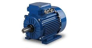
A motor is a device that converts electrical energy into mechanical energy. Specifically, rotational motion. Feed it electricity and a shaft spins. That spinning shaft can then drive wheels, fans, pumps, robotic arms, print heads, or anything else that needs to move.
How All Electric Motors Work
Every electric motor relies on the same fundamental principle: a magnetic field exerts a force on a current-carrying conductor. When you run current through a coil inside a magnetic field, the coil experiences a torque and rotates. The differences between motor types come down to how the current and magnetic field are arranged, and how the switching is handled to keep the rotation going.
How Motors Are Classified
| Classification | Categories |
|---|---|
| By power supply | DC motors (run on direct current), AC motors (run on alternating current) |
| By commutation method | Brushed (mechanical commutator), Brushless (electronic switching) |
| By control type | Open-loop (no position feedback), Closed-loop (encoder or resolver feedback) |
| By motion type | Continuous rotation, Incremental (stepper), Limited-angle (servo) |
Common Types in Electronics and Fabrication
- DC Motor — simple, continuous rotation, speed controlled by voltage or PWM.
- Stepper Motor — rotates in fixed discrete steps, open-loop position control without an encoder.
- Servo Motor — closed-loop, uses encoder feedback to confirm and correct position.
- Brushless DC (BLDC) — like a DC motor but with electronic commutation, higher efficiency and lifespan.
- AC Induction Motor — common in appliances and industrial machines, runs on mains AC power.
DC Motor
A DC (Direct Current) motor is an electromechanical device that converts electrical energy from a DC source into rotational mechanical energy. It is one of the oldest and most widely used motor types, found in everything from toys and fans to electric vehicles and industrial machinery.
How It Works
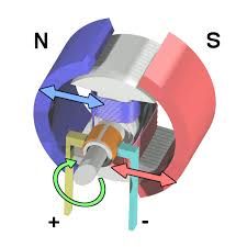
The working principle is based on the interaction between a magnetic field and a current-carrying conductor, described by the Lorentz force law: when a conductor carrying current is placed inside a magnetic field, it experiences a force. This force causes the rotor to spin.
A basic DC motor has two main parts: the stator (the stationary outer frame that produces a fixed magnetic field, either via permanent magnets or field windings) and the rotor (also called the armature — the rotating inner coil that carries current). When DC voltage is applied, current flows through the armature windings, generating a magnetic field that interacts with the stator field and produces torque.
To keep the motor spinning continuously, the current direction in the armature must reverse every half turn. In brushed motors, this is handled mechanically by a commutator (a segmented copper ring) and brushes (carbon contacts that slide along it). In brushless motors, an electronic controller handles this switching instead.
Types of DC Motors
| Type | How It Works | Typical Use |
|---|---|---|
| Brushed DC | Uses physical brushes and a commutator for current switching. Simple and cheap. | Toys, fans, basic robotics |
| Brushless DC (BLDC) | Electronic controller switches current — no brushes, longer lifespan, higher efficiency. | Drones, EVs, cooling fans, power tools |
| Coreless (Ironless) | Armature has no iron core — very low inertia, fast response, smooth torque. | Camera gimbals, medical devices, RC models |
| Series-Wound | Field winding connected in series with the armature — high starting torque but speed varies with load. | Cranes, electric traction, starters |
| Shunt-Wound | Field winding in parallel with the armature — more stable speed under varying load. | Lathes, conveyors, constant-speed drives |
| Compound | Combines series and shunt windings for a balance of high torque and stable speed. | Elevators, presses, printing machines |
Key Characteristics
- Speed control: Easily controlled by varying supply voltage or using PWM (Pulse Width Modulation).
- Direction control: Reverse the polarity of the supply voltage (or use an H-bridge circuit).
- Continuous rotation: Unlike steppers, DC motors spin continuously and are rated in RPM.
- No position feedback: Standard DC motors have no built-in position sensing — you need an encoder if you need to know where the shaft stopped.
Stepper Motor

A stepper motor, also referred to as a step motor or stepping motor, is a brushless DC electric motor that rotates in a series of small, discrete angular steps rather than spinning continuously like conventional DC motors.
Stepper motors find widespread use across diverse sectors, from consumer electronics such as printers and scanners to sophisticated industrial equipment including CNC machines, 3D printers, robotics, medical instruments, and precision optical systems.
Working Principle
The operation of a stepper motor is rooted in electromagnetic induction and the sequential energisation of stator windings.
Like all electric motors, a stepper motor consists of a stationary part (the stator) and a moving part (the rotor).
The stator contains multiple coils arranged in phases, while the rotor may be a permanent magnet, a toothed soft-iron structure, or a hybrid combination of both.
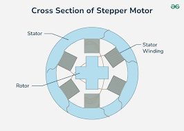
The fundamental operating sequence is as follows: when a current pulse is applied to a particular stator winding, it generates a magnetic field. The rotor aligns itself with this field due to magnetic attraction. When the next winding in the sequence is energised, the magnetic field shifts position, causing the rotor to advance by a fixed angular displacement—this displacement is known as the step angle. By continuously energising the windings in a specific order, the rotor rotates step by step. The step angle depends on the motor’s physical construction and determines how many steps are required for one complete revolution.
A typical stepper motor has a step angle of 1.8°, translating to 200 full steps per revolution. Mechanically, when the motor transitions from one step to the next, the rotor overshoots the target position and oscillates around it before settling—similar to a mass-spring system. The magnitude of this oscillation depends on the step size, load inertia, and damping characteristics.
Step Angle and Resolution
The step angle (θ) is the angular displacement of the rotor for each input pulse. It is determined by the motor’s construction and can be calculated using:
θ = 360° / (Nᵣ × Ø)
where Nᵣ is the total number of rotor teeth and Ø is the number of motor phases. Common step angles include 1.8° (200 steps/rev), 0.9° (400 steps/rev), and 7.5° (48 steps/rev).
Types of Stepper Motors
Stepper motors are classified into three primary types based on rotor construction: Permanent Magnet (PM), Variable Reluctance (VR), and Hybrid Synchronous. Each type offers distinct characteristics suited to different application requirements.
Stepper Motor Driver
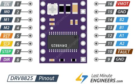
A stepper motor driver is an electronic amplifier that translates low-current signals from a microcontroller into the high-current pulses needed to rotate a stepper motor. It manages coil energization, controls the motor's direction, and often enables advanced microstepping for smoother, quieter, and highly precise positioning.
The DRV8825. Though small in size, this chip is packed with powerful features. This driver can handle up to 45V and deliver 2.5A of electrical current, which is enough power to run popular stepper motors like the NEMA 17 and NEMA 23.
One of the best features of the DRV8825 is its built-in "translator." Normally, you would need to send complex electrical signals to four different wires in a specific order; the translator simplifies this to two pins: STEP (one pulse equals one step) and DIR (direction).
Technical Specifications
| Property | Value |
|---|---|
| Motor output voltage | 8.2V – 45V |
| Logic voltage | Built-In 3.3V output |
| Continuous current per phase | 1A |
| Maximum current per phase | 2.5A |
| Microstep resolution | Full, 1/2, 1/4, 1/8, 1/16, and 1/32 |
Power Pins
VMOT and GND pins supply power to both the driver and the stepper motor. This voltage can range from 8.2V to 45V.
Microstepping Pins
The DRV8825 offers six resolution options configured via the M0, M1, and M2 pins.
| M0 | M1 | M2 | Microstep Resolution |
|---|---|---|---|
| Low | Low | Low | Full step |
| High | Low | Low | Half step |
| Low | High | Low | 1/4 step |
| High | High | Low | 1/8 step |
| Low | Low | High | 1/16 step |
| High | Low | High | 1/32 step |
| Low | High | High | 1/32 step |
| High | High | High | 1/32 step |
Note: These pins have internal pull-down resistors, so leaving them unconnected defaults the motor to Full-step mode.
Control Input Pins
- STEP: Each HIGH pulse moves the motor by one step. The pulse frequency determines the rotation speed.
- DIR: Controls rotation direction (HIGH for clockwise, LOW for counterclockwise).
Power State Control Pins
- EN (Enable): Active-low pin. Pulling it LOW enables the driver (default state).
- SLP (Sleep): Active-low pin. Pulling it LOW puts the driver into power-saving mode.
- RST (Reset): Active-low pin. Resets the driver and returns the motor to its starting position.
Note: Both SLP and RST must be HIGH to enable the driver. You can bridge them to a logic HIGH voltage or control them via microcontroller GPIO.
Fault Detection Pin
The FAULT output goes LOW whenever the driver detects an error condition like over-current or thermal shutdown. The driver remains disabled until RESET is toggled or VMOT power is cycled.
Output Pins
Connect your bipolar stepper motor coils here: A1/A2 for the first coil and B1/B2 for the second coil.
OLED
An Organic Light Emitting Diode (OLED) works by passing an electric current through organic material layers sandwiched between an anode and a cathode. When voltage is applied, the anode injects holes (positive charge) and the cathode injects electrons (negative charge) into these layers, which recombine in the emissive layer to create light through electroluminescence.
Advantages of OLEDs
- Self-Emissive: Unlike LCDs, OLED pixels create their own light, allowing for true blacks, higher contrast, and no need for a backlight.
- Thin & Flexible: Organic layers are thin, enabling flexible, foldable, and lightweight displays.
- High Response Times: They offer faster refresh rates, suitable for fast-paced content.
OLEDs are commonly used in smartphones, high-end TVs, and wearable devices.
I2C (4-Pin) Module
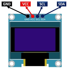
This is the most common version and requires only two data lines for communication. It is widely used due to its simplicity and low pin count.
- GND: Ground (0V).
- VCC: Power supply (typically 3.3V to 5V).
- SCL: Serial Clock line for I2C communication.
- SDA: Serial Data line for I2C communication.
SPI (7-Pin) Module
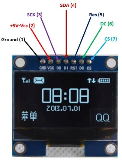
SPI is used for faster communication and offers more control pins. This interface is often preferred for applications requiring higher refresh rates or more complex graphics.
- GND: Ground (0V).
- VCC: Power supply (typically 3.3V to 5V).
- D0 (CLK): Serial Clock pin for SPI communication.
- D1 (MOSI): Serial Data pin for SPI communication.
- RES (RESET): Used to reset the display to its initial state.
- DC (Data/Command): Selects between sending data or commands to the controller.
- CS (Chip Select): Used to activate the display for communication.
BUZZER
The 9032 SMD Passive Buzzer is a compact electromagnetic sound component used for providing auditory feedback in miniature electronic devices. Unlike active buzzers, it requires an external oscillation circuit (PWM signal) to produce sound.
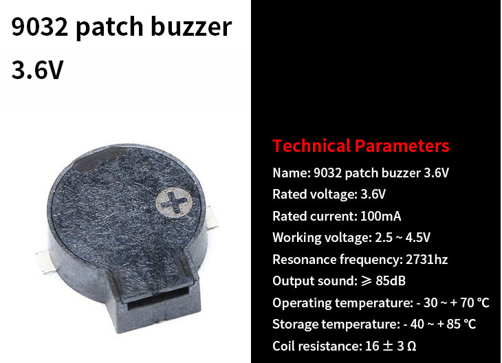
Usage Tips
- Drive Circuit: Use a MOSFET or Transistor to drive the buzzer from a microcontroller, as the 100mA current requirement may exceed the direct output capacity of standard GPIO pins.
- Tone Generation: By varying the frequency of the input PWM signal, you can generate different musical tones and vary the loudness of the alert.
Buzzer Driver — N-Channel MOSFET (Q1)
In this design, an N-channel MOSFET (Q1) is used as a low-side switch to drive the passive buzzer. A MOSFET is needed because the buzzer requires up to 100 mA, which exceeds the ~8–12 mA a typical GPIO pin can safely source.
| Pin | Label | Role |
|---|---|---|
| Gate | G | Control input — receives PWM signal from GPIO (D7) |
| Drain | D | Connected to the buzzer's negative terminal |
| Source | S | Connected to PWR_GND (ground) |
How It Works
- When the GPIO pin goes HIGH, the MOSFET turns ON — current flows from Drain to Source, completing the buzzer circuit.
- When GPIO goes LOW, the MOSFET turns OFF — the buzzer circuit is broken.
- Rapid switching at audio frequencies (e.g., 262 Hz for C4) is what produces the tone.
Individual Assignment
So for my assignment or this week, I wanted to use a stepper motor and an led. And I decided to use DRV8825 as the stepper motor driver.
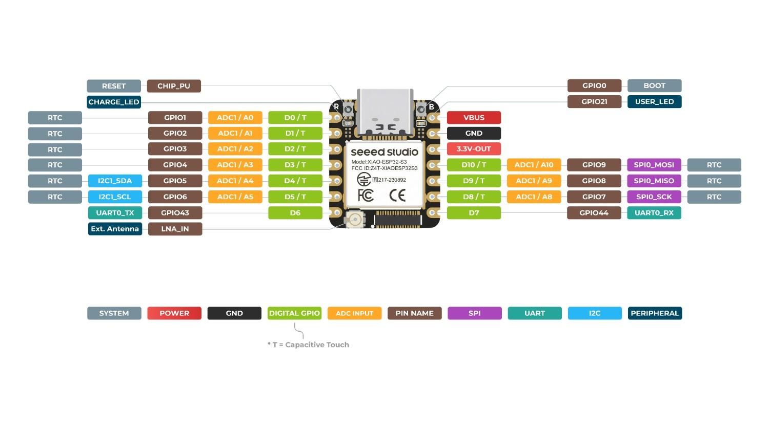
I chose Xiao ESP32C6 as the microcontroller.
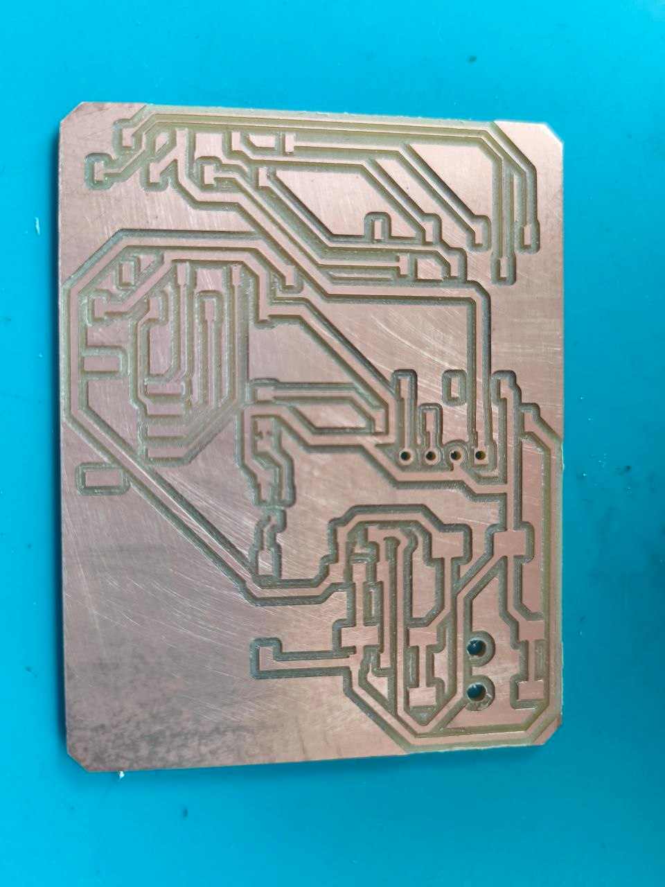
Designing a Custom Footprint for the DRV8825 Driver
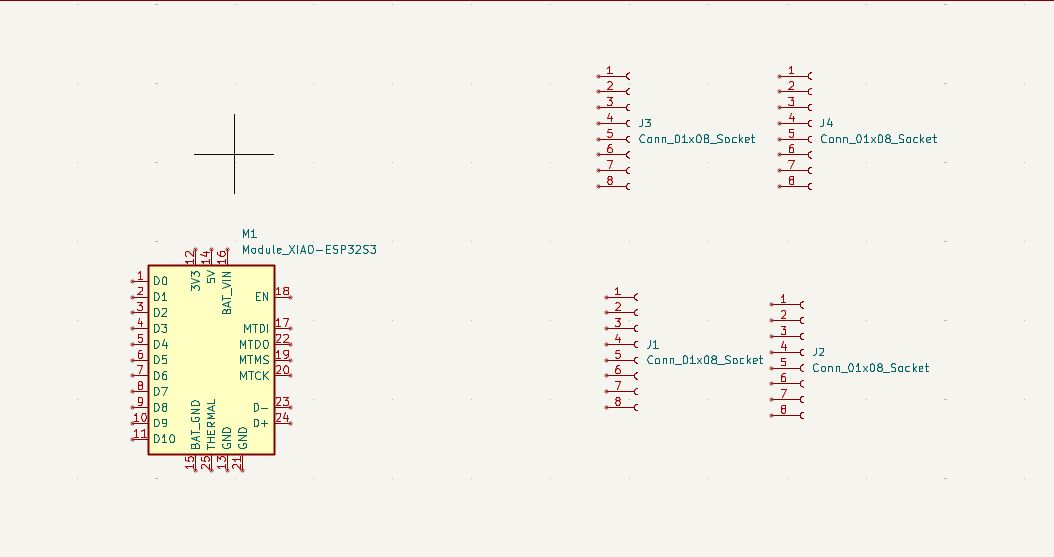
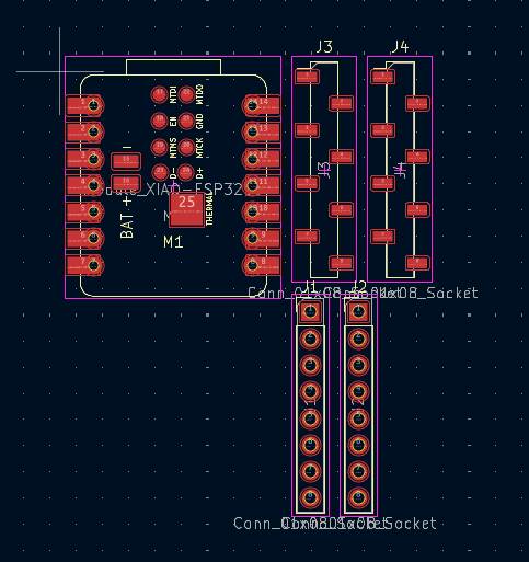
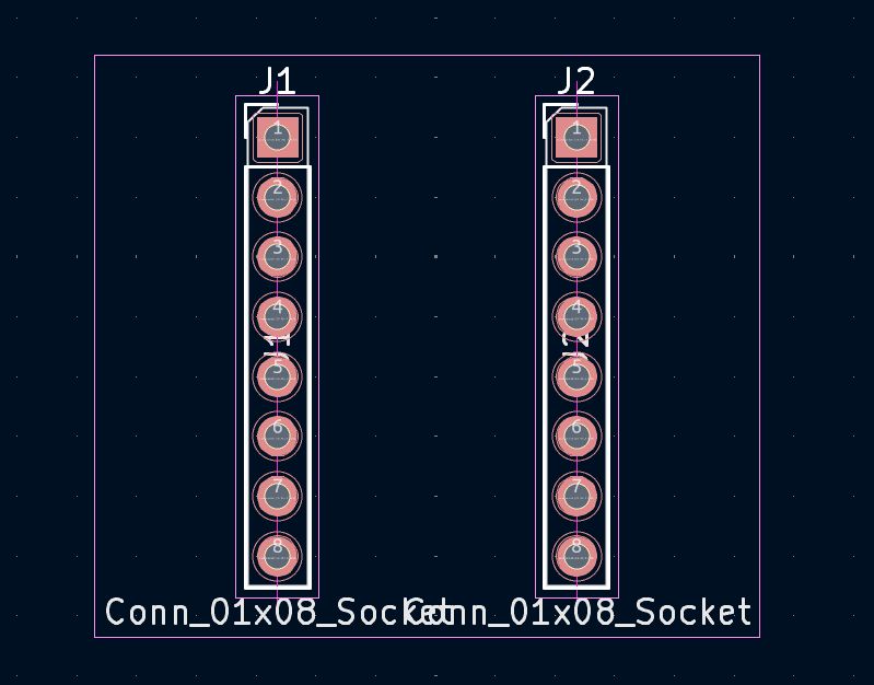
The DRV8825 module has two rows of 8 pins. To ensure a perfect fit on my custom PCB, I designed a specialized footprint in KiCad by aligning two 1x08 female header sockets.
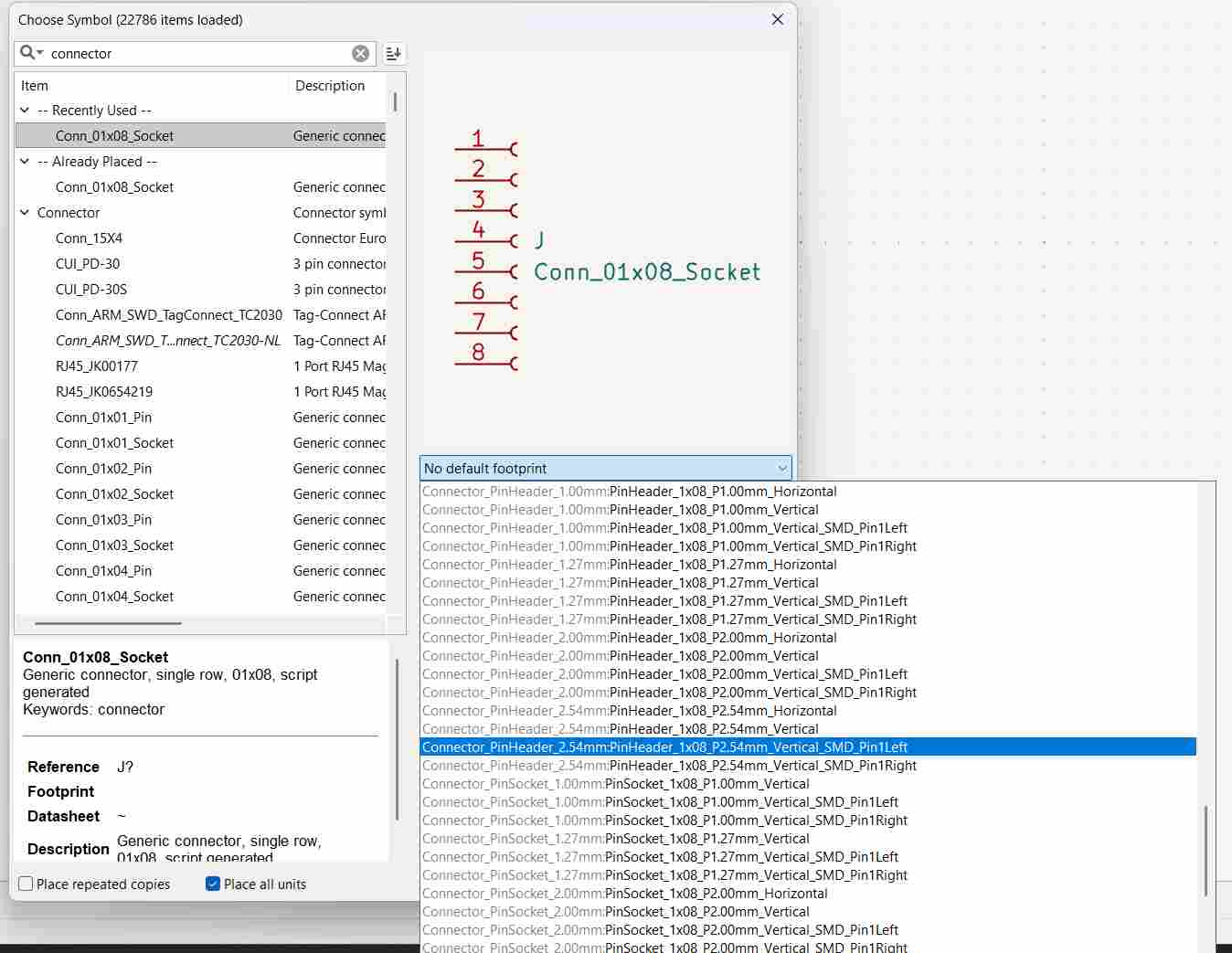
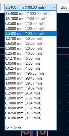
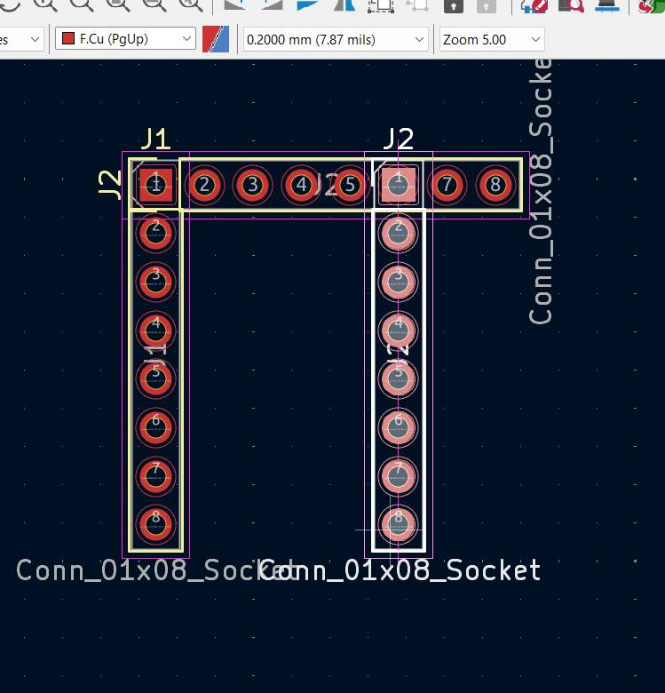
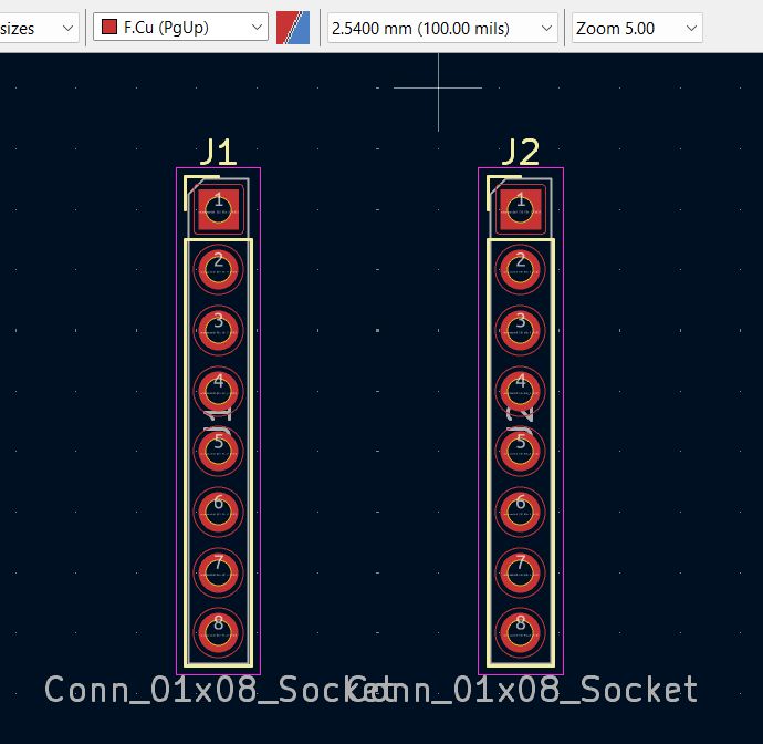
I updated the footprints in the PCB Editor and adjusted the grid to 2.54mm (0.1 inch) to match the standard breadboard pitch of the module.

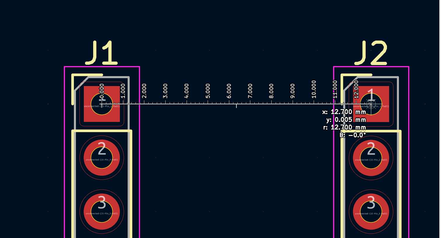
I matched the Y-coordinates of both rows to ensure they were perfectly parallel, then calculated the horizontal offset.
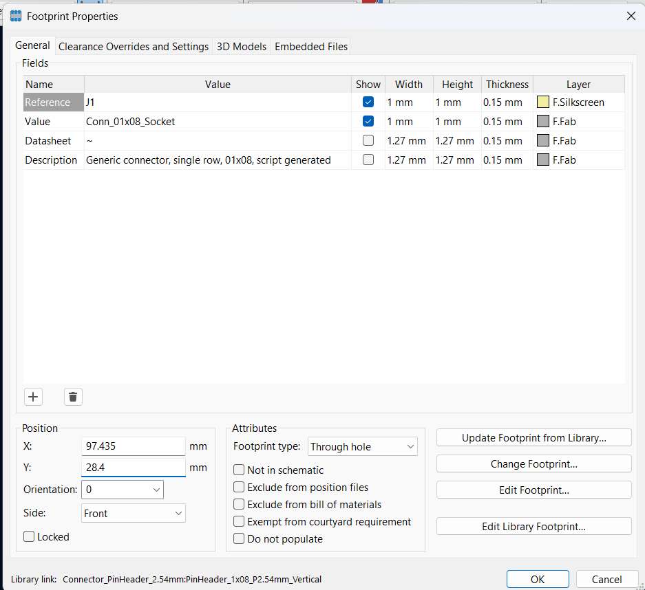
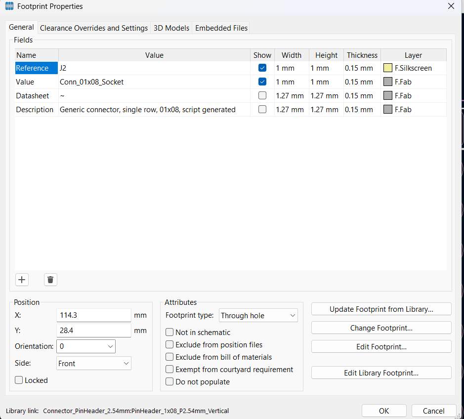
By measuring the physical DRV8825 board, I confirmed the span between the two rows is exactly 12.7mm (0.5 inches).
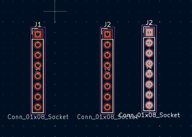
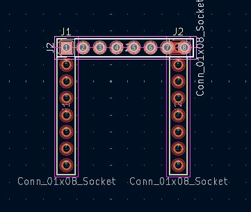
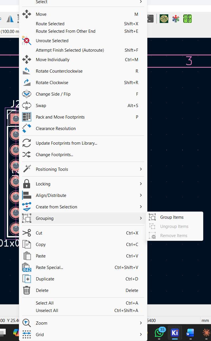
I grouped the components to preserve this relative spacing during the rest of the board layout process.
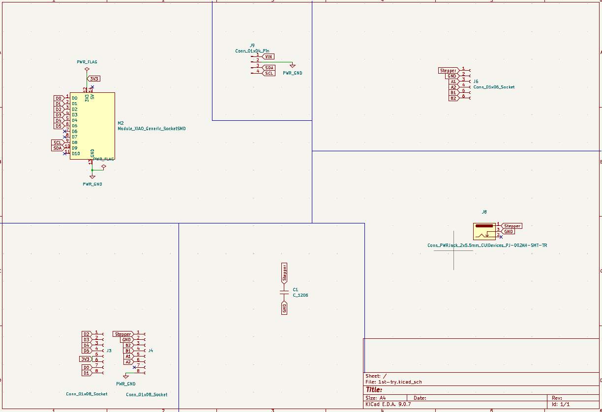
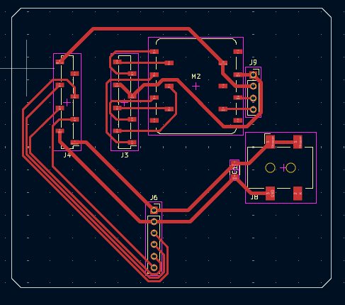
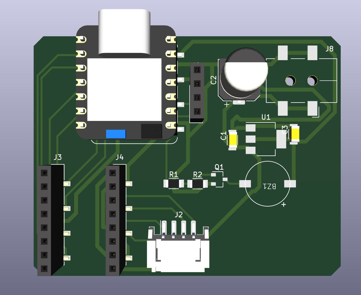
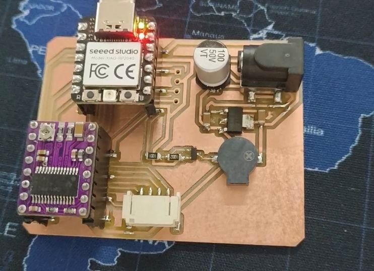
Final Schematic Overview
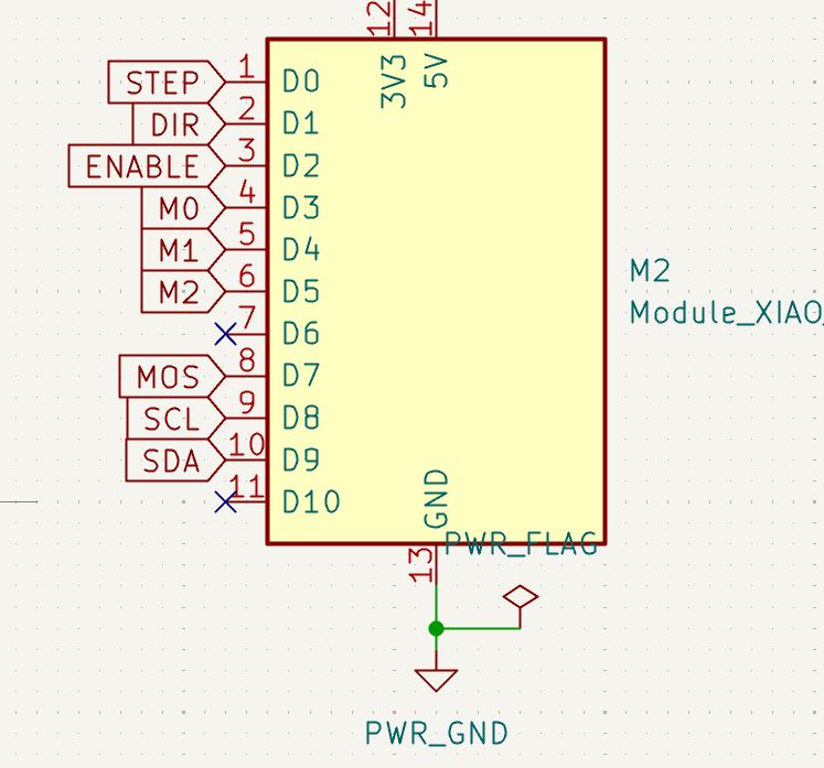
I integrated the custom footprint into the final design, which includes the XIAO controller, the DRV8825 driver, feedback LEDs, and a buzzer.
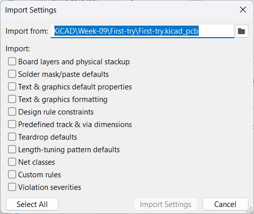
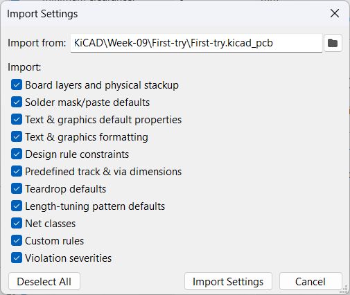
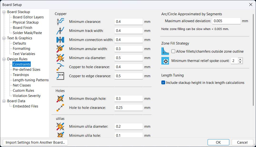
Instead of typing the constraints manually, I imported the settings from a previous board I made.
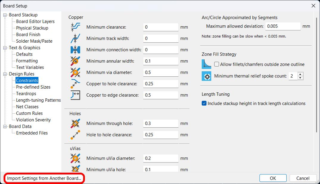
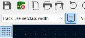
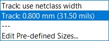
I used two different track width. I created them in the 'Pre-defined Sizes' tab.
.4 mm and .8 mm.
.8 mm was for power lines.
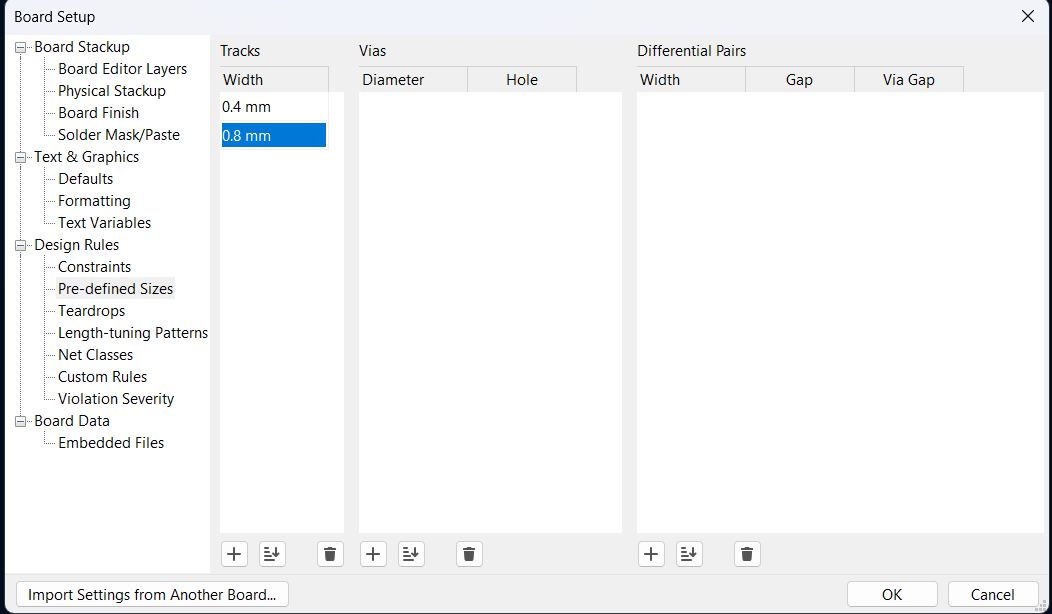
You can change the track widths in this tab.
Results
Buzzer
I wrote an Arduino sketch to play a melody on the passive buzzer using PWM. The prompt I gave was:
The code uses tone() to generate the PWM signal for each note frequency, with a 1.3× gap between notes for phrasing:
#define BUZZER D7

#define C4 262
#define D4 294
#define E4 330
#define F4 349
#define G4 392
#define A4 440

int melody[] = {
  C4, C4, G4, G4, A4, A4, G4,
  F4, F4, E4, E4, D4, D4, C4,
  G4, G4, F4, F4, E4, E4, D4,
  G4, G4, F4, F4, E4, E4, D4,
  C4, C4, G4, G4, A4, A4, G4,
  F4, F4, E4, E4, D4, D4, C4
};

int durations[] = {
  4, 4, 4, 4, 4, 4, 2,
  4, 4, 4, 4, 4, 4, 2,
  4, 4, 4, 4, 4, 4, 2,
  4, 4, 4, 4, 4, 4, 2,
  4, 4, 4, 4, 4, 4, 2,
  4, 4, 4, 4, 4, 4, 2
};

void setup() {
  pinMode(BUZZER, OUTPUT);
}

void loop() {
  int notes = sizeof(melody) / sizeof(melody[0]);
  for (int i = 0; i < notes; i++) {
    int duration = 1000 / durations[i];
    tone(BUZZER, melody[i], duration);
    delay(duration * 1.3);
    noTone(BUZZER);
  }
  delay(2000);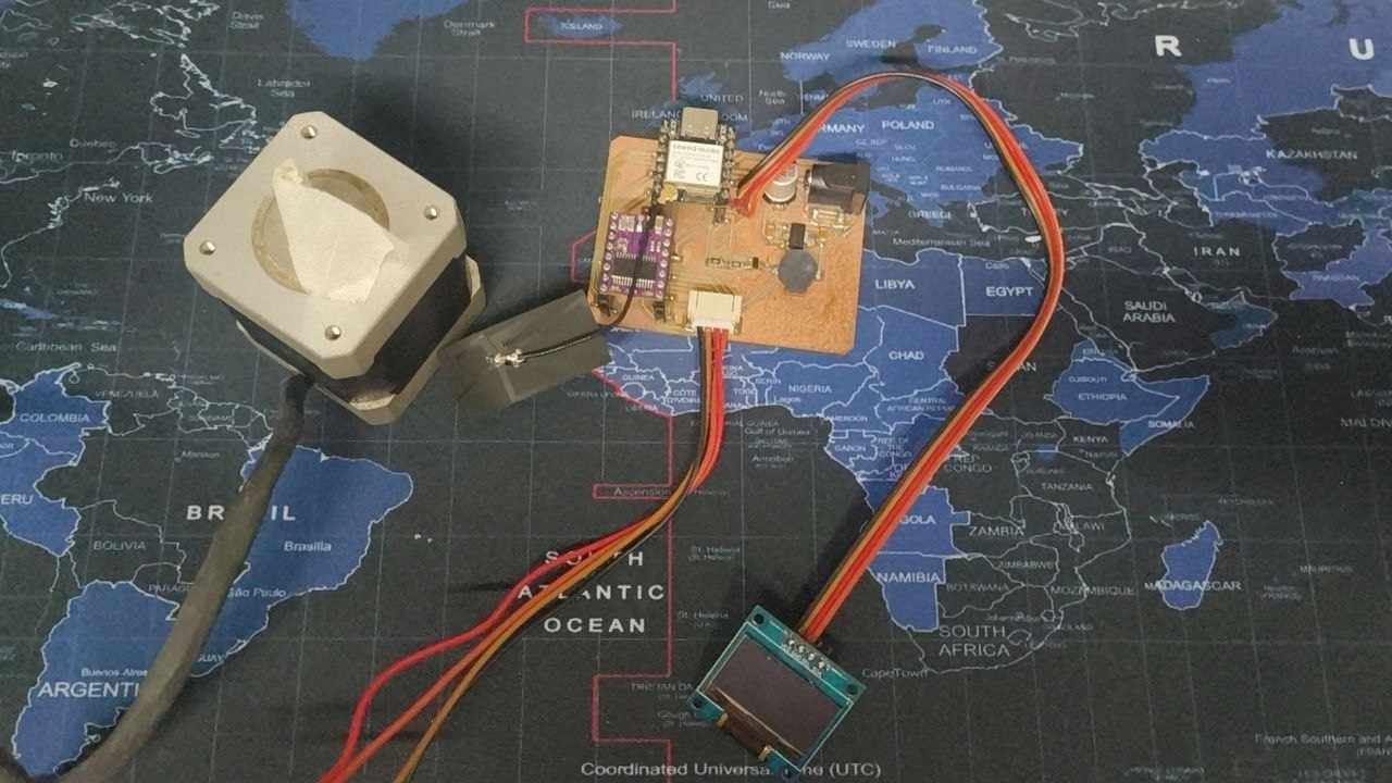
}Stepper Motor
I wrote a simple Arduino sketch to test the stepper motor running on the XIAO ESP32S3 with the DRV8825 driver. The prompt I gave was:
The code below initializes the driver in full-step mode, enables it, and spins the motor one revolution forward, pauses, then reverses:
#define STEP_PIN D0
#define DIR_PIN  D1
#define EN_PIN   D2
#define M0_PIN   D3
#define M1_PIN   D4
#define M2_PIN   D5

const int STEPS_PER_REV = 200;   // NEMA 17, 1.8°/step
const int MICROSTEPS    = 1;     // full step

void setup() {
  pinMode(STEP_PIN, OUTPUT);
  pinMode(DIR_PIN, OUTPUT);
  pinMode(EN_PIN, OUTPUT);
  pinMode(M0_PIN, OUTPUT);
  pinMode(M1_PIN, OUTPUT);
  pinMode(M2_PIN, OUTPUT);

  // Full step: M0=M1=M2=LOW
  digitalWrite(M0_PIN, LOW);
  digitalWrite(M1_PIN, LOW);
  digitalWrite(M2_PIN, LOW);

  digitalWrite(EN_PIN, LOW);   // active-low: enable driver
  digitalWrite(DIR_PIN, HIGH); // direction
}

void loop() {
  // One full revolution
  for (int i = 0; i < STEPS_PER_REV * MICROSTEPS; i++) {
    digitalWrite(STEP_PIN, HIGH);
    delayMicroseconds(800);
    digitalWrite(STEP_PIN, LOW);
    delayMicroseconds(800);
  }
  delay(1000);

  digitalWrite(DIR_PIN, LOW);  // reverse
}OLED
I found some problems in the pcb when I was testing it.
SDA and SCL were connected to the wrong pins during wiring. The schematic assigns SDA to D9 and SCL to D8. but the official documentatin shows that SDA is D4 and SCL is D5.
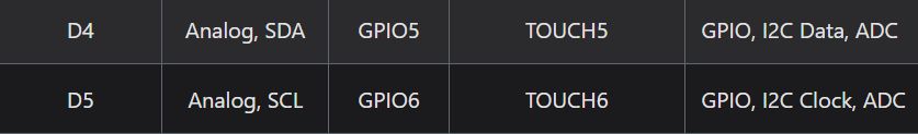
So I tried to fix it with software remapping. Instead of rewiring the board, I used Wire.begin(D9, D8) to tell the I2C library to use D9 as SDA and D8 as SCL — matching how they were physically connected on the PCB.
The Fix — Software Pin Remapping
The ESP32 family supports remapping I2C pins at runtime via the Wire.begin(SDA, SCL) call. By passing the actual physical pins used on the board, the firmware corrects for the wiring mistake without any hardware changes.
| Signal | Expected (Default) | Actual (PCB Wired To) | Fix |
|---|---|---|---|
| SDA | D4 | D9 | Pass D9 as first arg to Wire.begin() |
| SCL | D5 | D8 | Pass D8 as second arg to Wire.begin() |
The prompt I gave was:
OLED Code
#include <Wire.h>
#include <Adafruit_GFX.h>
#include <Adafruit_SSD1306.h>

Adafruit_SSD1306 display(128, 64, &Wire, -1);

void setup() {
  Wire.begin(D9, D8);  // Remap: SDA → D9, SCL → D8 (fix for wrong PCB wiring)
  display.begin(SSD1306_SWITCHCAPVCC, 0x3C);
  display.clearDisplay();
  display.setTextSize(2);
  display.setTextColor(SSD1306_WHITE);
  display.setCursor(0, 0);
  display.println("Hello");
  display.display();
}

void loop() {}
Code Breakdown
Wire.begin(D9, D8)— The key fix. Overrides the default I2C pins (D4, D5) and tells the library to use D9 for SDA and D8 for SCL, matching the physical PCB traces.Adafruit_SSD1306 display(128, 64, &Wire, -1)— Creates a display object for a 128×64 pixel OLED using I2C.-1means no reset pin is connected.display.begin(SSD1306_SWITCHCAPVCC, 0x3C)— Initialises the display with the internal charge pump and I2C address0x3C(the default for most SSD1306 modules).display.clearDisplay()— Clears the display buffer before drawing.display.setTextSize(2)— Sets font scale to 2× (each character is 12×16 pixels).display.setTextColor(SSD1306_WHITE)— Sets text colour to white (lit pixels).display.setCursor(0, 0)— Positions the text cursor at the top-left corner.display.println("Hello")— Writes "Hello" into the display buffer.display.display()— Pushes the buffer to the screen. Nothing appears until this is called.
Wire.begin(SDA_pin, SCL_pin). This made it possible to fix the wiring mistake in software without touching the PCB.
It worked