NETWORKING AND COMMUNICATIONS
Individual Assignment
- design, build, and connect wired or wireless node(s) with network or bus addresses and local input &/or output device(s)
This week's focus was on establishing communication between multiple microcontrollers. Networking is a fundamental skill in embedded systems that allows for distributed processing, for example, using one specialized board for sensing and another for acting.
Learn more about Communication Protocols
Goal
Board-to-board wireless communication between two microcontrollers using ESP-NOW.
I didn't have any idea what I wanted to do this week. First I thought using I2C communication, but I kinda wanted to do wireless as well. So I settled on a mix of both. A three-board network combining a wired bus and a wireless link.
Since I already used a board with ESP32-S3, I decided to communicate between boards using the wireless transmission capability of the ESP32. I started with two boards and then changed plans to a three-board network: the RP2040 has no WiFi, so it cannot do ESP-NOW.
So for this week, I designed and milled a simple board with an oled. It uses XIAO ESP32-C6 as the microcontroller. This board became the bridge between the wired and wireless halves of the network.
Communication System
The network uses two communication systems together: ESP-NOW for the wireless link between the two ESP32 boards, and I2C for the wired bus between the main board, the OLED, and the RP2040.
ESP-NOW (Wireless)
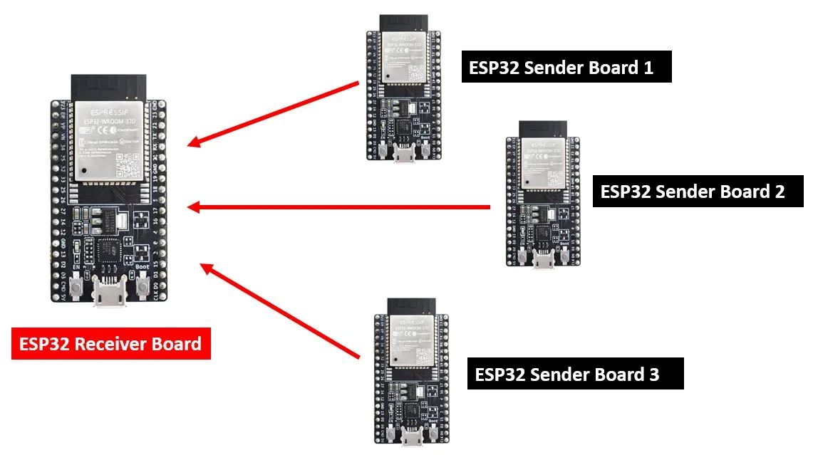
ESP-NOW is a connectionless wireless protocol made by Espressif. It lets two ESP32 boards exchange small data packets directly, without a router or a WiFi network, by pairing them with each other's MAC addresses. I used it for Board A ↔ Board C, since both boards have WiFi radios and it's much lighter than setting up a full WiFi/UDP connection for such a small payload.
References:
I2C (Wired Bus)
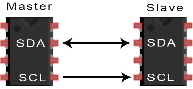
I2C is a two-wire bus (SDA + SCL) where one master talks to multiple slaves, each identified by a fixed 7-bit address. I used it for Board A ↔ OLED and Board A ↔ Board B, since both peripherals sit physically close to the main board and I2C needs only two data lines for any number of devices on the bus.
How I2C Works
I2C (Inter-Integrated Circuit), also called the Two-Wire Interface (TWI), is a serial bus protocol built for short-distance communication between chips. It only needs two bi-directional, open-drain lines:
- SDA (Serial Data) — carries the actual data
- SCL (Serial Clock) — carries the clock signal
Both lines sit high through pull-up resistors by default. Every device on the bus is active-low — it can only pull a line down, never drive it high itself, which is what lets multiple devices share the same two wires safely.
Data on SDA is synchronized to the clock on SCL, following one strict rule from the I2C spec: SDA must stay stable while SCL is high, and it's only allowed to change while SCL is low. That's what separates an actual data bit from a start/stop condition.
Data format: each transfer is built from a start condition, an address byte, and an acknowledge bit:
- Start Condition — 1 bit
- Slave Address — 8 bits
- Acknowledge (ACK) — 1 bit
Start and stop conditions are both just SDA changing while SCL is held high — the direction of the change is what tells them apart:
- Start Condition: SDA goes high → low while SCL is high.
- Stop Condition: SDA goes low → high while SCL is high.
Read/Write bit: a single R/W bit after the address sets the direction of the transfer — high means the master is writing to the slave, low means the master is reading from it.
Together, the shared two-wire bus, built-in addressing, and start/stop framing are what let several devices talk to one master over just SDA and SCL.
References:
- A Basic Guide to I2C
- Arduino — Wire library reference
- SparkFun — I2C protocol tutorial
- Electronics StackExchange — I2C timing diagram overlap
The Boards
Board A — XIAO ESP32-C6 (Main)
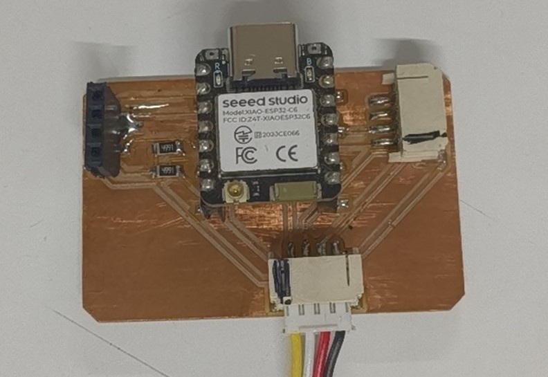
This is the custom PCB I designed and milled this week, built around a XIAO ESP32-C6 with an SSD1306 OLED on it. It's the board I actually type into — I open its serial monitor and send it single-letter commands, and it decides what to do with them.
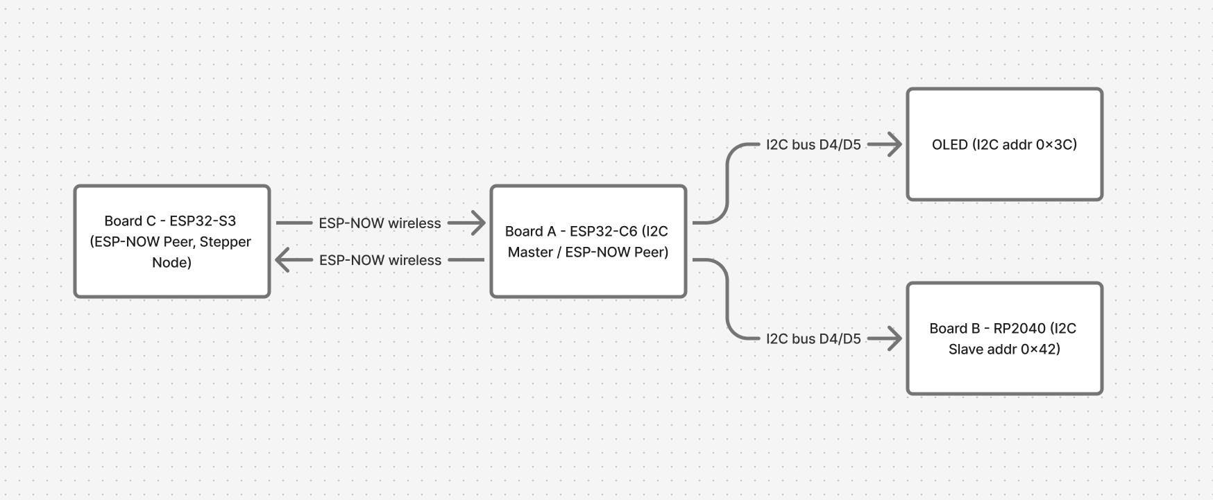
On the wired side, it acts as the I2C master on pins D4 (SDA) and D5 (SCL), driving both the OLED (address 0x3C) and the RP2040 (address 0x42) on that same bus. On the wireless side, it's paired as an ESP-NOW peer with the S3 board, using MAC address 7C:2C:67:64:BA:F8. Because it handles both the wired bus and the wireless link, this board is effectively the bridge between the two halves of the network.
Board B — XIAO RP2040 (LED node)
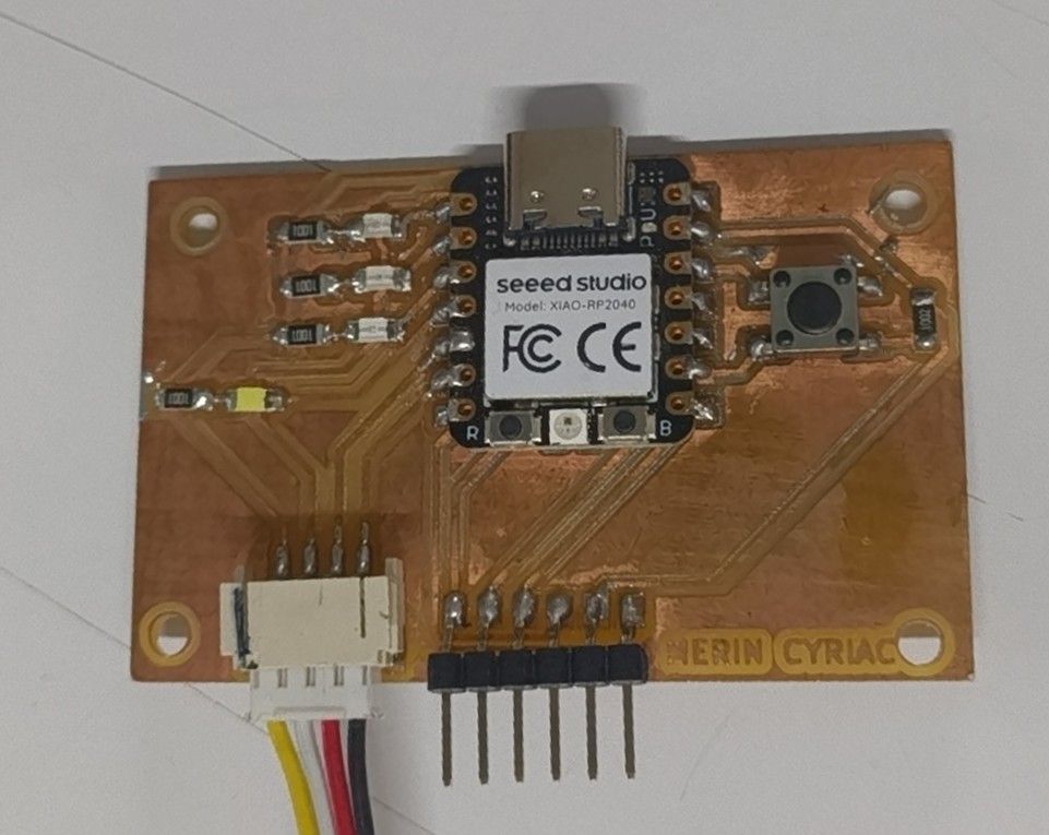
This board is left over from electronics production week. It's built around a XIAO RP2040, with a tactile push button for input, an SMD LED with a current-limiting resistor as a visual indicator, and pin headers broken out for wiring. Four extra LEDs sit on pins D0–D3, wired active HIGH.
On the network, it sits on the I2C bus as a slave at address 0x42, using the same D4 (SDA) / D5 (SCL) pins as Board A. It only understands one command byte: 0x01 tells it to start blinking its LEDs, and 0x00 tells it to stop. It has no WiFi, so it can't do ESP-NOW — it lives entirely on the wired side of the network. I made it the I2C slave rather than the master because the ESP32-C6 core doesn't have reliable I2C slave support, while the RP2040 handles slave mode without any issues.
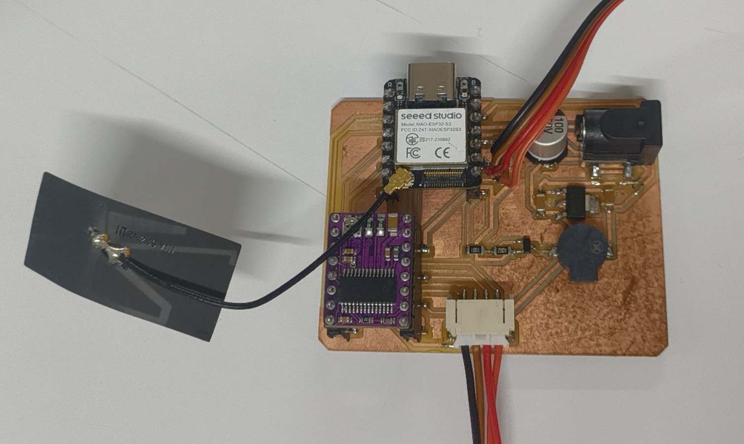
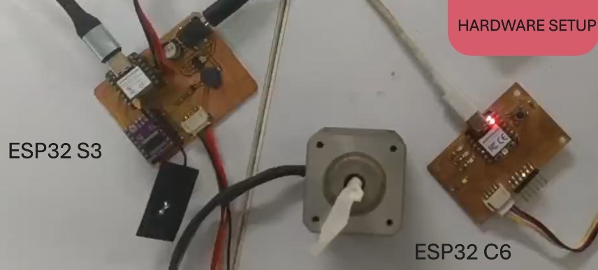
Board C — XIAO ESP32-S3 (Stepper node)
This board comes from output devices week, reused here. It's built around a XIAO ESP32-S3 driving a DRV8825 stepper driver and a NEMA 17 motor, plus an LED. The stepper pins are STEP=D0, DIR=D1, and EN=D2 (active-low), with M0=D3, M1=D4, M2=D5 all held LOW for full-step mode. Since the NEMA 17 moves 1.8° per step (200 steps per revolution), the sketch works out STEPS_PER_90 from a MICROSTEPS define, so the microstepping setting only needs to change in one place.
This board is paired with the C6 as an ESP-NOW peer, using MAC address 30:30:F9:34:60:2C. It receives a cumulative target angle from Board A, rotates the motor to reach it, and reports the actual angle and whether it's still moving back over the same link.
Note: the network only has three boards — A, B, and C. There is no fourth board. Board A already does double duty as both the I2C master and the ESP-NOW peer, so it acts as the bridge between the wired and wireless sides. A separate bridging board was never needed.
Network Topology
The C6 is the main board. I open its serial monitor and type single-letter commands. The C6 reads the command and relays it to the right place: over ESP-NOW (wireless) to the S3 stepper board, or over I2C (wired) to the RP2040 and its own OLED. The OLED and the RP2040 share the same I2C bus.
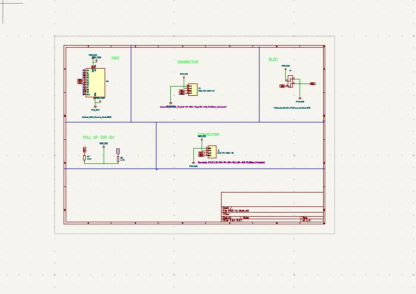
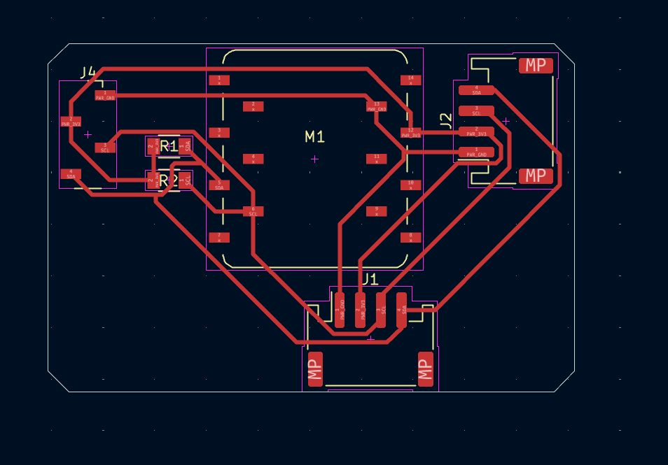
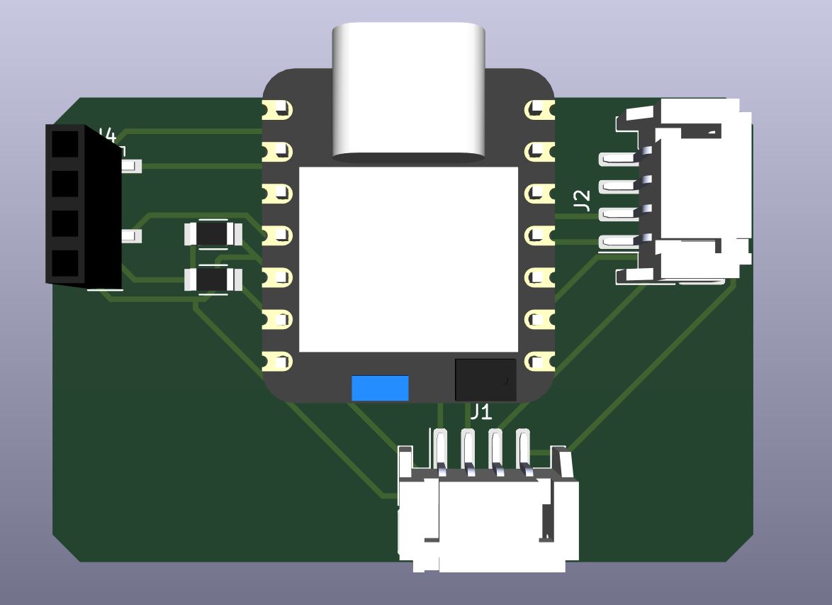
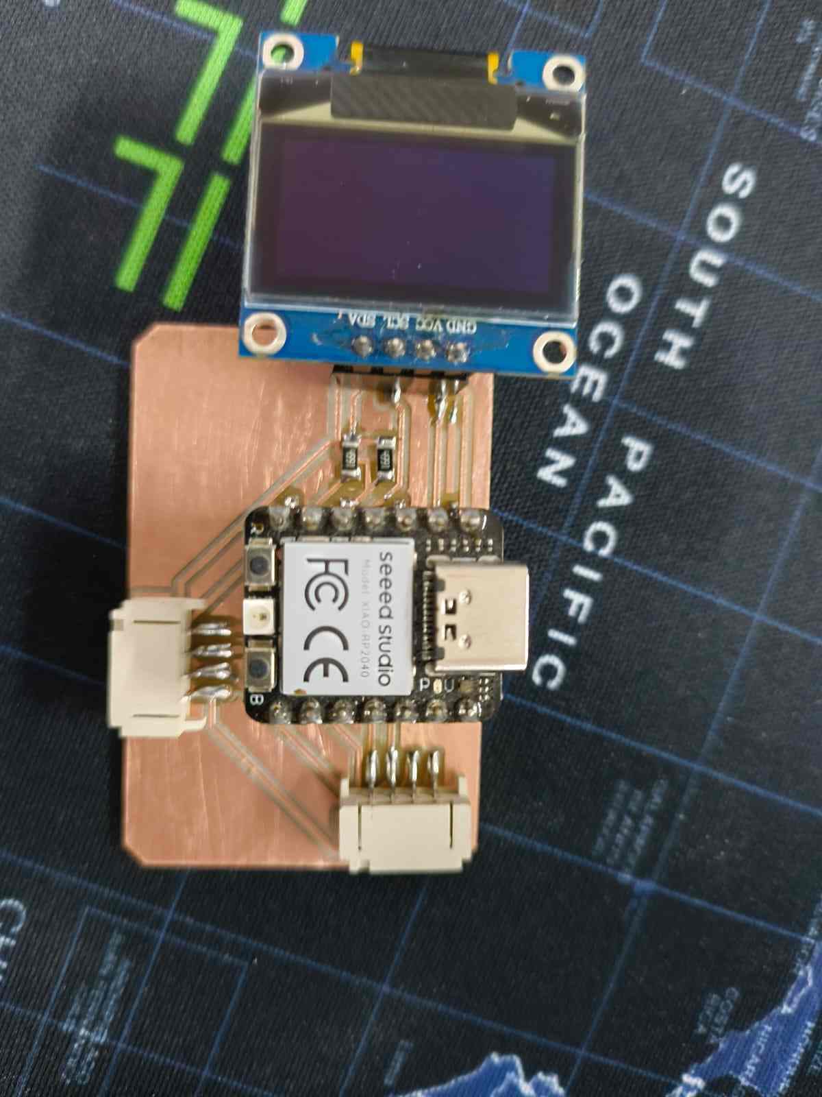
To complete the assignment, I started designing this week's board.
This is the board I designed and milled this week.
Addressing Each Node
The two halves of the network use two different addressing schemes: MAC addresses for the wireless ESP-NOW link, and 7-bit bus addresses for the wired I2C link.
ESP-NOW addressing (MAC based)
Each ESP-NOW peer is identified by its WiFi MAC address. Board A stores Board C's MAC as its peer, and registers it before it can send anything:
// on Board A (C6) — Board C's MAC is the peer address
uint8_t peerMac[] = {0x30, 0x30, 0xF9, 0x34, 0x60, 0x2C};

esp_now_peer_info_t peer = {};
memcpy(peer.peer_addr, peerMac, 6);
peer.channel = 1;
peer.encrypt = false;
esp_now_add_peer(&peer);
Board C does the same thing in reverse, storing Board A's MAC as its own peer, so both sides can send to each other directly.
I2C addressing (7-bit bus address)
On the wired bus, Board A is the master and both the OLED and Board B are slaves at fixed addresses: the OLED at 0x3C, Board B at 0x42. Board A picks which device to talk to just by choosing the address it writes to:
// on Board A (C6) — addressing Board B on the I2C bus
#define RP2040_ADDR 0x42
Wire.beginTransmission(RP2040_ADDR);
Wire.write(b);
Wire.endTransmission();
Board B listens for its own address by registering it when it starts up:
// on Board B (RP2040) — claiming address 0x42 as a slave
#define SLAVE_ADDR 0x42
Wire.begin(SLAVE_ADDR);
Wire.onReceive(onReceive);
Sending & Receiving Functions
Each link has its own pair of send and receive functions.
ESP-NOW — sending
Board A sends a target angle to Board C whenever 's' is typed:
// Board A: send a struct to Board C over ESP-NOW
out.targetAngle = targetAngle;
esp_now_send(peerMac, (uint8_t*)&out, sizeof(out));
Board C sends its status back the same way, using its own sendStatus() function:
// Board C: send angle + moving flag back to Board A
void sendStatus(uint8_t mv){
  status_t s; s.actualAngle = currentAngle; s.moving = mv;
  esp_now_send(peerMac, (uint8_t*)&s, sizeof(s));
}
ESP-NOW — receiving
Both boards register a callback that fires automatically whenever a packet arrives. The callback only copies the data and sets a flag — the real work happens in loop(), not inside the callback:
// Board C: receive the target angle from Board A
void onRecv(const esp_now_recv_info *info, const uint8_t *data, int len){
  cmd_t in;
  memcpy(&in, data, sizeof(in));
  targetAngle = in.targetAngle;
  newTarget = true;   // step in loop, not here
}
I2C — sending
Board A pushes a single command byte to Board B whenever 'o' is typed:
// Board A: send one byte to Board B (0x01 = blink, 0x00 = stop)
void i2cByte(uint8_t b){
  Wire.beginTransmission(RP2040_ADDR);
  Wire.write(b);
  Wire.endTransmission();
}
I2C — receiving
Board B's onReceive() callback fires whenever the master writes to it. It just reads the byte and sets a flag, and the LED blinking itself happens in loop():
// Board B: receive the command byte from Board A
void onReceive(int n){
  while(Wire.available()){
    uint8_t b = Wire.read();
    blinking = (b == 0x01);   // flag only, no heavy work
  }
}
Reading MAC Addresses
To establish a connection between the two ESP32 boards with ESP-NOW, I learned that you should first know about the MAC addresses of both boards.
I asked Claude for a code. When I first ran it, it gave the MAC address as 00:00:00:00:00:00 because the MAC was read before WiFi was initialized. Then I fixed it and ran it again.
The fix was to initialize WiFi in station mode and add a delay before reading the MAC address.
The code is given below.
#include <WiFi.h>
#include <esp_wifi.h>
void setup(){
  Serial.begin(115200);
  delay(1000);
  WiFi.mode(WIFI_STA);
  uint8_t mac[6];
  esp_wifi_get_mac(WIFI_IF_STA, mac);
  char buf[18];
  sprintf(buf, "%02X:%02X:%02X:%02X:%02X:%02X", mac[0],mac[1],mac[2],mac[3],mac[4],mac[5]);
  Serial.println(buf);
}
void loop(){}
My first idea was to make the RP2040 the main controller with a button, sending commands to the C6. This did not work. I learned that the ESP32-C6 Arduino core does not have reliable I2C slave support. When the RP2040 master scanned the bus, it found nothing, and writes returned an error. So I flipped the roles: the C6 became the I2C master and the RP2040 became the I2C slave. The RP2040 has solid peripheral (slave) mode support, and this combination worked.
Hardware
| Board | MCU | Peripherals | Role | Link | I2C / MAC |
|---|---|---|---|---|---|
| Master | XIAO ESP32-C6 | SSD1306 OLED | Master (timer + I2C master + ESP-NOW) | I2C + ESP-NOW | 7C:2C:67:64:BA:F8 |
| LED node | XIAO RP2040 | 4 LEDs (D0–D3) | I2C slave (output) | I2C (wired) | 0x42 (no WiFi) |
| Stepper node | XIAO ESP32-S3 | DRV8825 + NEMA 17 | Stepper node (ESP-NOW) | ESP-NOW | 30:30:F9:34:60:2C |
Then I used Claude to get the code to work both boards.
Full AI Prompt
The complete prompt used to generate both sketches, assembled from the project requirements:
i want to make a network of 3 boards for fab academy networking week. i control
everything by typing into the serial monitor of the main board. write me 3
arduino sketches.

the boards are:
- xiao esp32-c6 (has an oled). this is the main board, the one i type into.
- xiao rp2040 (has 4 leds). no wifi on this one.
- xiao esp32-s3 (has a drv8825 + nema 17 stepper).

what should happen:
i open the serial monitor of the c6 and type a letter.
- type 's' -> the c6 sends a message over esp-now (wireless) to the s3 and the
  stepper rotates 90 degrees. the s3 sends the angle back and the c6 shows it on
  the oled.
- type 'o' -> the c6 updates its own oled and sends a byte over i2c (wired) to
  the rp2040 to make its 4 leds blink.

wiring:
- the c6 is the i2c master (the c6 cant be a slave, its core doesnt support it).
- the oled (0x3c) and the rp2040 (0x42) are both on the c6's i2c bus, d4=sda
  d5=scl.
- rp2040 leds are on d0,d1,d2,d3, active high. it blinks them while told to
  (i2c 0x01 = blink, 0x00 = stop).

esp-now:
- c6 mac 7C:2C:67:64:BA:F8, s3 mac 30:30:F9:34:60:2C. no encryption.
- force both onto wifi channel 1 (esp-now silently failed before when they were
  on different channels).

stepper: nema 17 is 1.8 deg/step so 200 steps per rev. make microstepping a
#define so steps per 90 is calculated from it.
Board A Firmware (Main — XIAO ESP32-C6, serial + I2C master + OLED + ESP-NOW)
#include <WiFi.h>
#include <esp_wifi.h>
#include <esp_now.h>
#include <Wire.h>
#include <Adafruit_GFX.h>
#include <Adafruit_SSD1306.h>

#define RP2040_ADDR 0x42
Adafruit_SSD1306 display(128, 64, &Wire, -1);

// S3 stepper MAC
uint8_t peerMac[] = {0x30, 0x30, 0xF9, 0x34, 0x60, 0x2C};

typedef struct { uint32_t targetAngle; } cmd_t;
typedef struct { uint32_t actualAngle; uint8_t moving; } status_t;
cmd_t out;

volatile uint32_t actualAngle = 0;
volatile uint8_t  moving = 0;
volatile bool oledFlag = false;
uint32_t targetAngle = 0;
int oledCount = 0;

void onRecv(const esp_now_recv_info *info, const uint8_t *data, int len){
  status_t in;
  memcpy(&in, data, sizeof(in));
  actualAngle = in.actualAngle;
  moving = in.moving;
  oledFlag = true;                // redraw in loop, not here
}

void i2cByte(uint8_t b){
  Wire.beginTransmission(RP2040_ADDR);
  Wire.write(b);
  Wire.endTransmission();
}

void drawStepper(){
  display.clearDisplay();
  display.setTextSize(2);
  display.setCursor(0,0);
  display.println("STEPPER");
  display.setCursor(0,30);
  display.print((uint32_t)actualAngle);
  display.print(" deg");
  display.display();
}

void drawOled(){
  display.clearDisplay();
  display.setTextSize(2);
  display.setCursor(0,0);
  display.println("OLED CMD");
  display.setCursor(0,30);
  display.print("count: ");
  display.print(oledCount);
  display.display();
}

void setup(){
  Serial.begin(115200);
  delay(500);

  Wire.begin();                  // master: OLED + RP2040 on D4/D5
  display.begin(SSD1306_SWITCHCAPVCC, 0x3C);
  display.clearDisplay();
  display.setTextColor(SSD1306_WHITE);
  display.setTextSize(2);
  display.setCursor(0,0);
  display.println("ready");
  display.display();

  WiFi.mode(WIFI_STA);
  esp_wifi_set_channel(1, WIFI_SECOND_CHAN_NONE);   // force channel 1
  if(esp_now_init() != ESP_OK){ Serial.println("esp_now init fail"); return; }
  esp_now_register_recv_cb(onRecv);

  esp_now_peer_info_t peer = {};
  memcpy(peer.peer_addr, peerMac, 6);
  peer.channel = 1;
  peer.encrypt = false;
  esp_now_add_peer(&peer);

  Serial.println("C6 main ready");
  Serial.println("type 's' = stepper, 'o' = oled+leds");
}

void loop(){
  // handle a typed command
  if(Serial.available()){
    char c = Serial.read();
    if(c == 's'){
      targetAngle += 90;
      out.targetAngle = targetAngle;
      esp_now_send(peerMac, (uint8_t*)&out, sizeof(out));
      Serial.printf("TX stepper -> %u deg\n", targetAngle);
    }
    else if(c == 'o'){
      oledCount++;
      drawOled();
      i2cByte(0x01);             // RP2040: blink
      Serial.printf("OLED cmd #%d, leds blink\n", oledCount);
    }
  }

  // redraw OLED when stepper status comes back
  if(oledFlag){
    oledFlag = false;
    drawStepper();
    if(moving == 0) i2cByte(0x00);   // stepper done -> leds off
  }
}
Board B Firmware (LED node — XIAO RP2040, I2C slave + LEDs)
#include <Wire.h>

#define SLAVE_ADDR 0x42
const int LED_PINS[4] = {D0, D1, D2, D3};   // active HIGH

volatile bool blinking = false;

void onReceive(int n){
  while(Wire.available()){
    uint8_t b = Wire.read();
    blinking = (b == 0x01);     // flag only, no heavy work
  }
}

void setup(){
  Serial.begin(115200);
  for(int i = 0; i < 4; i++){
    pinMode(LED_PINS[i], OUTPUT);
    digitalWrite(LED_PINS[i], LOW);
  }
  Wire.begin(SLAVE_ADDR);       // RP2040 as I2C slave
  Wire.onReceive(onReceive);
  Serial.println("RP2040 slave ready");
}

void loop(){
  static bool on = false;
  static unsigned long last = 0;

  if(blinking){
    if(millis() - last > 150){
      last = millis();
      on = !on;
      for(int i = 0; i < 4; i++) digitalWrite(LED_PINS[i], on ? HIGH : LOW);
    }
  } else {
    if(on){
      on = false;
      for(int i = 0; i < 4; i++) digitalWrite(LED_PINS[i], LOW);
    }
  }
}
Board C Firmware (Stepper node — XIAO ESP32-S3)
#include <WiFi.h>
#include <esp_wifi.h>
#include <esp_now.h>

// ---- Stepper pins ----
#define STEP_PIN D0
#define DIR_PIN  D1
#define EN_PIN   D2
#define M0_PIN   D3
#define M1_PIN   D4
#define M2_PIN   D5

const int STEPS_PER_REV = 200;   // NEMA 17, 1.8 deg/step
const int MICROSTEPS    = 1;     // full step
const int STEPS_PER_90  = (STEPS_PER_REV * MICROSTEPS) / 4;

// C6 main MAC
uint8_t peerMac[] = {0x7C, 0x2C, 0x67, 0x64, 0xBA, 0xF8};

typedef struct { uint32_t targetAngle; } cmd_t;
typedef struct { uint32_t actualAngle; uint8_t moving; } status_t;

volatile uint32_t targetAngle = 0;
volatile bool newTarget = false;
uint32_t currentAngle = 0;

void sendStatus(uint8_t mv){
  status_t s; s.actualAngle = currentAngle; s.moving = mv;
  esp_now_send(peerMac, (uint8_t*)&s, sizeof(s));
}

void onSent(const wifi_tx_info_t *info, esp_now_send_status_t status){}

void onRecv(const esp_now_recv_info *info, const uint8_t *data, int len){
  cmd_t in;
  memcpy(&in, data, sizeof(in));
  targetAngle = in.targetAngle;
  newTarget = true;                 // step in loop, not here
}

void stepOnce(){
  digitalWrite(STEP_PIN, HIGH);
  delayMicroseconds(800);
  digitalWrite(STEP_PIN, LOW);
  delayMicroseconds(800);
}

void setup(){
  Serial.begin(115200);
  delay(500);

  pinMode(STEP_PIN, OUTPUT);
  pinMode(DIR_PIN, OUTPUT);
  pinMode(EN_PIN, OUTPUT);
  pinMode(M0_PIN, OUTPUT);
  pinMode(M1_PIN, OUTPUT);
  pinMode(M2_PIN, OUTPUT);
  digitalWrite(M0_PIN, LOW);
  digitalWrite(M1_PIN, LOW);
  digitalWrite(M2_PIN, LOW);
  digitalWrite(EN_PIN, LOW);      // active-low: enable
  digitalWrite(DIR_PIN, HIGH);

  WiFi.mode(WIFI_STA);
  esp_wifi_set_channel(1, WIFI_SECOND_CHAN_NONE);   // force channel 1
  if(esp_now_init() != ESP_OK){ Serial.println("esp_now init fail"); return; }
  esp_now_register_send_cb(onSent);
  esp_now_register_recv_cb(onRecv);

  esp_now_peer_info_t peer = {};
  memcpy(peer.peer_addr, peerMac, 6);
  peer.channel = 1;
  peer.encrypt = false;
  esp_now_add_peer(&peer);
  Serial.println("S3 stepper ready");
}

void loop(){
  if(newTarget){
    newTarget = false;
    while(currentAngle < targetAngle){
      sendStatus(1);                       // moving
      for(int i = 0; i < STEPS_PER_90; i++) stepOnce();
      currentAngle += 90;
      Serial.printf("at angle: %u\n", currentAngle);
    }
    sendStatus(0);                         // done
  }
}
The C6 runs a software timer. Every 5 seconds it adds 90 to the cumulative target and does three things: sends the new target to the S3 over ESP-NOW, tells the RP2040 to start blinking over I2C, and updates the OLED. The S3 rotates the stepper by 90 degrees and reports the actual angle back over ESP-NOW. When the C6 sees that the motor has finished moving, it tells the RP2040 to stop blinking. So a single timer tick exercises both the wired and the wireless link at once.
Results
So I went and flashed all three boards.
Why Board B isn't in the demo: the video only shows Board A (C6) and Board C (S3) talking over ESP-NOW — the stepper moving and the angle coming back. Board B, the RP2040 LED node, was not working at demo time, so its I2C blinking half of the network isn't shown. The I2C code itself (Board A sending, Board B receiving) is written and documented above, it just isn't demonstrated on camera because of that hardware issue on Board B.
Group Assignment
- send a message between two projects
View full group assignment page →
Reflection: Doing the group assignment right after my own board work made it much easier to see what "networking" actually means in practice, not just on one board but between completely different projects. We connected boards from different builds and sent a message across them, and it was interesting to see how everyone had approached addressing and protocol choice differently.
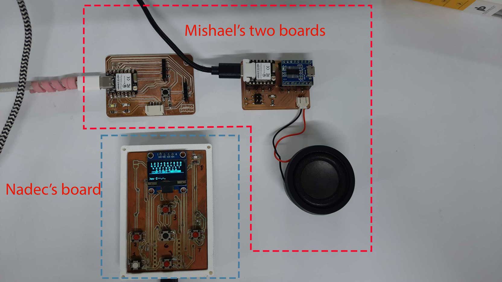
Nadec Biju and Mishael connected their project boards using a hybrid Wi-Fi TCP and ESP-NOW setup.
Nadec's custom PCB (ESP32, six push buttons, OLED) runs as a Wi-Fi access point with a TCP server, displaying a QWERTY keyboard on its OLED for text input. Mishael's system uses two XIAO ESP32-C6 boards — a main board that connects to Nadec's Wi-Fi as a TCP client to receive the typed text, and a secondary board linked via ESP-NOW that drives an MP3 player and speaker.
The result: text typed on Nadec's OLED travels over Wi-Fi/TCP to Mishael's main board, then over ESP-NOW to the secondary board, which plays it as audio.