MECHANICAL DESIGN & MACHINE DESIGN
This week was a group project week. All 10 students at Fablab Kochi came together, brainstormed machine ideas, then split into two groups of five. My group built the Pixel Art Machine, a CoreXY bead-placement CNC that physically recreates pixel art by dropping black and white beads into a perforated acrylic sheet, one bead per pixel.
My roles in the team were Electronics and Documentation.
Ideation
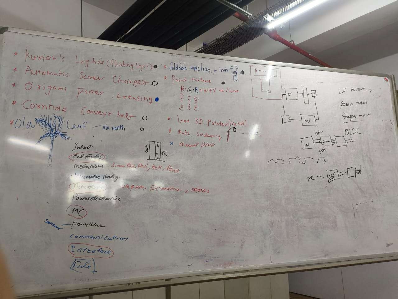
We started with a full group brainstorm. Everyone put forward machine ideas on the whiteboard, anything from fun to functional. The ideas ranged widely:
- Kurian's Lights — floating light display
- Automatic Scene Changer
- Origami Paper Creasing machine
- Cornhole Conveyor Belt
- Ola Leaf — ola pantu machine
- Foldable machine with Iron
- Paint Mixture machine (R + G + B → colours)
- Metal 3D Printer
- Auto Soldering machine
- Manual Drip
Alongside the ideas, we mapped out the generic structure of any machine — end effector, mechanism, electronics, firmware, sensors, communication, interface — to make sure whatever we built could be broken down into clear roles.
After discussing the ideas, the 10 of us divided into two groups of five. My group chose the Pixel Art Machine.
Our Group
The project was split across five roles:
- Nadec Biju — Machine Gantry (CoreXY design in SolidWorks)
- Kevin J Jijo — End Effector (bead dropper mechanism)
- Merin — Electronics & Documentation
- Architha B K — Firmware & Presentation
- Kurian — Interface & Fabrication
Concept Sketching
After settling on the Pixel Art Machine, we sketched out the machine on the whiteboard to figure out how all the parts would work together. The main things we needed to resolve at this stage were:
- How the drop mechanism would work, we sketched several funnel shapes and gate ideas for the end effector
- How the bead would travel from the container down to the hole in the acrylic sheet
- What the perforated acrylic grid would look like and how the machine would index across it
- Which team member was responsible for each subsystem
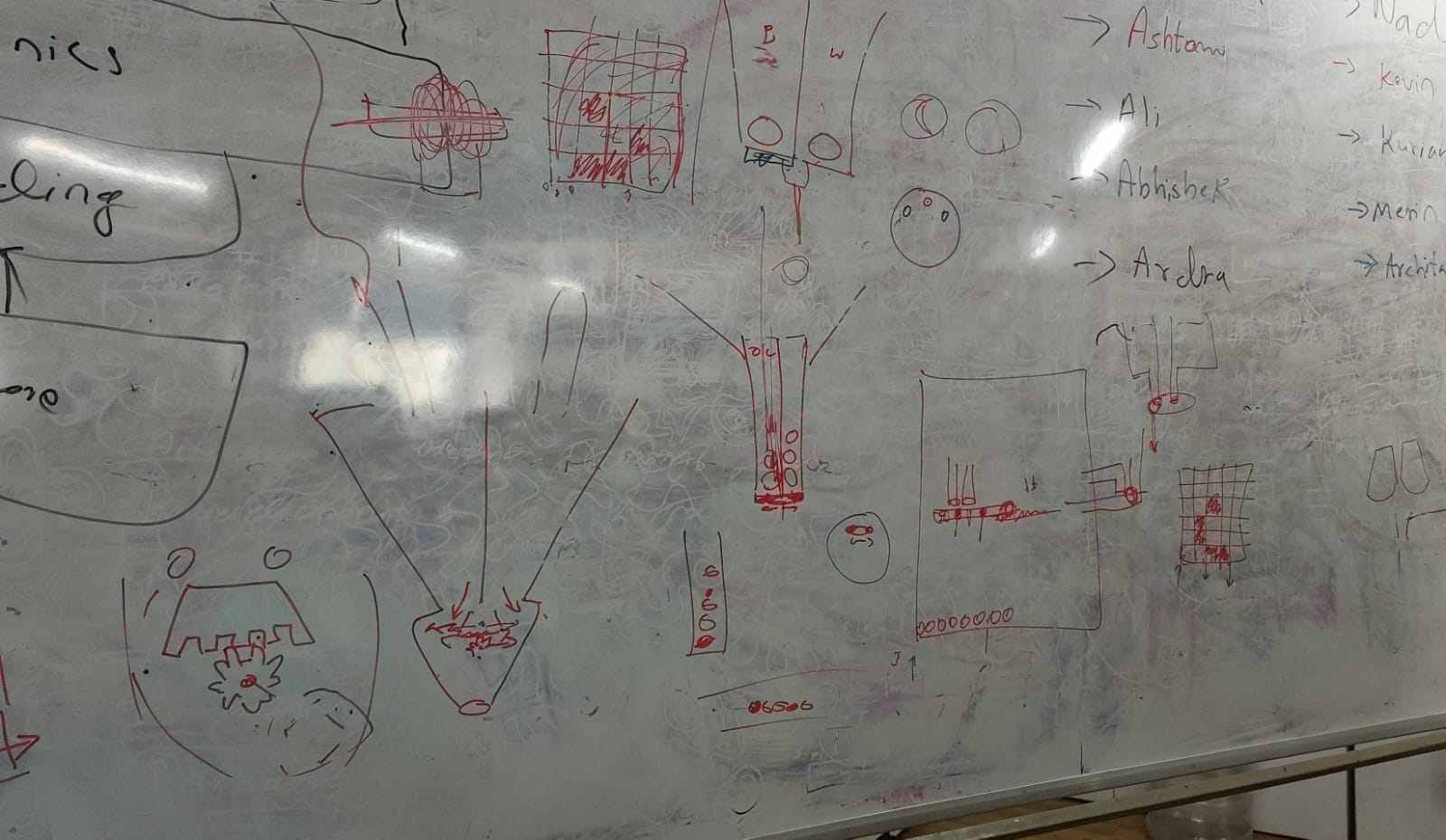
The sketches helped us align on the physical layout before anyone started designing in CAD. The funnel-shaped containers on the left explore different ways to hold and feed beads into the drop channel. The grid on the right represents the acrylic substrate and how the machine would traverse it row by row.
Individual Assignment
Within the group, my two roles were Electronics and Documentation. Here is what I was personally responsible for:
- Writing and publishing the group documentation site
- Project management — creating and maintaining the Gantt chart
- Drawing the electronics block diagram
- Designing the PCB in KiCad
- Testing the limit switches
Documentation
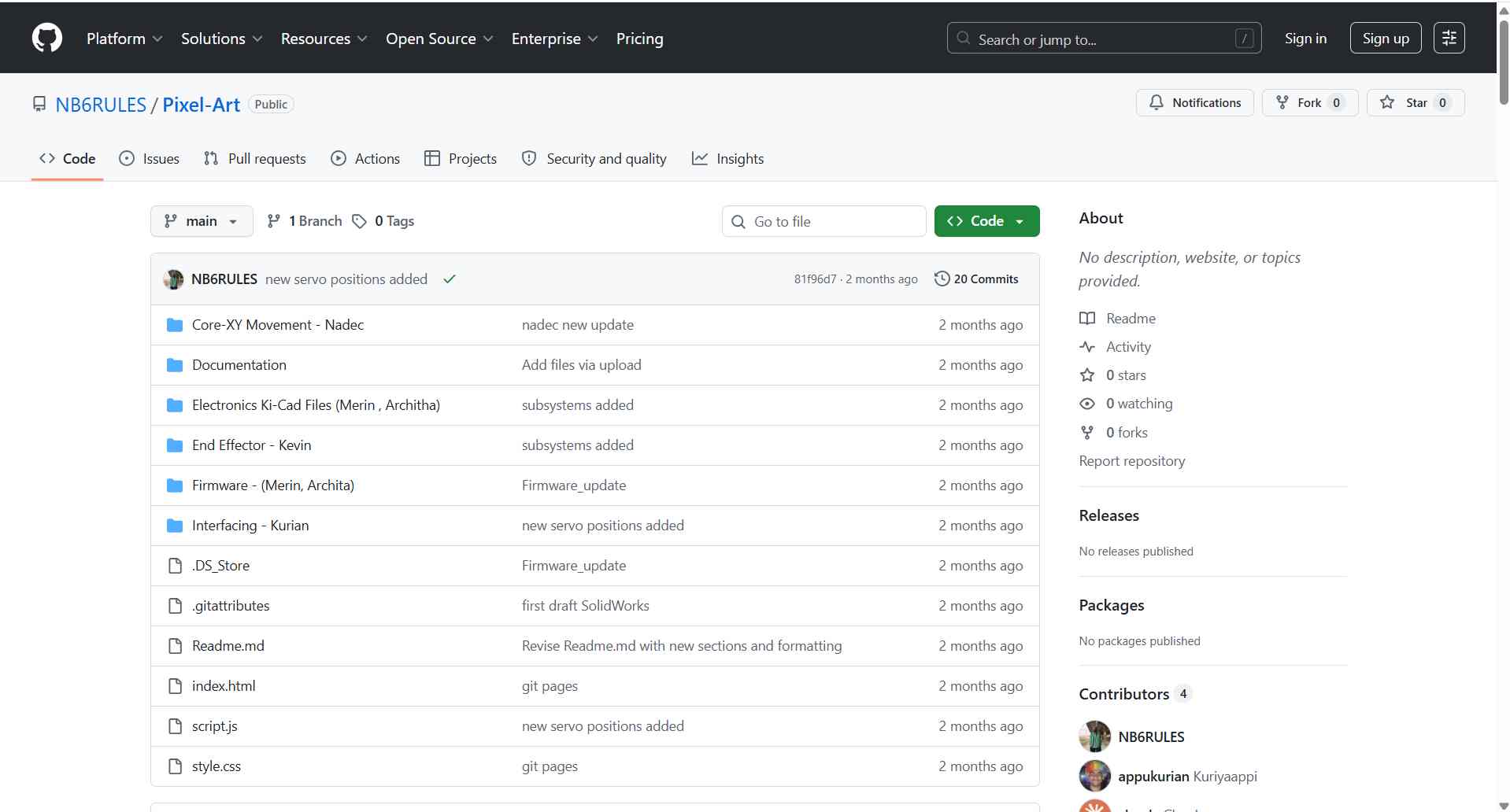
I was responsible for documenting the entire group project. That meant writing up the gantry design, end effector, firmware, and the web interface as well as the electronics, pulling together notes and photos from the rest of the team. The full site is on GitHub.
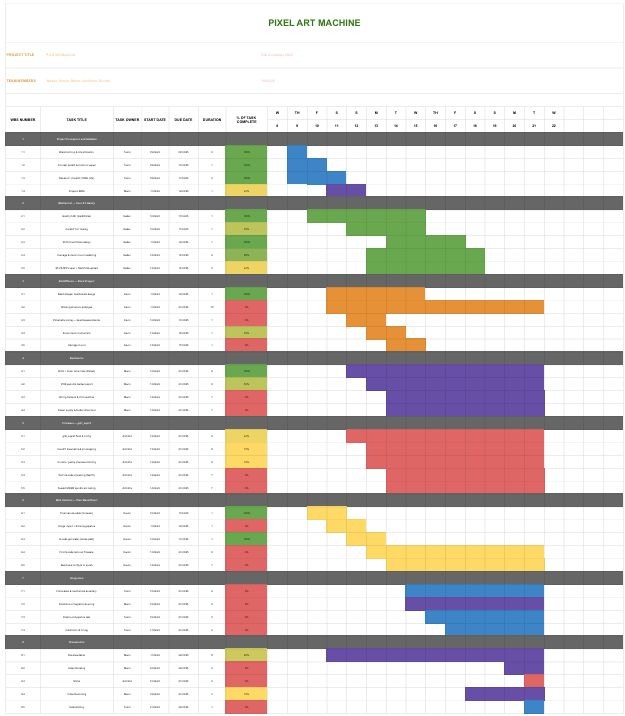
View Group Documentation Site →Project Management
To keep track of who was doing what and when, I put together a Gantt chart mapping out the full project timeline across all five roles. The main challenge was that some things were blocked by others, the firmware couldn't be tested until the electronics were ready, and the end effector couldn't be assembled until the gantry was built. The chart helped make those dependencies visible early.
All project files — CAD, fabrication files, code, and documentation — were committed to the project repository and published through GitHub Pages. The repository serves as the single source for reproducing the machine, and the Pages site presents the documentation in a browsable form.
PCB Design
Before starting the schematic, I drew a block diagram to map out all the electronic components and how they connect to the MCU.
The Pixel-Art electronics stack drives a CoreXY motion platform that positions a bead-dropping end effector over a laser-cut acrylic grid. The controller receives G-code over a USB serial connection and executes it using a port of Grbl running on an ESP32.
The electronics are responsible for four things: two-axis CoreXY stepper motion, servo actuation of the rotating-disc escapement that releases one bead at a time, USB-serial G-code streaming from the host, and regulated power distribution from a single DC input.
| Specification | Details |
|---|---|
| Motion system | CoreXY, 2 stepper motors (X/Y), frame-fixed |
| Stepper drivers | 2 × DRV8825 (socketed modules) |
| End effector | Servo-driven rotating-disc bead escapement (no Z axis) |
| Build area | ~400 × 400 mm |
Architecture
The signal flow from host to mechanism:
Python host  →  Serial Communication  →  ESP32 (Grbl_ESP32)  →  DRV8825 ×2  →  X/Y steppers  →  CoreXY belts
                                   →  servo PWM  →  bead escapement disc
Both CoreXY motors are frame-fixed and always run together; the toolhead's direction is set by the combination of the two motor directions, not by one motor per axis. The firmware handles this transform internally — the host only sends standard X/Y coordinates.
Power Distribution
A single 12 V DC supply enters through the barrel jack. It feeds the DRV8825 motor supply rail directly and is stepped down to 5 V for the ESP32 and servo by the AMS1117-5V linear regulator.
| Rail | Source | Loads |
|---|---|---|
| 12 V (VMOT) | Barrel jack | DRV8825 motor supply (both drivers) |
| 5 V | AMS1117-5V | ESP32 (via VIN/5V pin), servo Vcc |
| 3.3 V | ESP32 on-board LDO | Logic, driver logic supply, pull-ups |
Pin Mapping
Only the X and Y axes are used for motion. The Z/spindle channel is repurposed to actuate the bead dispenser — no firmware source changes are required.
| Function | ESP32 GPIO | Notes |
|---|---|---|
| X Step | D5 | CoreXY motor A |
| X Direction | D6 | |
| Y Step | D2 | CoreXY motor B |
| Y Direction | D3 | |
| Steppers Enable | D4 | Common enable for both DRV8825 |
| X Limit | D8 | Homing endstop (X) |
| Y Limit | D9 | Homing endstop (Y) |
| Spindle PWM | GPIO 2 | Repurposed → servo signal (bead dispenser) |
| Spindle Enable | D10 | Optional dispenser enable |
The diagram has three output branches from the MCU:
- Motor Driver 1 → Stepper Motor 1 — one of the two CoreXY drive motors. The limit switch feeds back to the MCU for homing.
- Stepper Motor 2 (via Motor Driver 2) → Stepper Motor 2 — the second CoreXY drive motor, also with a limit switch for homing on the other axis.
- Servo Motor — directly driven by the MCU, used to actuate the bead drop gate in the end effector.
The dotted lines represent sensor feedback (limit switches back to the MCU). The solid lines are control outputs.
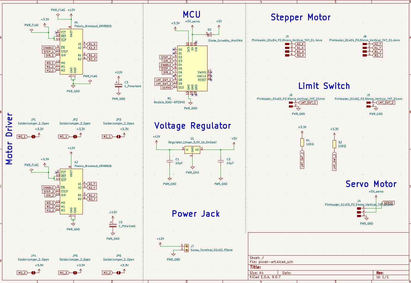
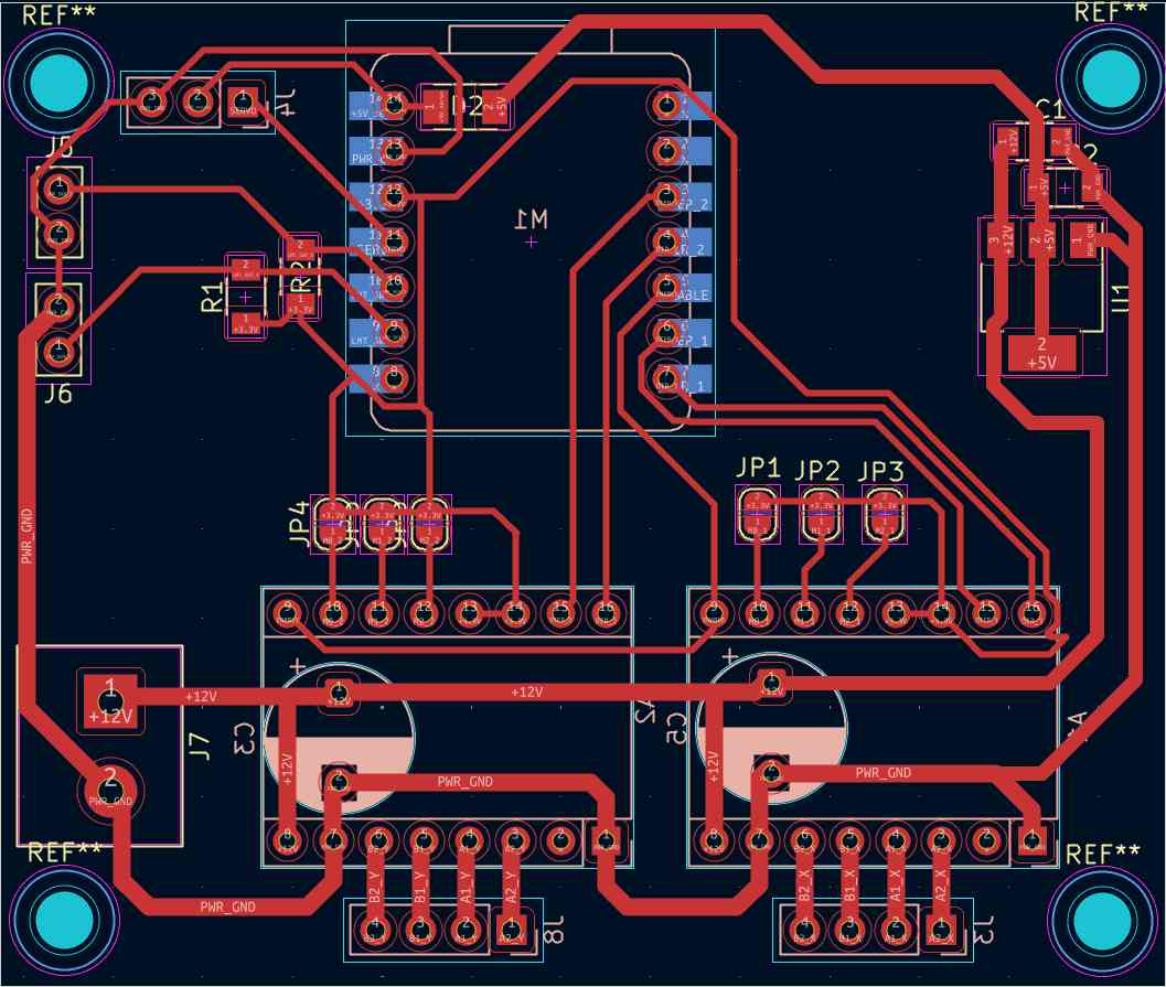
I designed the control board in KiCad. The board brings together the RP2040, two DRV8825/TMC2209 stepper drivers, limit switch inputs, and feeder control outputs onto a single board.
The main things I had to work through during layout:
- Keeping motor driver traces short and away from the RP2040 signal lines to reduce noise
- Adding a logic-level voltage divider
- Breaking out all the limit switch and feeder pins with enough clearance for connectors
Bill of Materials
| Component | Details |
|---|---|
| Microcontroller | RP2040 development board |
| Stepper Drivers | DRV8825 / TMC2209 (×2 for XY axes) |
| Power Supply | 12V / 24V DC |
| Limit Switches | ×2 (X, Y) |
| Feeder Outputs | M3 (black bead), M4 (white bead) via spindle pins |
| Communication | USB serial & serial communication (RP2040 native) |
The schematic and PCB layout were done in KiCad. The board routes stepper driver signals from the RP2040 GPIO pins, provides 3.3V logic level compatibility, and breaks out the limit switch inputs and feeder control outputs.
How the Machine Works
The software pipeline runs from image to physical bead placement:
- Image Input — A monochrome image is loaded into Kurian's browser-based Pixel Bead Placer tool
- Thresholding — Each pixel is converted to black or white based on its brightness
- G-code Generation — The tool maps pixel coordinates to hole positions and generates a G-code file
- Wireless Streaming — G-code is sent over serial communication to the RP2040 via the NeoPI_Wireless approach
- Bead Placement — The CoreXY gantry moves to each hole, activates the correct feeder (M3 for black, M4 for white), and drops a bead
Machine Specifications
| Parameter | Value |
|---|---|
| Build Area | 400 × 400 mm |
| Bead Diameter | 6.5 mm |
| Color Mode | Monochrome — black & white beads |
| Motion System | CoreXY (2× NEMA17 stepper motors) |
| Frame | 2020 aluminium V-slot extrusion |
| Belt | GT2 timing belt, 16T/20T pulleys |
| Controller | RP2040 |
| Substrate | Perforated acrylic sheet |
When I was creating the PCB, Archita was working on a NeoPI board in parallel — an open-source ESP32 CNC board built at Fab Lab Kochi. Since time was tight and the board already worked, we decided to use it rather than wait for our own PCB to be finished.
View Group Repository on GitHub →