


Pixel Art
Slide
Video
Machine Week — Fab Academy 2025 · Fablab KOCHI
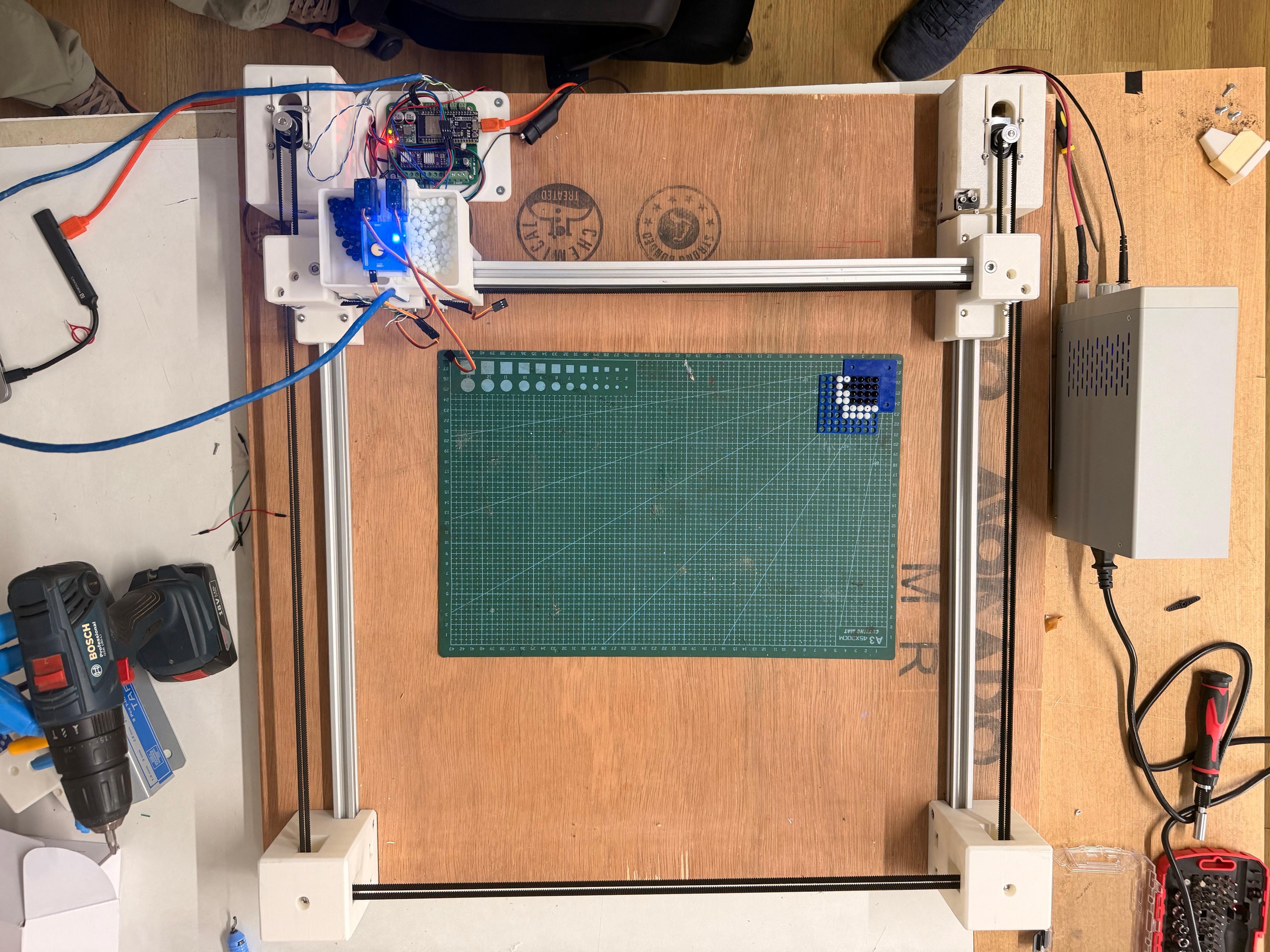
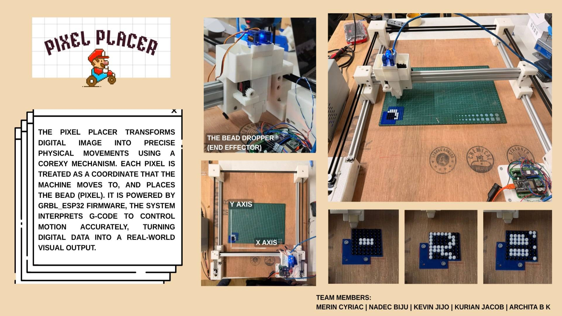
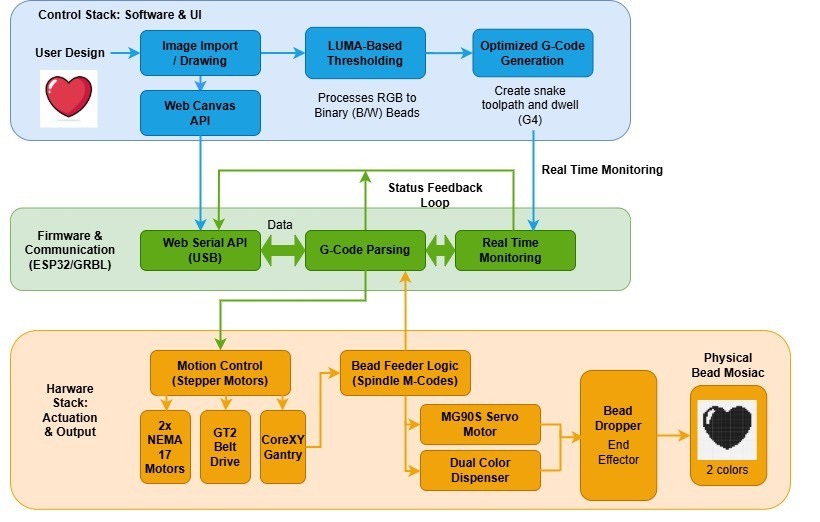
A CoreXY bead-placement machine that translates digital pixel art into physical monochrome art. Machine moves a bead dropper over a perforated acrylic sheet, dropping black or white beads into a grid of holes , one bead per pixel.
Group Assignment:
- design a machine that includes mechanism+actuation+automation+function+user interface
- build mechanical parts and operate it manually
- document group project and your individual contribution
Team
| Member | Role | GitHub |
|---|---|---|
| Nadec Biju | Machine Gantry (CoreXY) | @NB6RULES |
| Kevin J Jijo | End Effector | @mrkubby |
| Merin | Electronics & Documentation | @merinmenamparambil |
| Architha B K | Firmware & Presentation | @architabk618-hue |
| Kurian | Interface & Fabrication | @appukurian |
Concept
Idea was to build a machine that could physically recreate pixel art, retro, grid-based aesthetic of early video game graphics, using real beads on an acrylic substrate. Instead of printing or drawing, machine places beads: each pixel in digital image becomes one physical bead dropped into a hole.
Perforated acrylic sheet acts as fixed grid. CoreXY gantry moves bead dropper to each hole position in sequence, activates correct feeder (black or white), drops one bead, and moves to next. Result: tactile, physical pixel art panel you can hold.
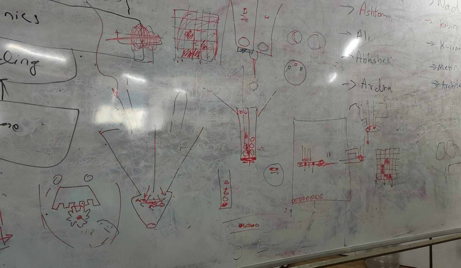 Early concept sketch, machine layout and bead-drop mechanism
Software pipeline: Image → Dithering / Thresholding → Grid Mapping → G-code → ESP32-GRBL → Machine
Design goals: 400 × 400 mm working area, configurable bead resolution (2–10 mm), open-source ESP32 firmware, and a browser-based interface so machine can be driven from any device over Wi-Fi without installing software.
Specifications
| Property | Value |
|---|---|
| Project Name | Pixel Art Machine |
| Machine Type | CoreXY bead-placement CNC |
| Build Area | 400 × 400 mm |
| Bead Diameter | 6.5 mm |
| Resolution | 6.5 mm per pixel (one bead per hole) |
| Color Mode | Monochrome — black & white beads |
| Frame | 2020 aluminium V-slot extrusion |
| Controller | ESP32 + grbl_esp32 |
| Motors | 2× NEMA17 stepper (CoreXY XY axes) |
| Belt | GT2 timing belt, 16T/20T pulleys |
| Substrate | Perforated acrylic sheet |
| Team | Nadec, Kevin, Merin, Architha, Kurian |
| Lab | Fablab KOCHI, Kerala, India |
Machine Breakdown
Core-XY Motion
By Nadec Biju
Motion system uses a CoreXY belt arrangement: two NEMA17 stepper motors mounted at back of frame, each driving a continuous GT2 belt. Both belts connect to same carriage. X motion = same direction; Y motion = opposite direction. This keeps moving mass low and enables fast diagonal moves.
Frame
Frame constructed from 2020 V-slot aluminium extrusion. V-slot wheels on carriage ride in profile grooves, providing smooth linear motion without separate linear rails. Corner brackets and printed motor mounts complete structure.
Key Components
| Component | Specification |
|---|---|
| Motors | 2× NEMA17 stepper |
| Belt | GT2 2 mm pitch timing belt |
| Pulleys | 16T / 20T GT2, 625 bearing idlers at corners |
| Frame | 2020 V-slot aluminium extrusion |
| Carriage | V-slot polycarbonate wheels + eccentric nuts |
| Work area | 400 × 400 mm |
3D Model
Full assembly was designed in SolidWorks. A first-draft 3D model available on Sketchfab:
References
- CoreXY.com — belt routing geometry and kinematics
- Jubilee (Machine Agency) — open-source CoreXY gantry reference
Electronics & Control Board
By Merin
Electronics based on an ESP32 development board running grbl_esp32. Stepper drivers: DRV8825 modules. Power comes from a 12 V supply via a barrel jack.
Bill of Materials — Electronics
| Component | Specification |
|---|---|
| Microcontroller | ESP32 development board |
| Stepper drivers | DRV8825 (×2 for XY) |
| Power supply | 12 V DC |
| Limit switches | ×2 (X, Y) |
| Feeder outputs | M3 (black), M4 (white) via spindle pins |
| Communication | USB serial & Wi-Fi (ESP32 native) |
ESP32's built-in Wi-Fi means G-code can be streamed wirelessly from interface — no USB cable needed during normal operation. NeoPI_Wireless approach used for wireless G-code streaming layer.
Firmware — grbl_esp32
By Architha B K
Machine runs grbl_esp32 by bdring — a port of original GRBL motion controller adapted for ESP32. It handles real-time step generation, acceleration planning, G-code parsing, and Wi-Fi communication out of box.
CoreXY Kinematics
grbl_esp32 supports CoreXY natively. Kinematic transform applied at firmware level — interface sends standard X/Y G-code and firmware resolves it to motor A/B steps:
steps_A = steps_X + steps_Y; // Motor A (left) steps_B = steps_X - steps_Y; // Motor B (right)
G-code Command Reference
| Command | Description |
|---|---|
| G21 | Set units to mm |
| G90 | Absolute positioning |
| G28 | Home all axes |
| G0 Xn Yn F3000 | Rapid move to hole position |
| G4 Pn | Dwell n ms — wait for bead to seat |
| M3 S100 | Black bead feeder ON (spindle CW) |
| M4 S100 | White bead feeder ON (spindle CCW) |
| M5 | Feeder OFF |
| M30 | End of program |
Feeder command only changes when bead color changes — unnecessary M3/M4 transitions skipped to keep G-code compact.
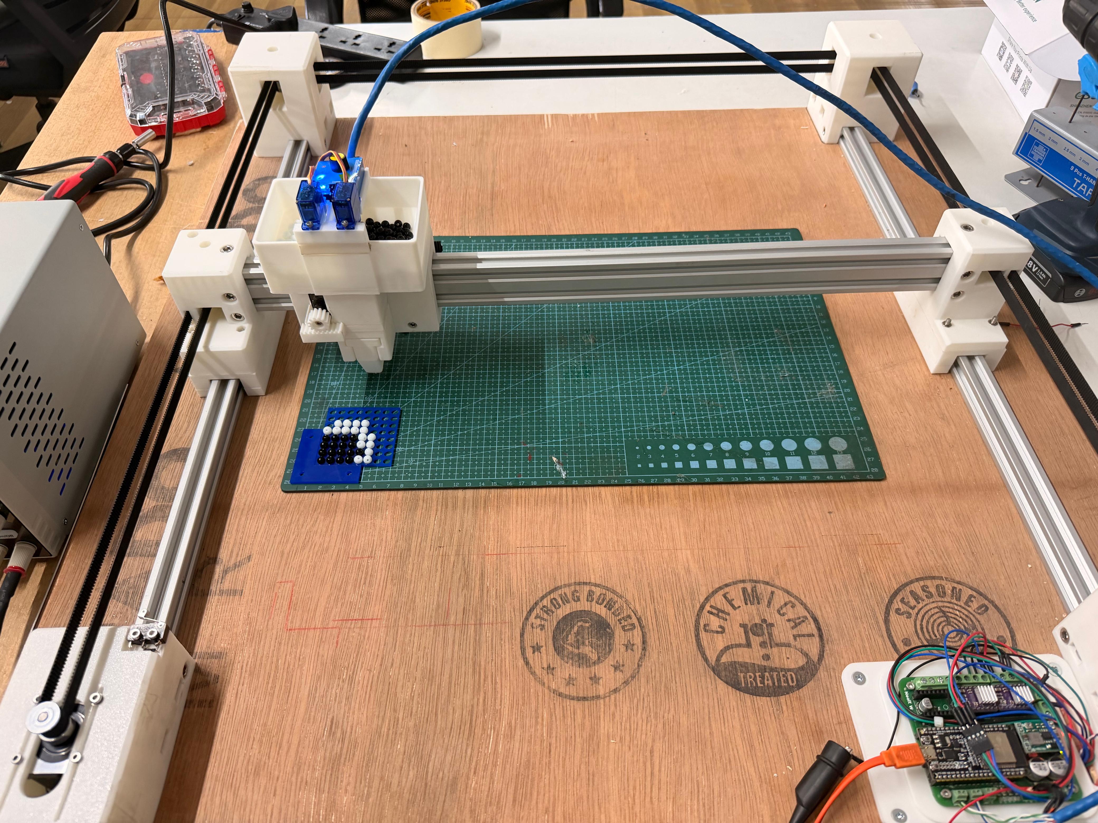
Bead Dropper End Effector
By Kevin J Jijo
End effector: bead dropper mechanism mounted on CoreXY carriage. It holds a hopper of beads (sorted by color) and releases one bead on command when carriage positioned over a hole.
Actuation via a servo or solenoid that gates bead channel. A short dwell (G4 Pn) after each move gives bead time to fall and seat in hole before carriage moves on.
Specifications
| Property | Value |
|---|---|
| Actuation | Servo / solenoid gate |
| Bead diameter | 6.5 mm |
| Bead colors | Black, white (monochrome) |
| Feeder trigger | M3 (black) / M4 (white) G-code commands |
| Substrate | Perforated acrylic sheet, hole pitch = bead size |
| Material | 3D-printed PLA mount + hopper |
Parametric design: bead size and hole pitch configurable — same end effector works with any bead diameter by reprinting channel insert. Interface's bead-size setting must match physical bead used.
Pixel Bead Placer — Web Interface
By Kurian
Kurian built a fully browser-based tool — no installation required. It provides a pixel canvas editor, an image importer, and a G-code generator that outputs GRBL 1.1 / grbl_esp32 compatible code.
Features
- Configurable bead size (1–200 mm) → recalculates grid automatically
- Pen (black) and eraser (white) tools for manual pixel editing
- Image import — any PNG/JPG auto-dithered to the grid resolution
- One-click G-code generation — downloads as bead_art.gcode
- Snake-path toolpath (even rows L→R, odd rows R→L) to minimise travel
- Feeder switching: only emits M3/M4 when color actually changes
G-code Output Structure
G21         ; mm units
G90         ; absolute positioning
G28         ; home

; Row 0  (L→R)
M3 S100         ; black feeder ON
G0 X5.00 Y5.00 F3000
G4 P300
G0 X15.00 Y5.00 F3000
G4 P300
...
M5          ; feeders off
G28         ; return home
M30         ; end of program
Image Pipeline
// Per-pixel luma threshold
luma = 0.299 * R + 0.587 * G + 0.114 * B;
bead = (luma < 128) ? BLACK : WHITE;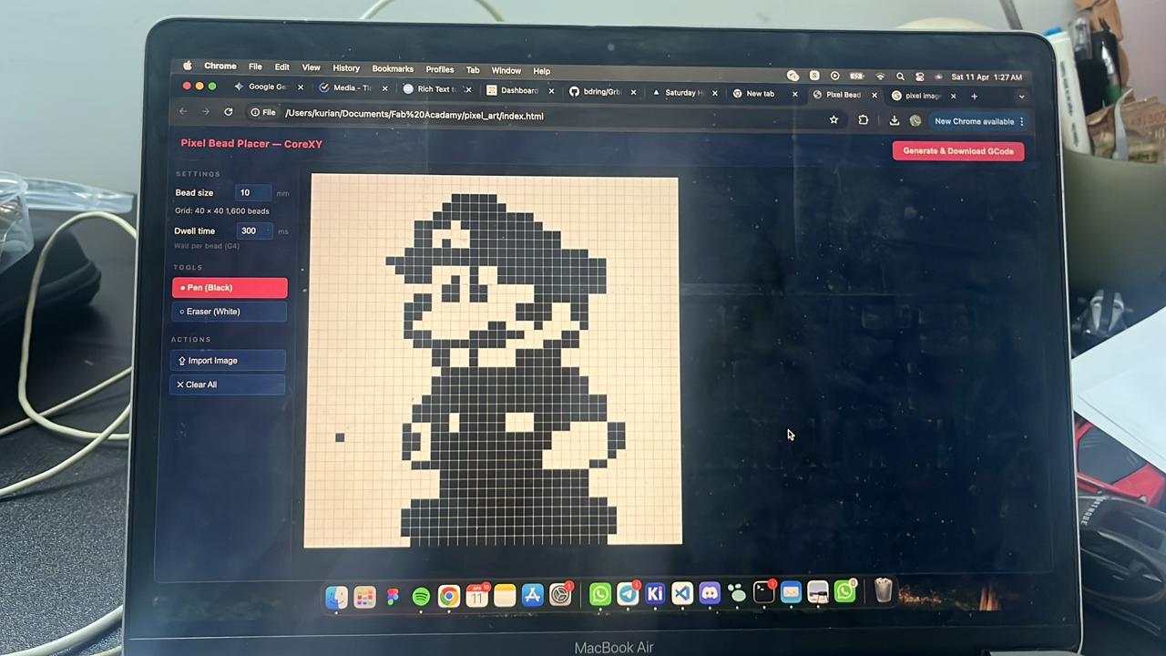
Timeline
| Date | Activity |
|---|---|
| Apr 09 | Initial discussion and team role allocation |
| Apr 10 | Concept sketch, gantry CAD start, interface design, first G-code tests |
| Apr 11 | End effector mechanism design and working structure |
| Apr 12 | End effector parametric sizing (bead measurements), electronics design |
| Apr 13 | G-code / gantry movement testing, firmware bring-up |
| Apr 15 | Fabrication and integration |
| Apr 20–21 | Video editing and presentation |
Github
Repository
Mechanical
Electronics
- KiCad Schematic
- KiCad PCB
- Gerber Files
Firmware
Interface
Pixel Art Machine — Machine Week, Fab Academy 2025 · Fablab KOCHI
Nadec · Kevin · Merin · Architha · Kurian
Kevin J Jijo - End Effector
This week we were tasked with building a machine that incorporated a mechanism powered by an actuation system. The entire system also had to be automated with an application interface for user input. This was a fairly large task to complete individually, so the class was divided into two groups of five students, each group responsible for developing one machine.
After discussing several possible concepts, our group decided to build a pixel art generating machine that recreates images using black and white beads.
Problem Definition
The objective was to design a reliable end effector capable of dispensing individual black and white beads on demand. The mechanism needed to accurately select between two bead colors, prevent jamming, integrate with the automated gantry system, and remain compact, lightweight, and easy to manufacture.
Exploring the Solution Space
Before starting fabrication, several concepts were evaluated for both the dispensing and actuation mechanisms. Different slider designs, dispensing methods, and motion conversion mechanisms were considered, including a Scotch yoke and a rack-and-pinion drive. Early prototypes were used to evaluate these concepts and identify limitations before converging on the final design.
Initial Concept
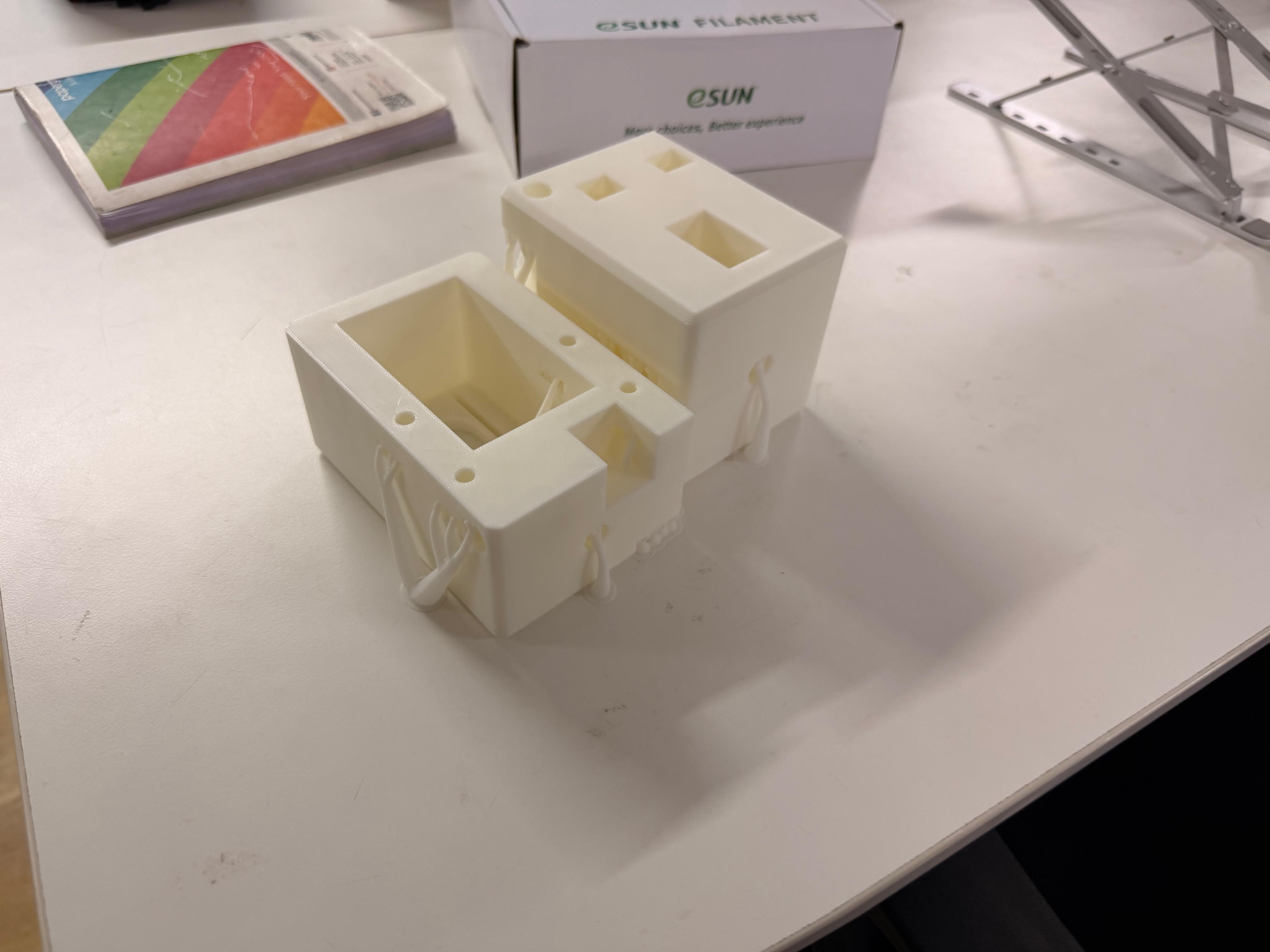
We divided responsibilities among the team members and I was assigned the design and development of the end effector. We discussed multiple approaches for bead dispensing and eventually arrived at the idea of a funnel bucket feeding beads continuously into a slider. The slider height would match exactly the height of a single bead so that only one bead could pass at a time. A single dispensing hole would release either a black or a white bead depending on the slider position. The slider always carries one black bead and one white bead, and the actuation selects which bead is dropped.
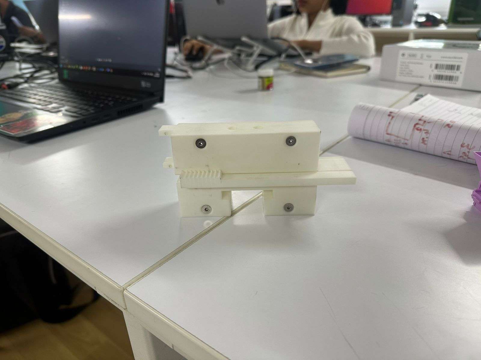
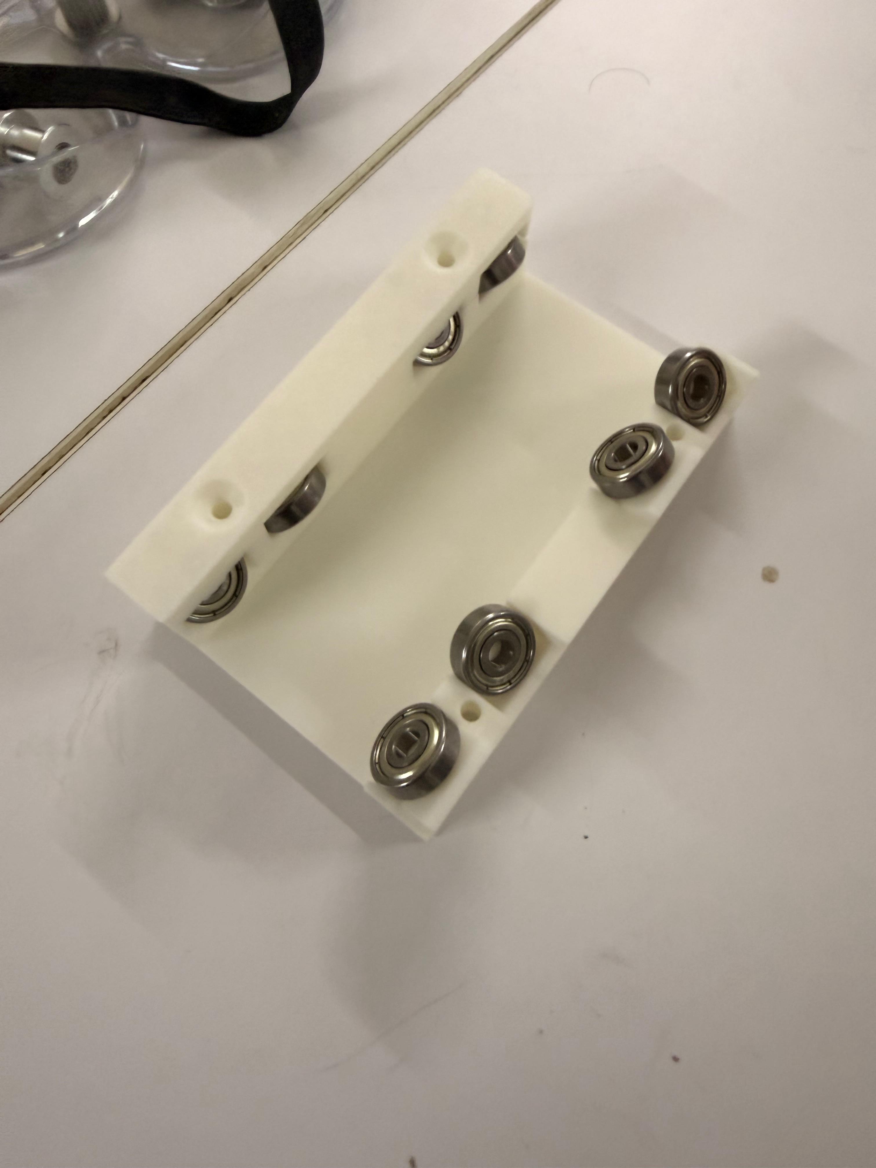
To validate the idea quickly, I built a rudimentary prototype.
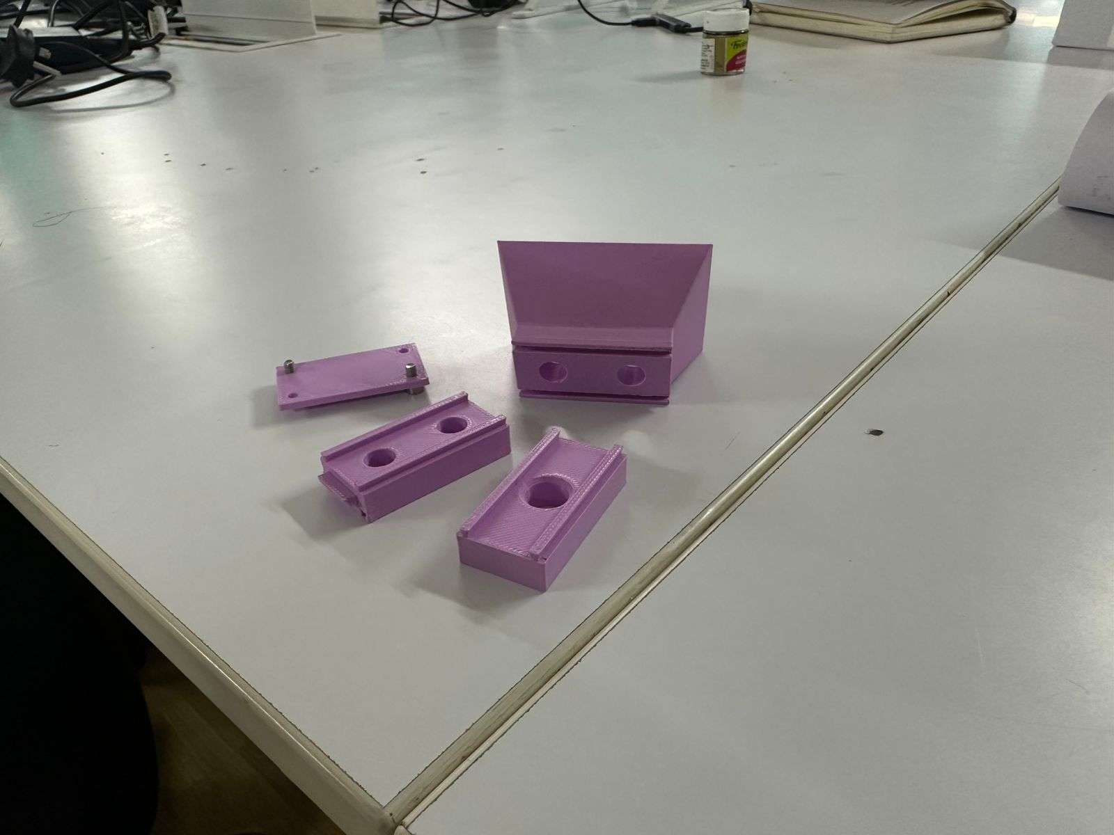
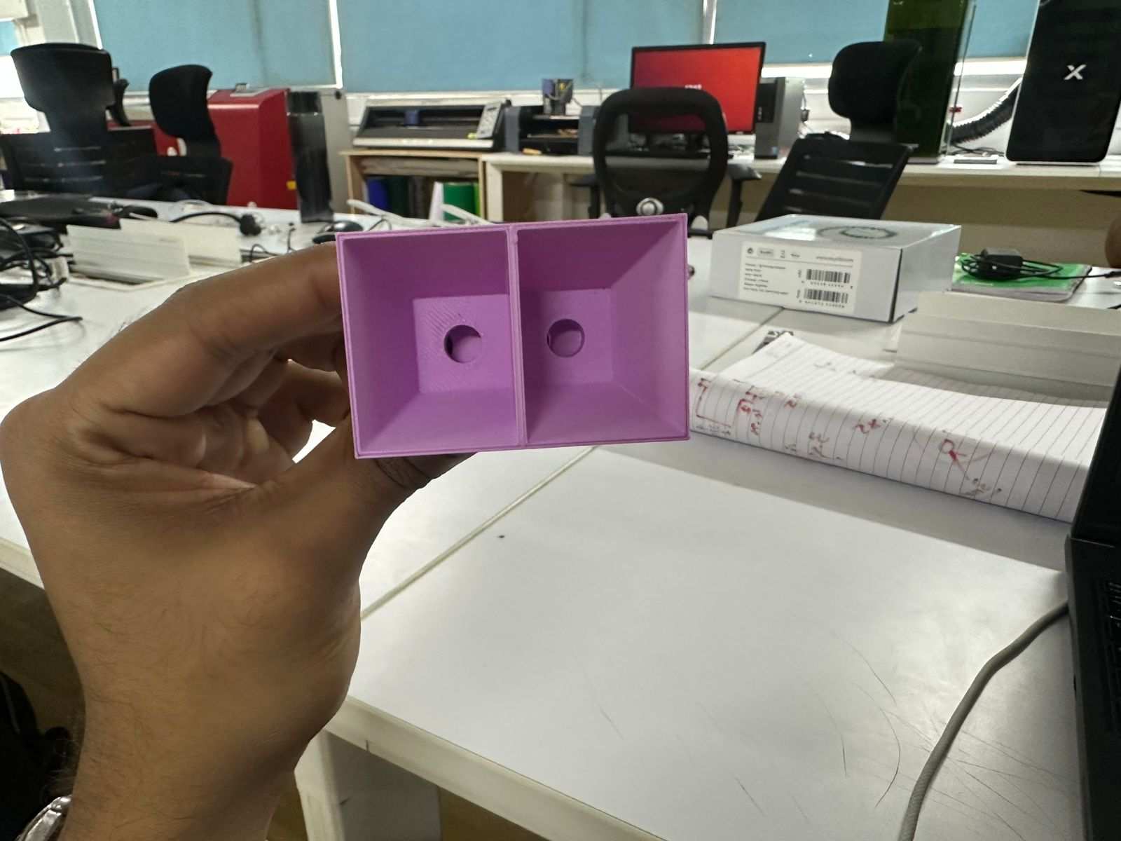
The prototype consisted of four parts: a bucket funnel with a separating wall dividing the black and white bead channels, a slider whose height matched a single bead, a dispensing layer containing one large hole, and a backplate that held all components together.
I implemented a dovetail extrusion as the sliding mechanism.
Once fully assembled, several problems became apparent. The structure lacked stability, the bead height tolerances were inaccurate which caused inconsistent dispensing, and the dovetail slider did not move as smoothly as expected. Despite these shortcomings, the prototype successfully demonstrated that the fundamental concept worked.
Another issue was that the region around the funnel remained flat, allowing beads to accumulate and interrupt flow. Using these observations, I began a redesign.
Selecting the Actuation Mechanism
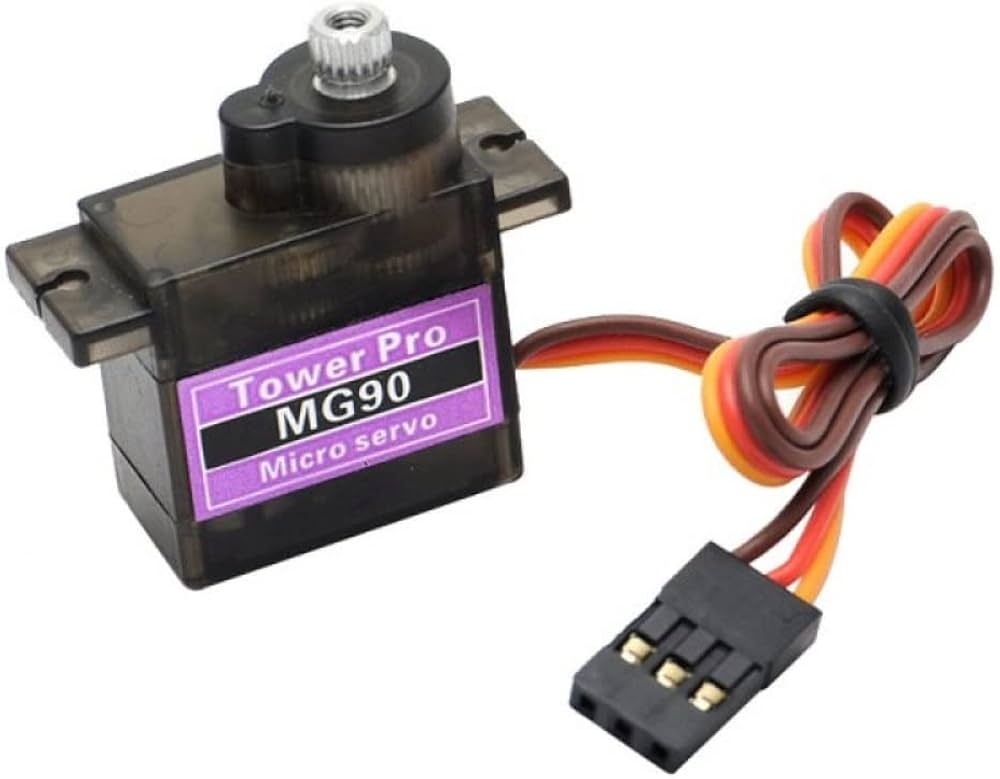
I also needed a method to actuate the slider. I decided to use an MG90S 180° servo motor.
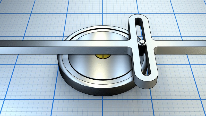
Initially, I considered using a Scotch yoke mechanism to convert the servo rotation into linear slider motion.
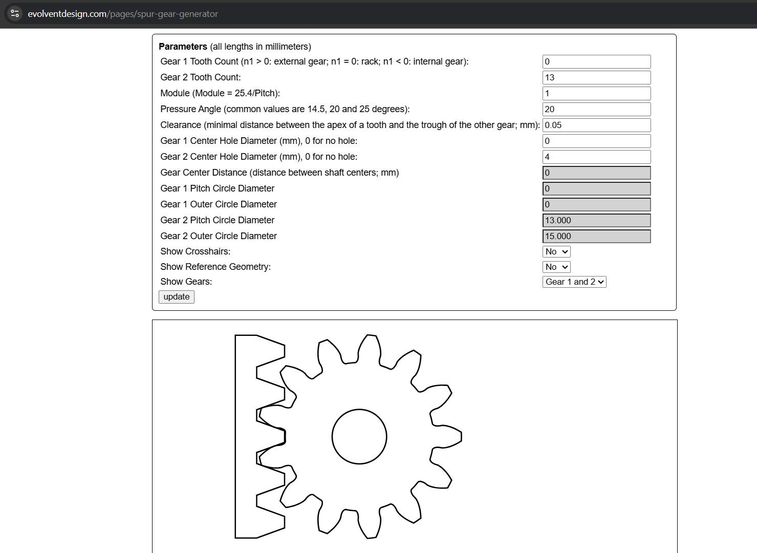
However, due to concerns regarding mechanical complexity and the limited project timeline, I shifted to a rack-and-pinion mechanism. This approach appeared more suitable for controlled linear motion and required fewer experimental iterations.
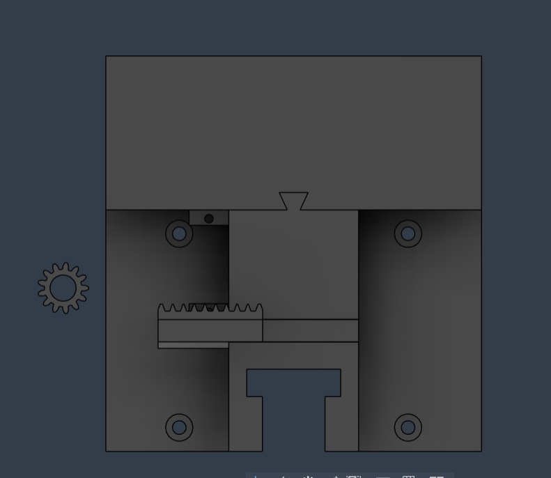
Using the online gear generator at https://evolventdesign.com/pages/spur-gear-generator, I generated a rack-and-pinion profile and exported the DXF file.
I extruded the profile, integrated it into the slider design, and added a mounting location for the servo motor.
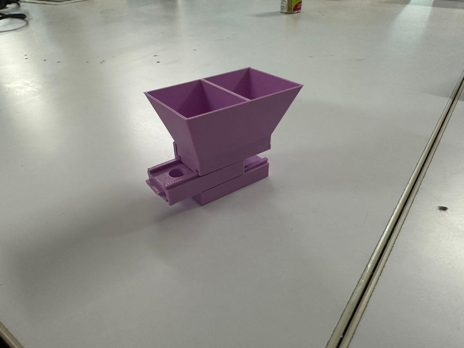
The resulting design was as follows.
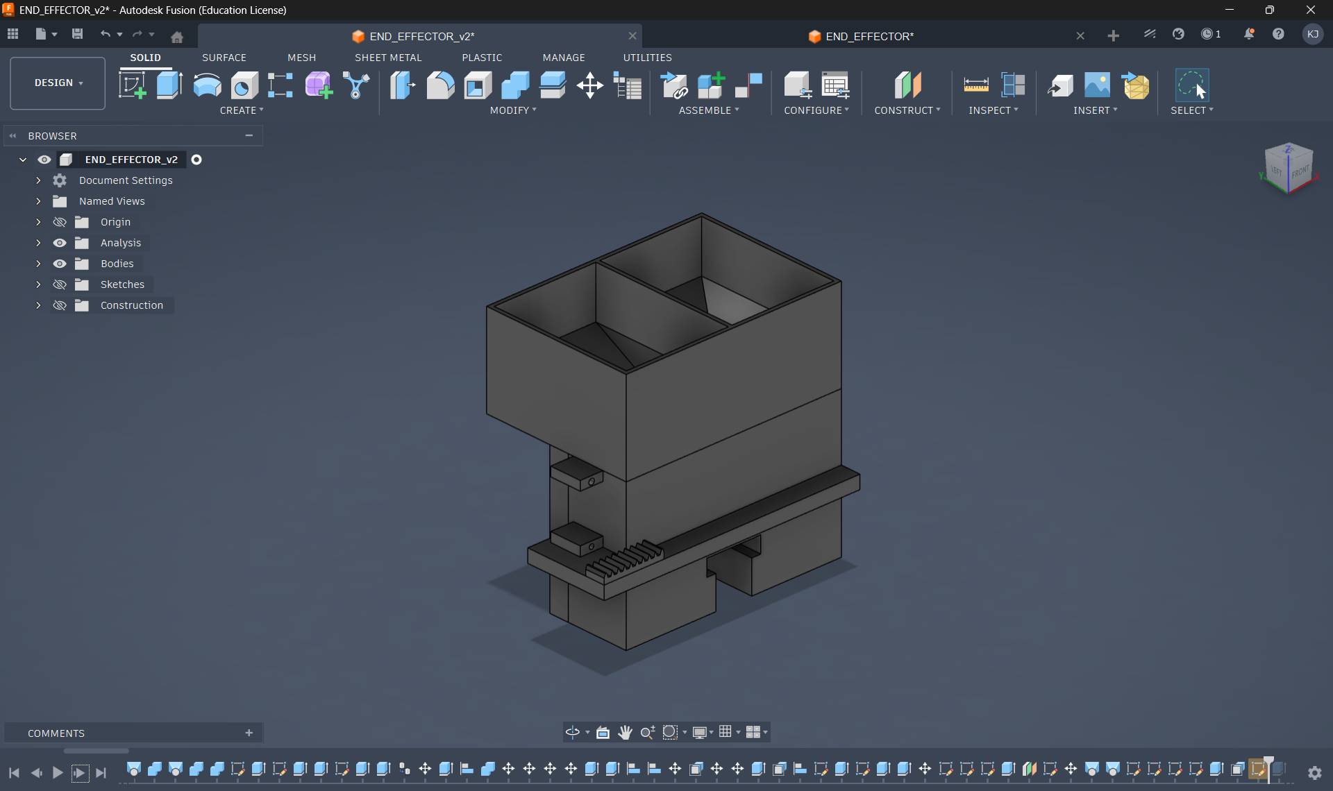
All parts except the bucket were printed. The bucket was intentionally made wide because I planned to match its dimensions to the gantry width. The opening at the bottom was left adjustable to accommodate a nozzle since the final drop height had not yet been determined.
This version also introduced several issues. The dovetail joint again performed poorly because it was undersized and effectively behaved like a loose track. Excess material was used without providing structural benefit. Nevertheless, once the servo was attached, the mechanism functioned and beads could be dispensed successfully.
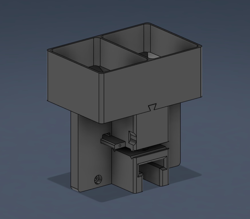
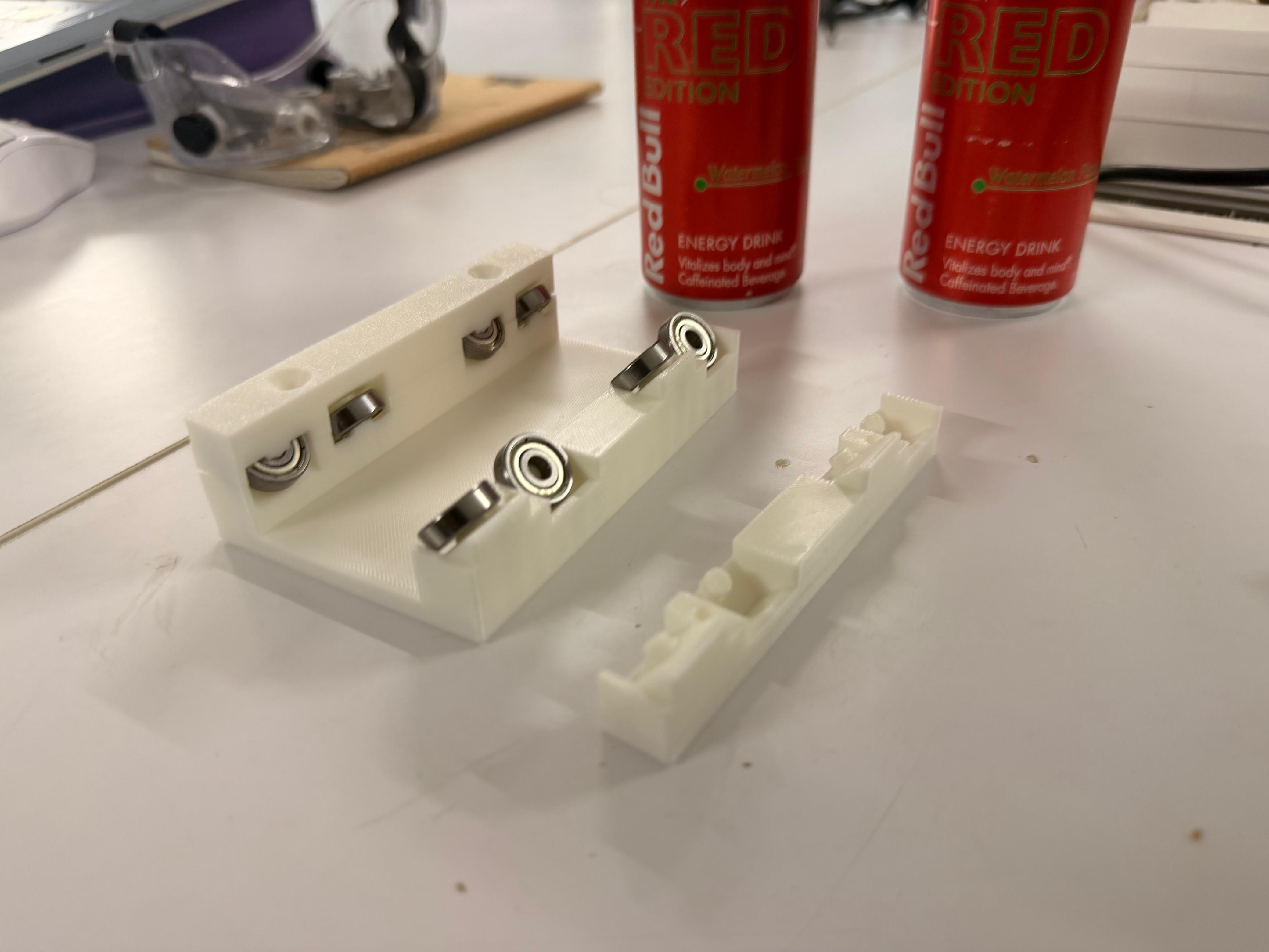
Mechanical Redesign
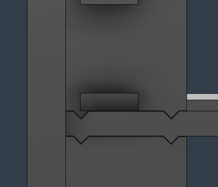
During the redesign, I replaced the sliding joint with a triangular extrusion.
Previously, the backplate existed as a separate component, which meant the slider was not properly clamped. This introduced excessive tolerance and caused the pinion gear to skip teeth during motion. To address this, I redesigned the top, bottom, and backplate as a single integrated component while increasing the backplate thickness for rigidity.
Another limitation was that the earlier end effector depended on mounting holes from the gantry and could not function as an independent module. The redesign aimed to create a standalone end effector assembly.
The new design resulted in significantly smoother motion while also reducing material usage and prioritizing the bead dispensing region.
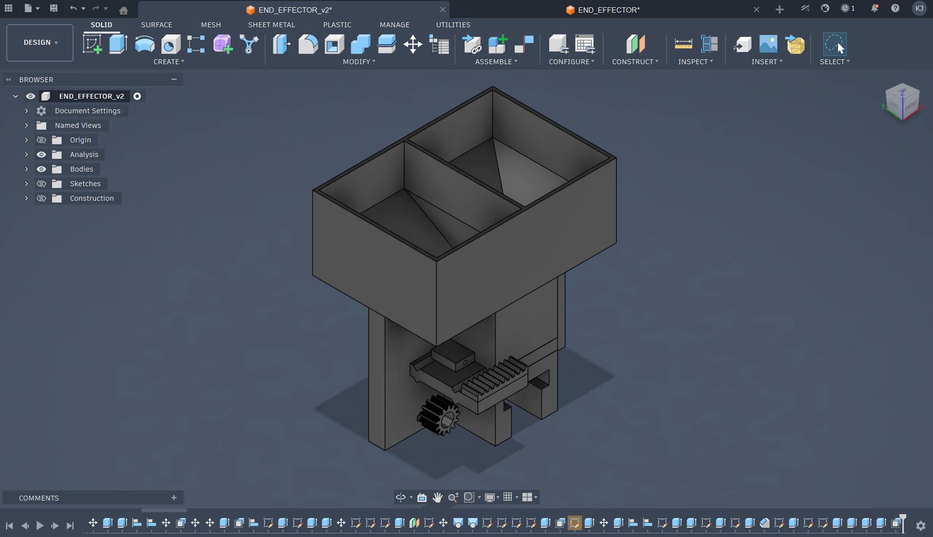
I also introduced a dovetail joint for the bucket, allowing it to slide in and be removed easily for refilling or maintenance.
A first integrated prototype model was produced.
Solving Hopper Clogging
The slider mechanism worked reliably during testing, but a major issue appeared in the bucket hopper. At some point in the funnel geometry, the width became exactly two beads wide. At this location, beads jammed and stopped flowing, a phenomenon known as hopper clogging.
After researching possible solutions, I determined that an agitator was required to maintain continuous bead flow.
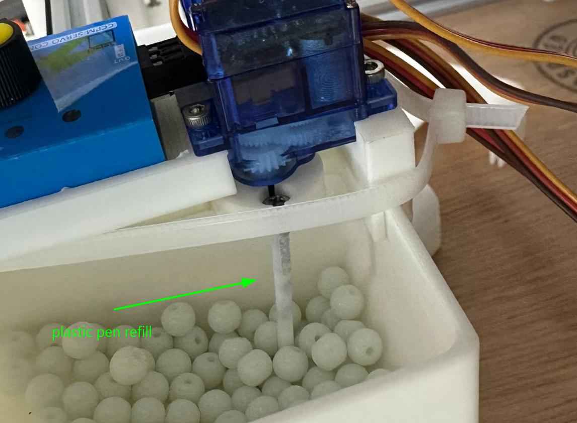
Through experimentation, I discovered that rotating a pen refill around the drop hole prevented clogging and allowed beads to flow consistently.
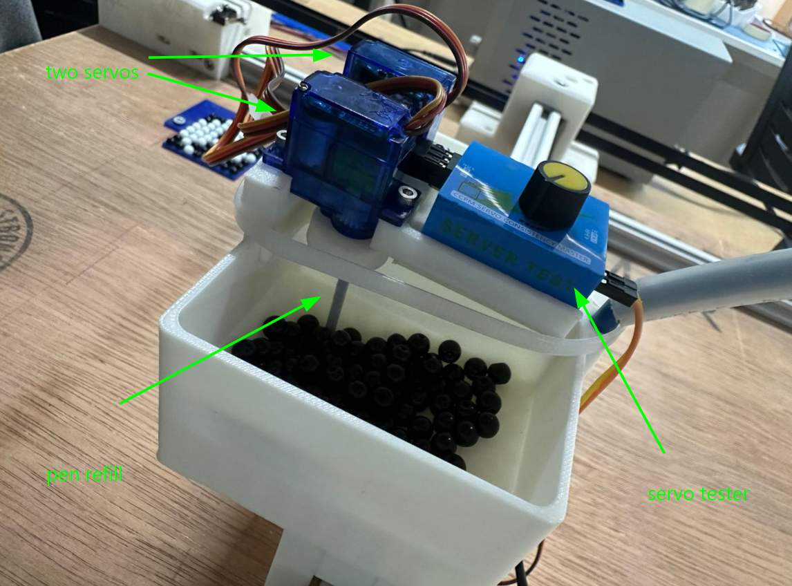
Given the approaching deadline, I implemented a practical solution. Two servos were positioned above the funnel drop holes. Each servo rotated a screw positioned close to the hole, continuously disturbing the bead packing.
I first printed a small test assembly that held a single servo and a joint designed to mount an M3 × 40 mm screw.
This worked, so I completed the design and printed both sides.
To simplify electronics integration, I used an existing servo testing board capable of controlling rotation speed instead of developing a dedicated controller.
During extended testing, the rigidity of the metal screws became a failure point. Beads occasionally became trapped between the screw and the wall, causing the servo to stall. Additionally, the agitation sometimes launched beads outward.
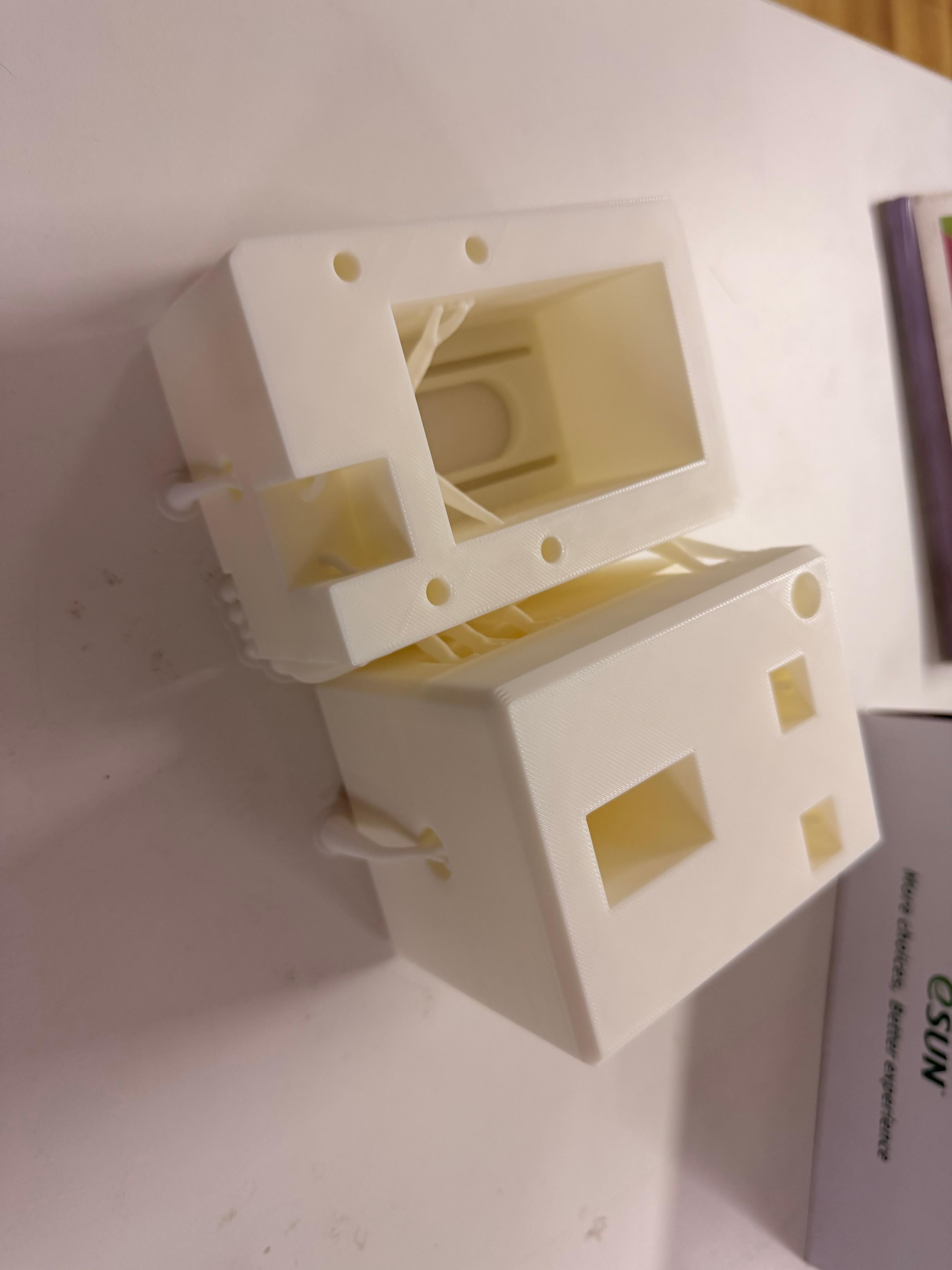
To solve these issues, I replaced the metal screws with trimmed plastic pen refill tubes. Their semi-flexible structure allowed them to deform slightly instead of jamming. I also designed an enclosure around the funnel to prevent beads from being ejected.
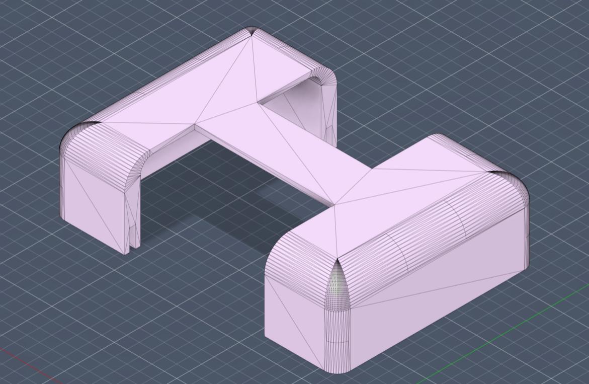
The enclosure also served as a mounting location for the servo testing board.
The completed bead mixer assembly is shown below.
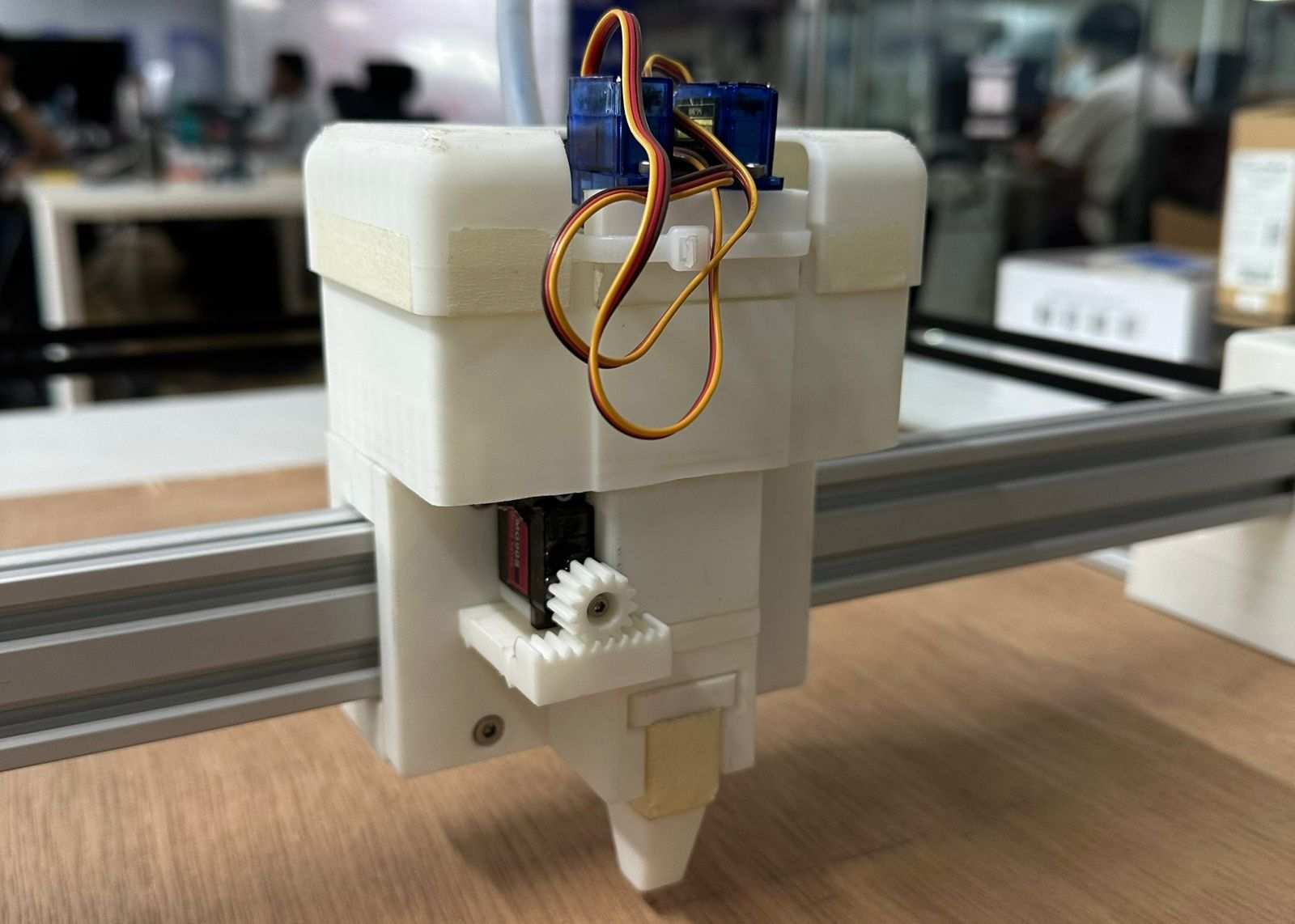
With the enclosure installed, the completed end effector assembly appeared as follows.
Final Result
After final integration and testing, the system successfully dispensed beads to form the letter R.
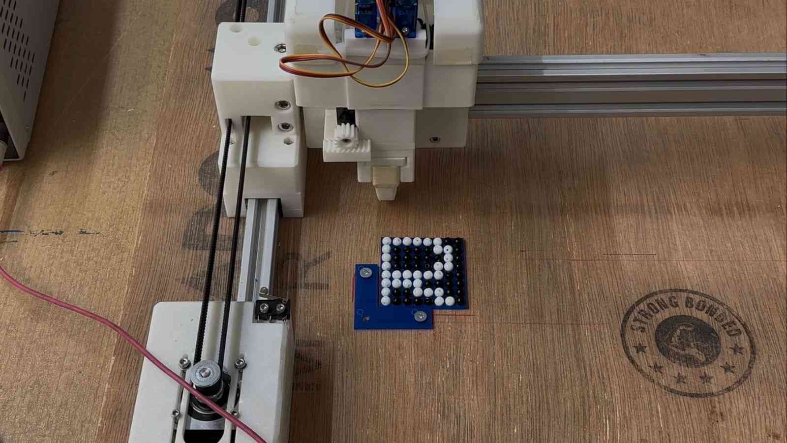
A demonstration of the completed end effector dispensing beads to form the letter P is shown below.
NADEC BIJU - DESIGN AREA
Core XY
I had seen CoreXY machines before, like 3D printers and laser cutters, but only from the outside. I had never taken one apart or built one, so I had no idea how it actually worked on the inside. So I went down a bit of a rabbit hole trying to figure it out.
I started by just Googling "what is CoreXY" and one of the first things that came up was corexy.com, which had a pretty solid breakdown of the whole system.
After that I had a conversation with Claude by Anthropic to get a clearer picture, which I've included below, both as reference and to give credit to the AI that helped me understand it.
By the end of all that, I had a good enough understanding to actually start designing the mechanism for our machine.
AI-generated content below (Claude by Anthropic).
PROMPT : Write a detailed explanation of the CoreXY motion system, including how it works, its advantages, and design considerations.
⚙️ The CoreXY Motion System
CoreXY is a parallel motion system used to drive a tool head across the X and Y plane using two stationary motors and a pair of synchronised belts. It was developed by Ilan Moyer at MIT in 2012 and has since become a popular choice for 3D printers, plotters, and lightweight CNC machines including this project's bead-placement head.
Unlike a conventional Cartesian setup, where one motor rides along the gantry and adds mass to the moving assembly, both CoreXY motors are bolted to the frame and never move. This keeps the moving mass low, which is the core reason the system can run at high speeds and high accelerations without losing accuracy.
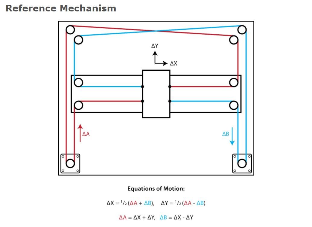
🔄 How It Works
The two motors are linked to the tool head through a pair of belts routed in a characteristic crossed "H" pattern. Neither motor controls a single axis on its own; instead, both motors share the load for every move, and the resulting motion is the combination of how the two motors turn.
Motor A Motor B Resulting Motion Turns same direction Turns same direction Head moves along one axis Turns opposite direction Turns opposite direction Head moves along the other axis Mixed speeds / directions Mixed speeds / directions Diagonal motion The kinematics reduce to two simple equations, where A and B are the rotations of each motor:
ΔX = ½ (ΔA + ΔB)
ΔY = ½ (ΔA − ΔB)
This coupling is handled automatically in firmware (GRBL / FluidNC), so from the host side the machine still accepts standard Cartesian G-code.
✅ Advantages
- Low moving mass motors stay fixed to the frame, so only the head and belts move. This allows high speed and acceleration with reduced ringing/ghosting.
- Z-axis stays independent the XY system is self-contained, making the design well suited to taller builds.
- Symmetric load sharing both motors contribute to every move, distributing torque evenly.
⚠️ Design Considerations
- Belt routing is critical. The two belts must run on different planes so they don't collide, while staying parallel to the axes. Sloppy routing causes binding or crashes.
- Belt tension must be balanced. Uneven or loose tension introduces skew, backlash, and positional error.
- The frame must be square. Any deviation from a true rectangle skews the coordinate system, producing parallelogram-shaped output instead of square geometry.
Design
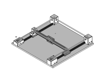
So i started out the design process by creating a rough cad model so that i canconvey my idea to my teammates. I used SolidWorks to create a simple model of the CoreXY mechanism, including the frame, belts, pulleys, and a placeholder for the end effector for bead placement.
I had used solidworks for the design of the machine as i am very familiar with the software.
Please note this was just a design to share the idea so i hadnt bothered to make it very detailed or accurate, the final design ended up being quite different as we had to make adjustments based on the parts we had and the feedback from our teammates.
In this design the pulleys the plane etc are just placeholders and not the actual parts we used, the final design had more accurate representations of the parts we had.
First design
After this deign was made , i had spoken to my team and the intructors Mr Jogin Francis and Mr Sreyas George who gave a lot of expeirnce in building machines and they gave me a lot of feedback on the design and how to improve it. They also helped me understand the limitations of the parts we had and how to work around them.
they had made be realise that the current deign i had in mind for the gantry system ( i had drawn isnpiration from the x axis gantry sustem used by creality ender 3 s1 pro which was a 3d printed i had a lot of experience playing around with) would be too much of an overcomplication and had suggesed a gantry design that was created by jake read https://github.com/jakeread https://uwaterloo.ca/architecture/jake-read which was a much simpler design and would be easier to build.
My Gantry Design
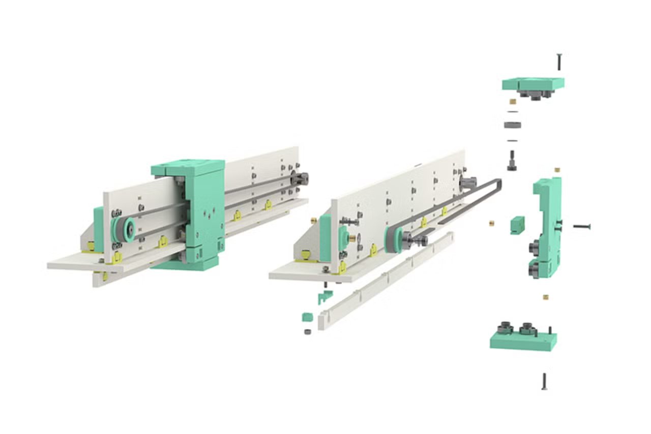
Jake's Gantry Design
After that i had redesigned the gantry system based on jakes design with the help of my instructor Sreyas and then we had a final design that we were happy with and that we could actually build with the parts we had.
Initial design by sreyas based on jakes design
Design Adjusted by me inorder to fit the 20x40 aluminum extrusions we had planned on using.
After the gantry got sorted i moved ahead with the design of the entire machine for which first i drew a sketch with the belt loops 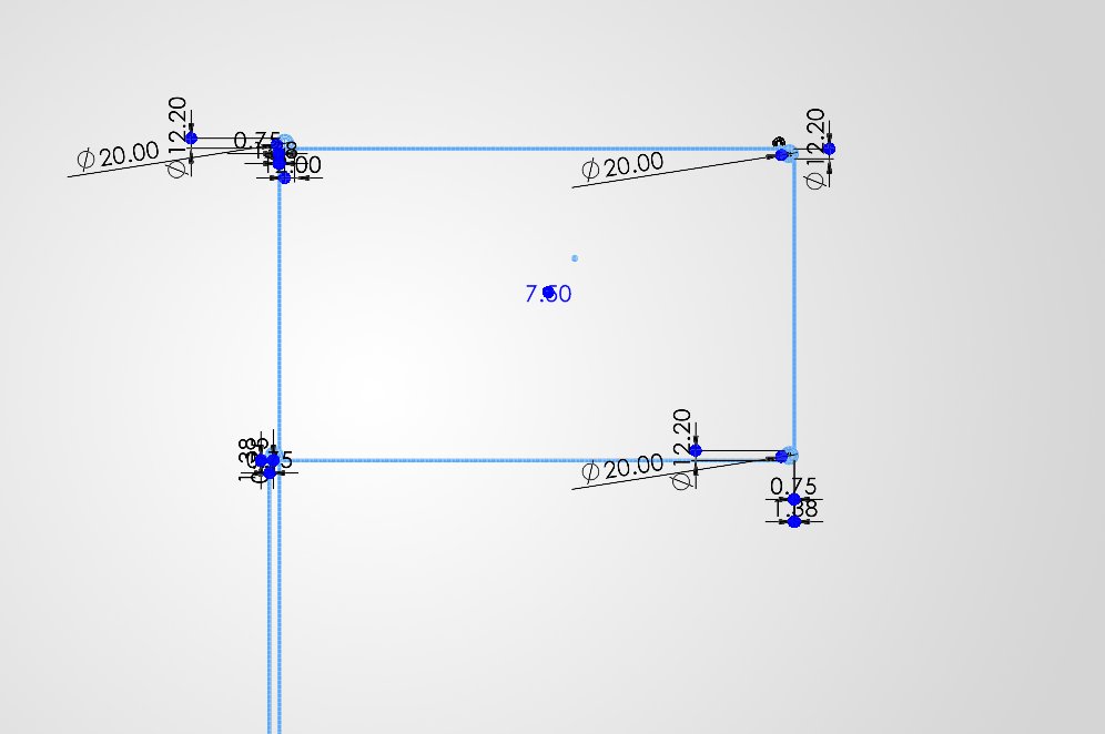
Left belt loop
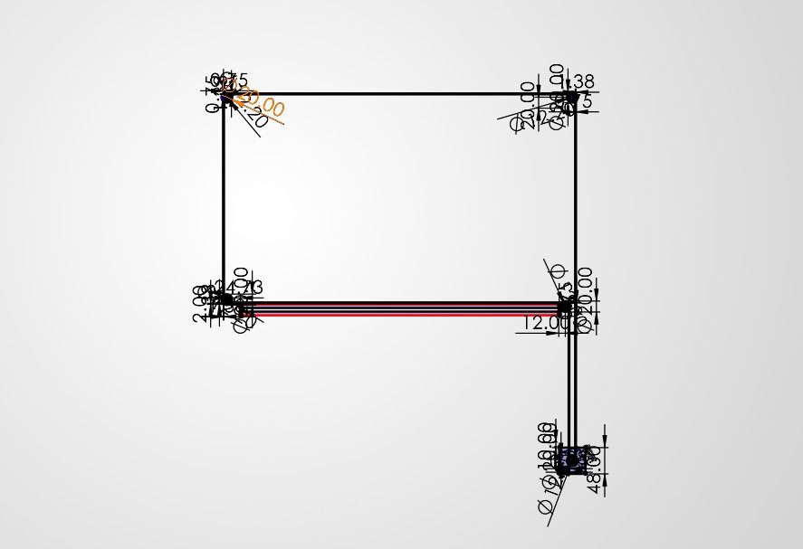
Right belt loop
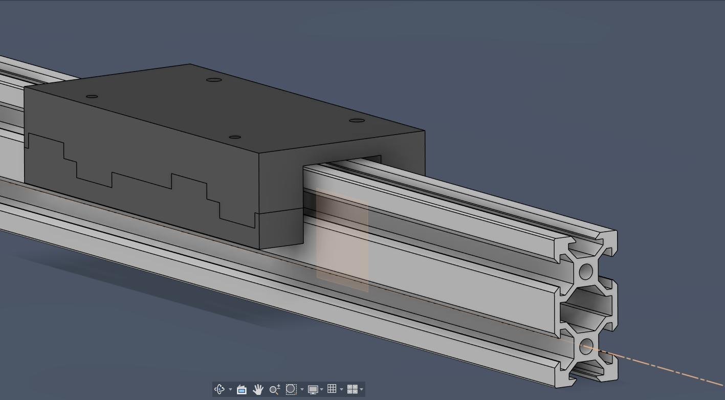
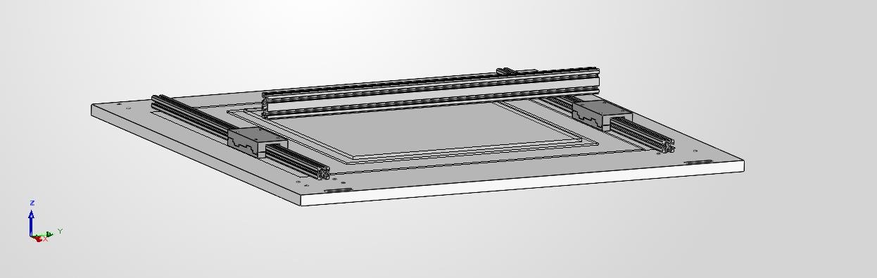
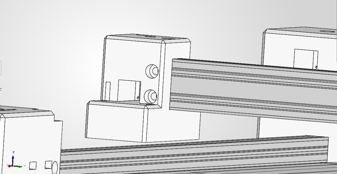
Then i had placed the bottom Base and the aluminum extrusions at the required positions with the gantry which was designed earlier
The height for the x akis gantry placement was decided after discussion with my teammate Kevin Jijo who was in charge of the end effector design and he had told me the height at which the end effector would be able to place the beads properly without any issues.
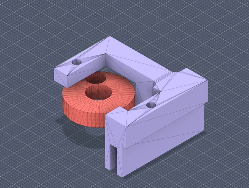
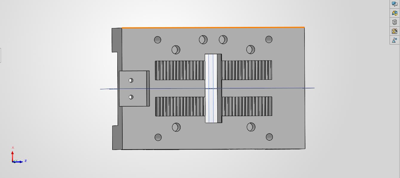
then i moved onto the design of the 4 corner bloacks which would hold the aluminum extrusions in place and the pulley and motors would be mounted on top of these blocks. I had designed these blocks in such a way that they would be easy to print and would also be strong enough to hold the aluminum extrusions in place.
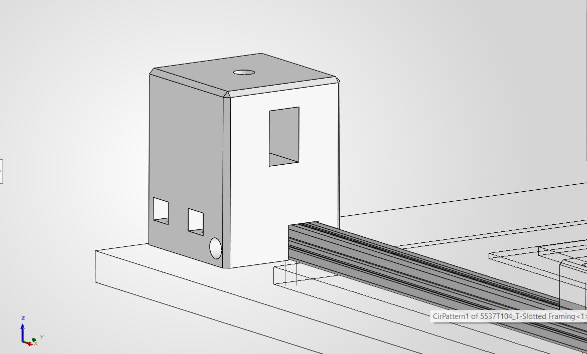
Corner block
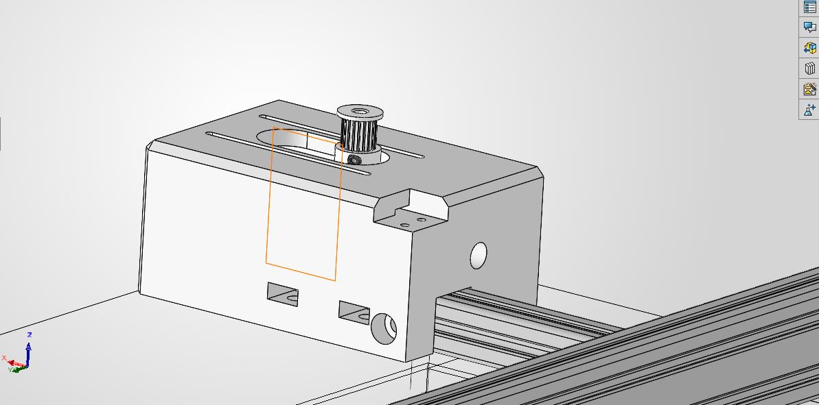
Motor Block
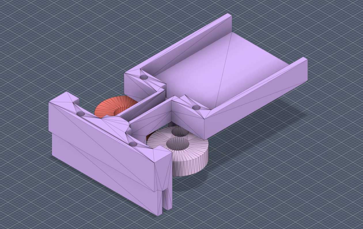
after this i had moved onto the design of the blocks that woud hold the pulleysand the x gantry aluminum extrusions in place .
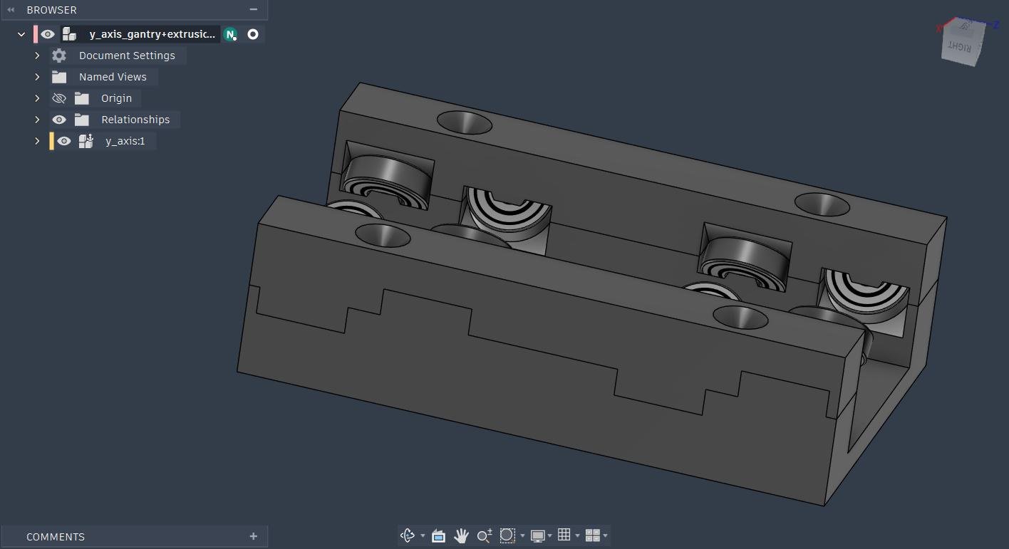
Gantry block
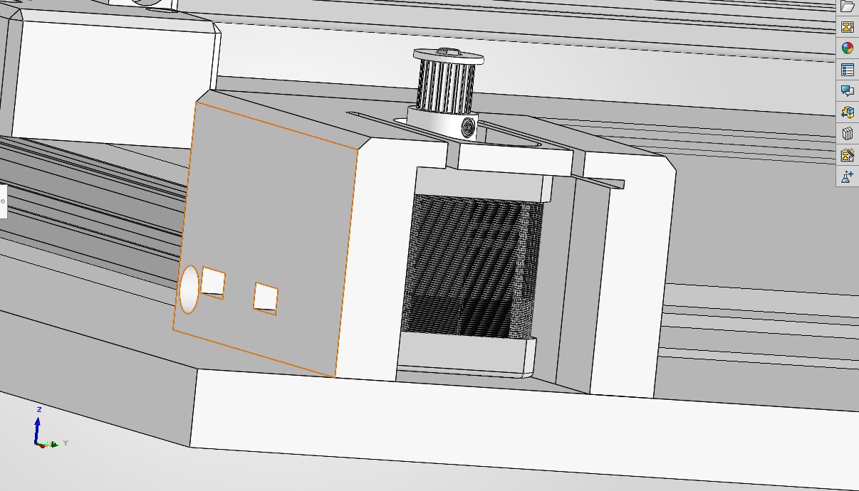
then i had modified the design of the x gantry so that it can be used to tighten the belt of the pulley by tightly pulling the belt and using the ba cap to screw them into place
belt tightening mechanism
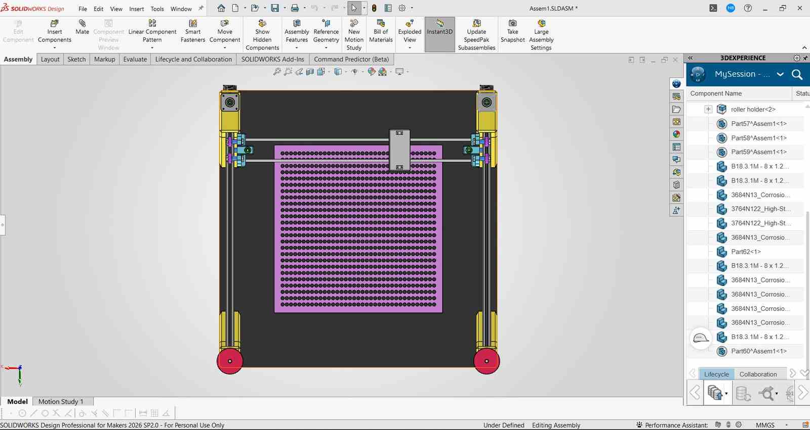
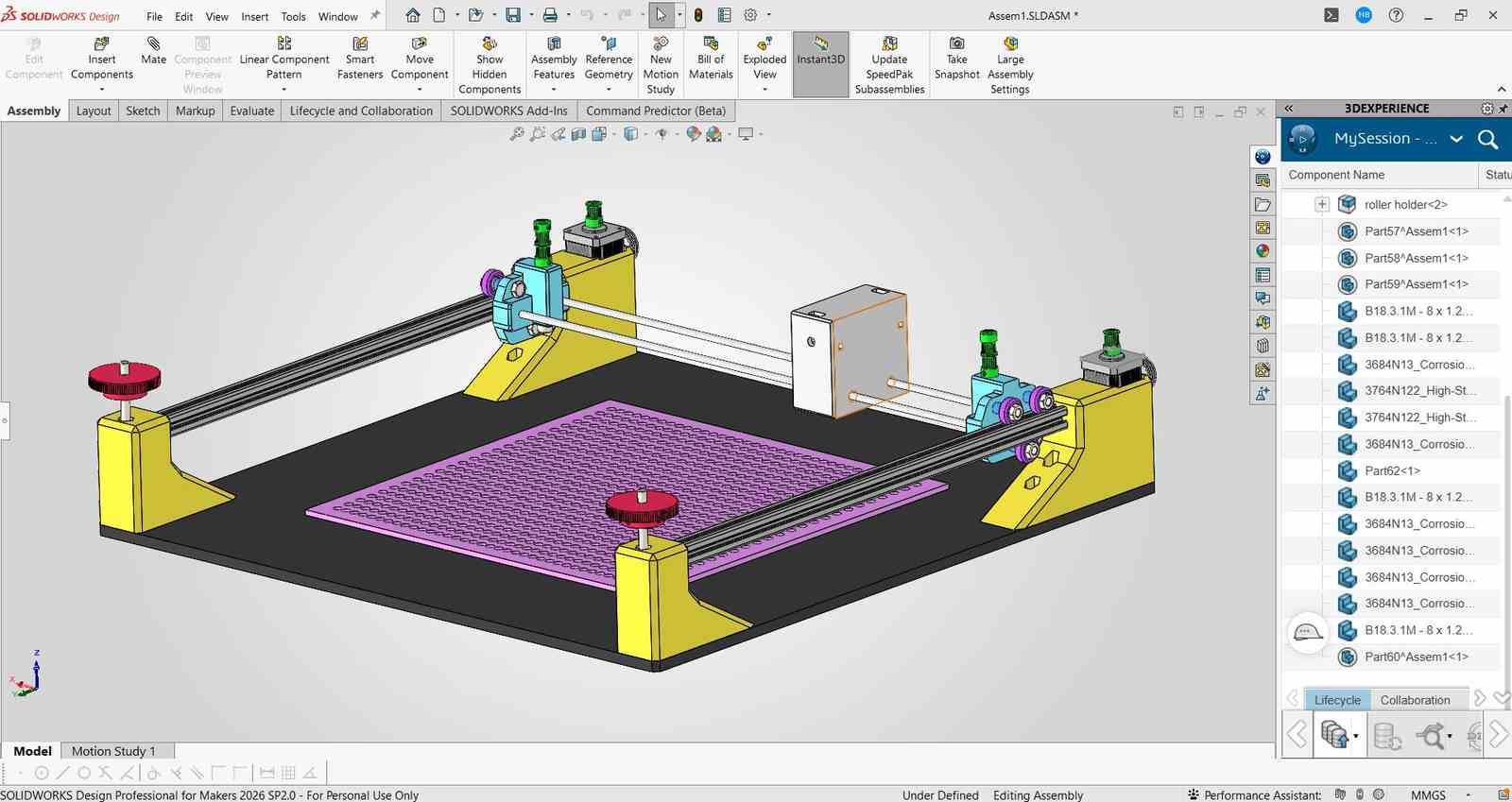
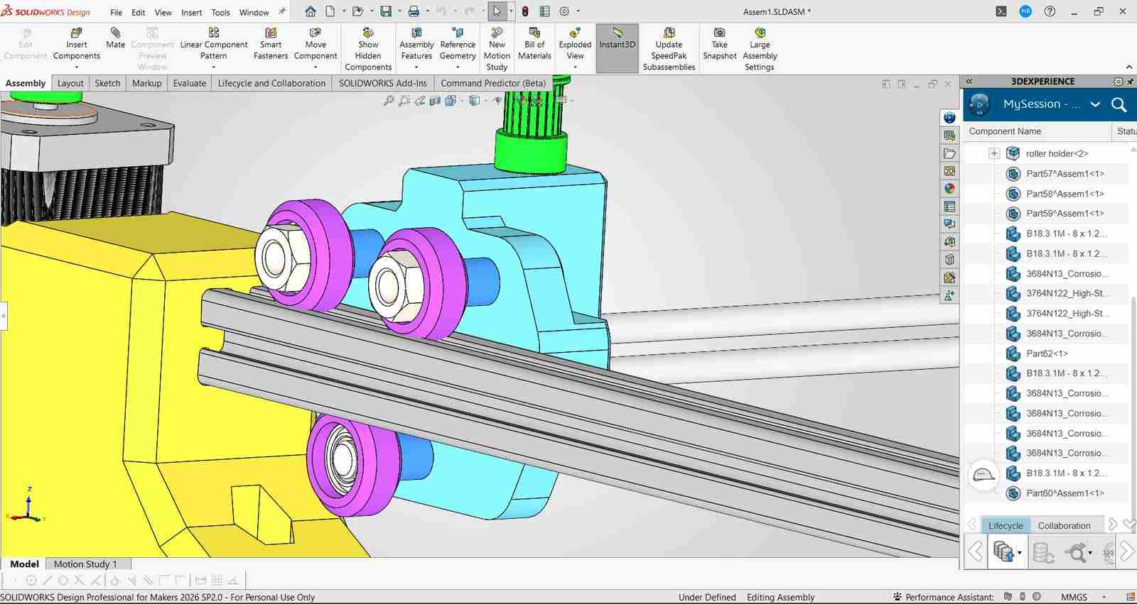
Final CAD Assembly of the CoreXY mechanism with all the parts in place and the belt loops in place.
3D Printing
Gantry System
Corner Blocks
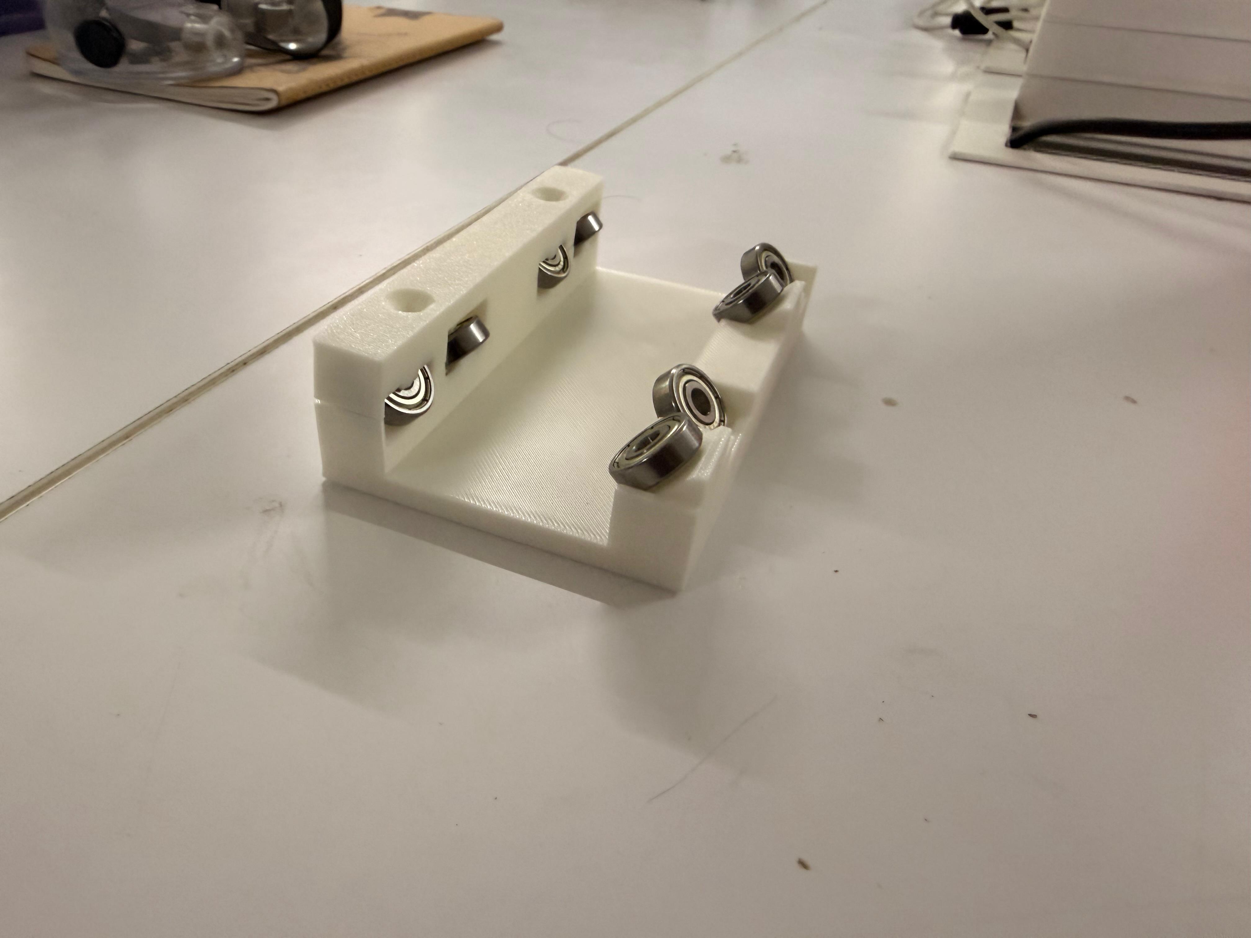
Assembly
Finally Assembled Machine