
Week 7 – Computer controlled machining
Overview
In group assignment we learned about safety measures. We made a jig to test fit. We learned to operate shopbot cnc machine, its speeds, feeds, material and toolpaths.Key aspects of safety training include using Personal Protective Equipment (PPE), following safe behavior practices, conducting pre-operation checks, and adhering to machine operation guidelines. Maintaining a clean workspace, preparing for emergencies, and continuously improving safety procedures further contribute to a secure and efficient working environment. 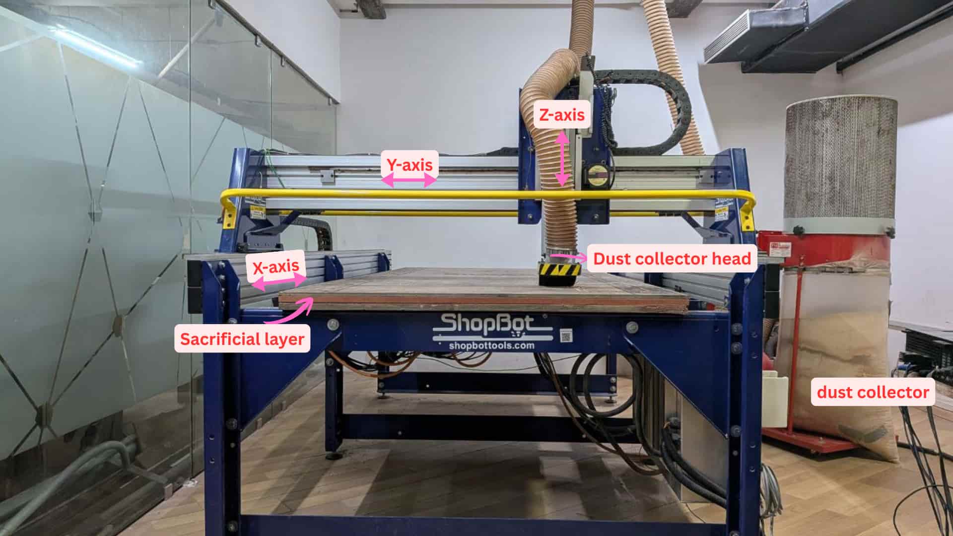
ShopBot CNC Router Safety Guidelines

Read carefully before operating the machine
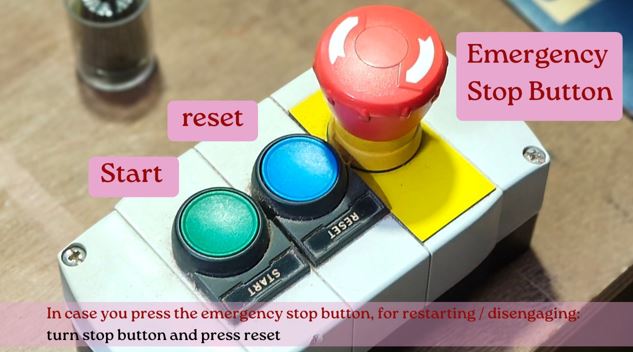
⚠️ EMERGENCY STOP:
Press SPACEBAR or the physical STOP button to immediately halt all movement.
Know where both are before you begin.
1. Personal Safety Precautions
1.1 Personal Protective Equipment (PPE)
- Wear safety glasses at all times to protect against flying debris.
- Use hearing protection (earplugs or earmuffs) when the router or spindle is running.
- Wear enclosed, non-slip footwear. No sandals or open-toed shoes.
- Use cut-resistant gloves when handling sharp material, but remove them before operating rotating machinery.
- Wear a dust mask or respirator. Fine wood dust is a serious long-term health hazard.
- No loose clothing, jewellery, or accessories. Tie back long hair before approaching the tool.
1.2 Safe Behaviour at the Machine
- Stay focused. Never operate the ShopBot while tired, distracted, or under the influence of any substance.
- Put your phone away. No calls, messages, or devices while the machine is running.
- Keep hands clear of the cutting area at all times.
- Never reach into the work zone while the spindle is moving.
- Maintain a safe distance from all rotating components.
- Stand behind a protective screen where possible.
- Warn others in the workshop before starting the machine.
- Stand within reach of the keyboard or STOP button, but clear of the cutting path.
2. Machine Safety
Source:
https://shopbottools.com/wp-content/uploads/2024/01/SBG-00142-User-Guide-20150317.pdf
2.1 Pre-Operation Checks
- Read the ShopBot manual and any router or spindle manual before first use.
- Practice all movements in the control software before activating the router or spindle.
- Inspect bits and blades for wear, cracks, or damage.
- Do not use damaged tools.
- Turn off the router before loading, repositioning, or adjusting any workpiece.
- Unplug the power tool when changing bits to prevent accidental activation.
- Confirm the work surface is clean and the dust skirt is correctly positioned.
- Verify the emergency stop button is functional and within easy reach.
2.2 During Operation
- Secure all materials firmly using clamps or a vacuum hold-down.
- Unsecured material can become a projectile.
- Secure cutouts and offcuts, not just the main sheet.
- Do a dry run (no material) to verify toolpaths before the real cut.
- Never leave the machine unattended while running.
- Let the spindle come to a full stop before making any adjustments or collecting the finished piece.
3. Workshop Safety Measures
3.1 Housekeeping
- Keep floors clear of sawdust and offcuts.
- Use dust collection while cutting.
- Ensure proper ventilation to reduce airborne particles.
- Store tools and materials in their designated areas.
- Clutter causes accidents.
- Do not use the machine bed as a general work surface.
3.2 Fire & First Aid
- Keep a fire extinguisher in a clearly marked, accessible location.
- Maintain a stocked first-aid kit nearby.
- Ensure all users know emergency exits and the location of safety equipment.
4. Continuous Safety Improvement
- Conduct routine inspections of the ShopBot and related equipment.
- Participate in safety training and periodic drills.
- Report potential hazards or unsafe conditions immediately.
- Encourage open communication about near-misses so lessons can be shared.
- Continuously improve procedures based on real-world feedback.
Further Reading
http://www.popularmechanics.com/home/skills/yale-students-tragic-death-prompts-a-shop-safety-review
CNC Machine
Computer Numerical Control (CNC) is an automated manufacturing technology that controls machine tools such as lathes, milling machines, drills, and routers using a computer. CNC technology has significantly transformed modern manufacturing by automating machining processes, improving production efficiency, and enabling the fabrication of complex geometries with high precision and repeatability.
The term CNC stands for Computer Numerical Control, which refers to the use of computer systems to control machining tools during manufacturing. CNC machines operate based on pre-programmed instructions and numerical codes (such as G-code) that define the tool movements, speeds, and machining operations. These instructions guide the machine to perform tasks such as cutting, drilling, milling, or shaping materials like metal, wood, or plastic according to the specified design. As a result, CNC machines can produce accurate parts consistently without requiring continuous manual operation.
A CNC machine is a computer-controlled manufacturing tool used for the fabrication of various parts and products. These machines can perform operations such as cutting, milling, drilling, engraving, and shaping materials with high precision. CNC machines are widely used in modern manufacturing because they automate machining processes, reducing the need for manual intervention while improving accuracy, repeatability, and production efficiency.
CNC machines operate by executing pre-programmed instructions generated through computer software. Unlike conventional machines that rely on manual control using hand levers or wheels, CNC machines follow a numerical control language, primarily G-code and M-code. These codes provide precise commands to the machine, specifying parameters such as tool position, feed rate, spindle speed, and movement coordinates. By following these programmed instructions, CNC machines can produce complex parts consistently and with a high level of precision. 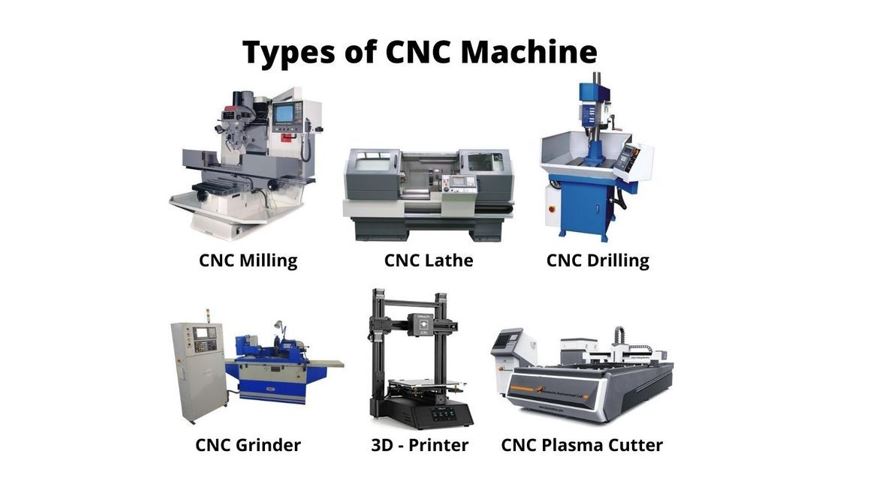
Image Source: https://newindscorp.com/what-are-different-types-of-cnc-machining
Common types of CNC machines include the following:
- CNC Lathes: Primarily used for turning operations, where the workpiece rotates while a cutting tool shapes the material.
- CNC Milling Machines (CNC Mills): Used for cutting, drilling, slotting, and shaping materials using rotating cutting tools.
- CNC Plasma Cutters: Designed for cutting electrically conductive metals by using a high-temperature plasma torch.
- CNC Routers: Commonly used for cutting, engraving, and carving materials such as wood, plastics, composites, and sometimes soft metals.
- 3D Printers: Additive manufacturing machines that create objects by building material layer by layer based on a digital model.
We used the laser cutting machine in Week 3. The next step after that is Computer Controlled Machining.
A CNC (Computer Numerical Control) tool is used in both prototyping and full production for cutting, carving, machining, and milling a variety of materials, including wood, MDF, plastics, foam, and non-ferrous metals such as aluminum.
(Source: https://shopbottools.com/about/what-is-cnc/)
The model can first be designed using CAD software. The design is then exported as a DXF file, arranged on the stock material. After that, VCarve (a CAM software) is used to generate the toolpath and to set the machining parameters that the machine will follow.
Stock refers to the raw material that will be cut. This can include plywood, MDF, HDF, particle board, OSB (Oriented Strand Board), or rubber wood.
There are different types of CNC cutting machines:
- CNC Mill – The stock remains stationary, and the cutting tool rotates to machine the material.
- CNC Lathe – The stock rotates, while the cutting tool may remain stationary or move depending on the operation.
Some machines also have ATC (Automatic Tool Change), which allows the machine to automatically change tools during the machining process.
ShopBot (https://shopbottools.com/)
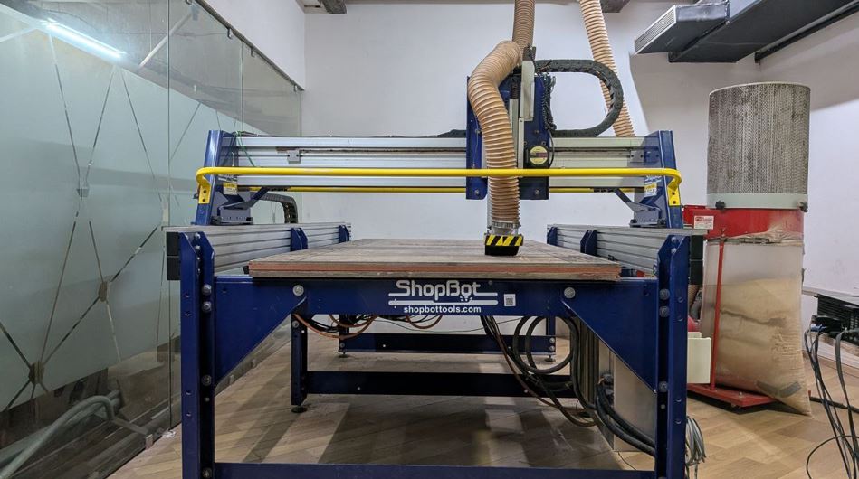
Shopbot is a CNC milling machine.
With this machine, we can engrave and cut materials. The machine moves in three axes:
- X-axis – the longest side of the machine
- Y-axis – the shortest side
- Z-axis – the vertical movement where the tool moves up and down
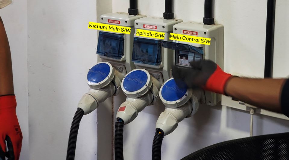
The cutting tool is placed in the center of the spindle, and a vacuum system surrounds it to collect the dust generated during cutting.
Tooling
The bit is the part of the machine that comes in contact with the stock.
Unlike a nail, which simply punctures into a material, a CNC bit rotates along an axis. As it rotates and cuts into the material, the removed material comes out through the flutes in the bit.
We can understand the number of flutes by looking at the bit while holding the tip facing towards us.
Single flute – This is usually used for softer materials.
Multi-flute – This can have more than one flute and is generally used for harder materials.
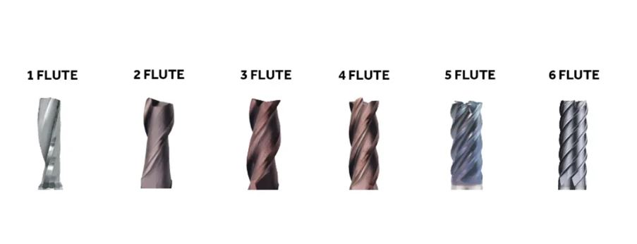
source: https://www.jat-carbide.com/what-edges-and-types-of-end-mills-are-there/
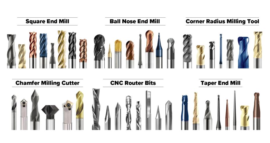
source https://www.jat-carbide.com/it/what-edges-and-types-of-end-mills-are-there/
flat end mill/ square end mill: this is the common cutting tool, cuts through hard surfaces,90 degree cuts.
Types of CNC Cutting Tools
Drilling – The bit moves up and down to create a hole in the material.
Grooving – This is used for engraving. It does not drill or fully cut through the material.
Milling – This is used to cut and create holes, where the side of the bit also participates in the cutting process.
Spotting – This is used to mark spots so that we can manually drill screws later to hold the stock in place or keep it flat.
Long end tools – These are used for drilling or milling into thicker materials that cannot be reached by regular bits.
Coatings:
The bits are made of different materials, sometimes they are coated with different materials.
Coating is added to reduce the wear and tear and increase the life of the tool.
Carbide bit – this is dark in color.
Ceramic coat – this bit lasts longer and is expensive.
High speed steel – this is a common tool material used for milling bits and cutting tools.
Types of milling
Up milling / conventional milling:
In up milling, the movement of the arm of the machine and the bit rotation are in opposite directions.
The bit removes the material gradually.
The chips formed go from thin chips to thicker chips.
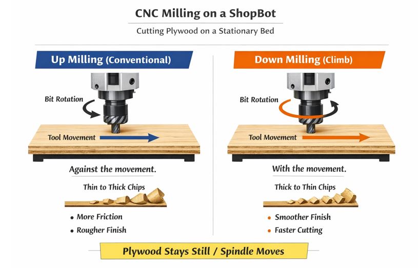
prompt: explain up milling and down milling in simple words to understand, i am confused on how up milling works when the plywood laid on the shopbot is stationery. reply prompt by chatgpt: If you want, I can also show a super clear plywood + ShopBot diagram that makes this click instantly (most students understand it in 10 seconds).
Down millling/ Climb the movement of the arm of the machine and the bit rotation are in same direction. The bit removes the material in chunks and then gradually.
CNC Jig Test
To test the CNC fitting, we designed a jig model in Fusion 360.
Before designing, we measured the material thickness at different points and found the average thickness to be about 11.3 mm.
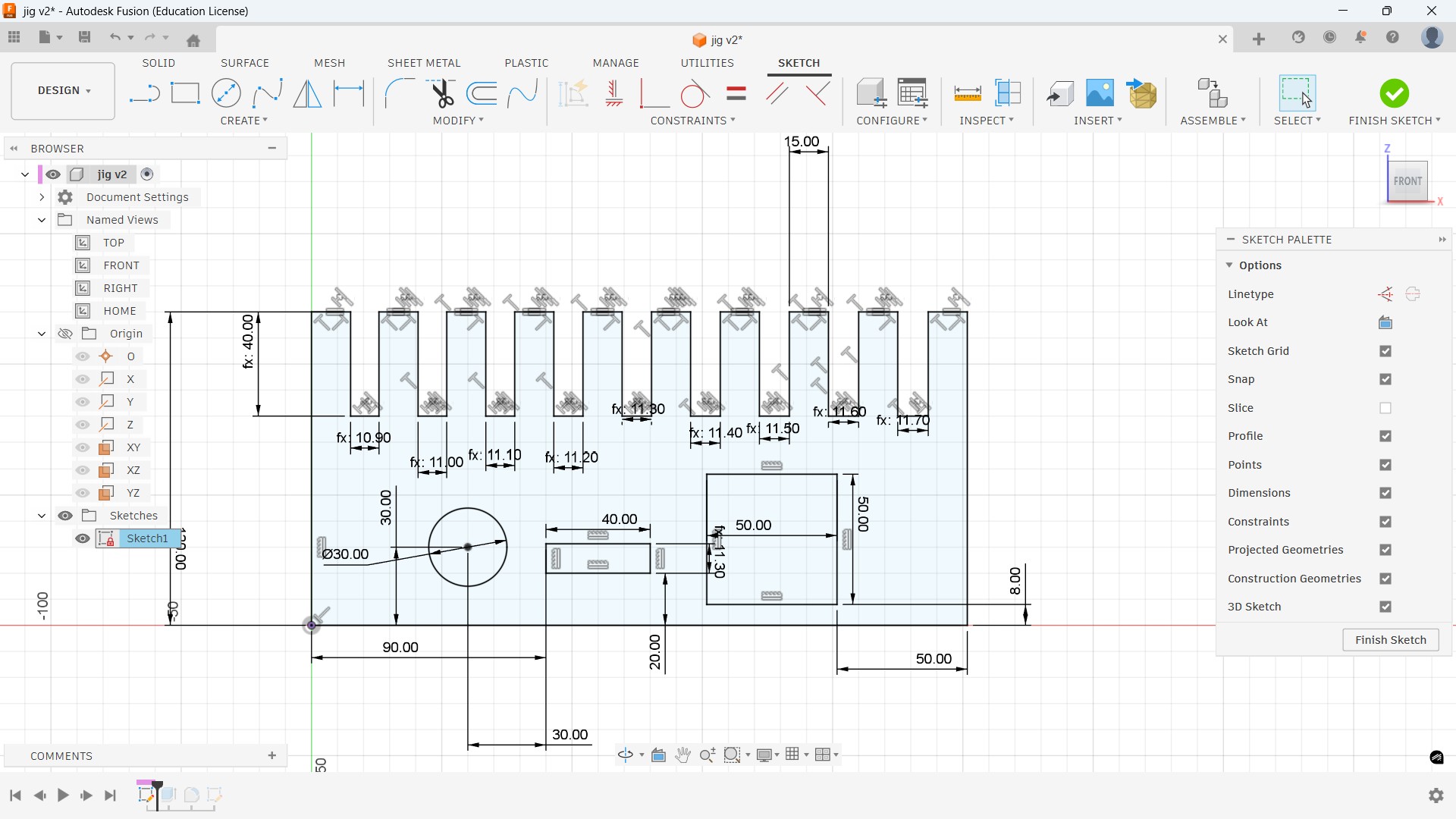
Based on this measurement, we created multiple slots by increasing and decreasing the size by 0.1 mm to find the perfect press-fit tolerance.
A test square piece was also included in the design. This square piece can be cut and inserted into the slots to check and compare the press-fit tightness.
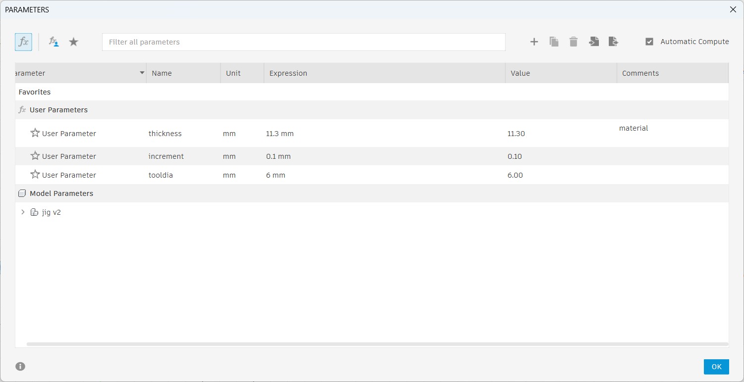
Parameters Used
- Material thickness: 11.3 mm
- Slot increment: 0.1 mm
- Tool diameter: 6 mm
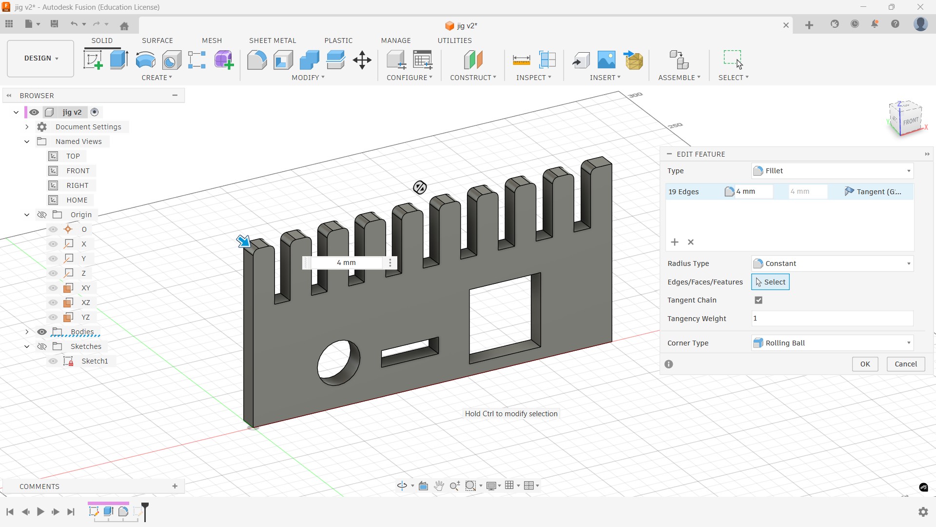
4 mm fillets were added to remove sharp corners and make edges smooth. This helps the test pieces slide into the slots more easily during press-fit, prevents corner damage, and allows smoother CNC machining.
VCarve Shopbot CAM Setup
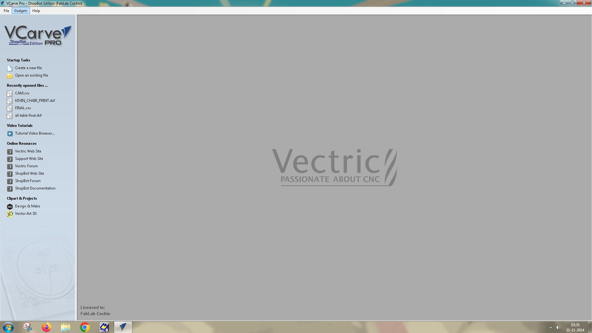
VCarve Pro ShopBot Edition is a specialized CAD/CAM software bundle included with new ShopBot CNC machines that helps you design and generate toolpaths.
Click ‘Create a new file’ to begin the setup.
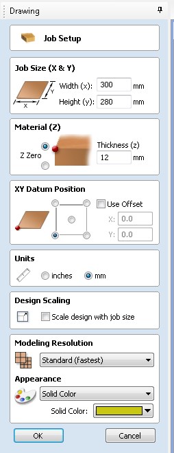
- On the left side of the window, under ‘Job Setup’, enter the material dimensions:
- Width: x
- Height: y
- Thickness: z
- Units: mm
- Click OK
Next, use the Circle tool under Create Vectors on the left-side toolbar to create marks for drilling screws later.
Set the circle diameter to 6 mm, since that matches the endmill size. This allows the workpiece to be secured to the sacrificial piece underneath it during machining.
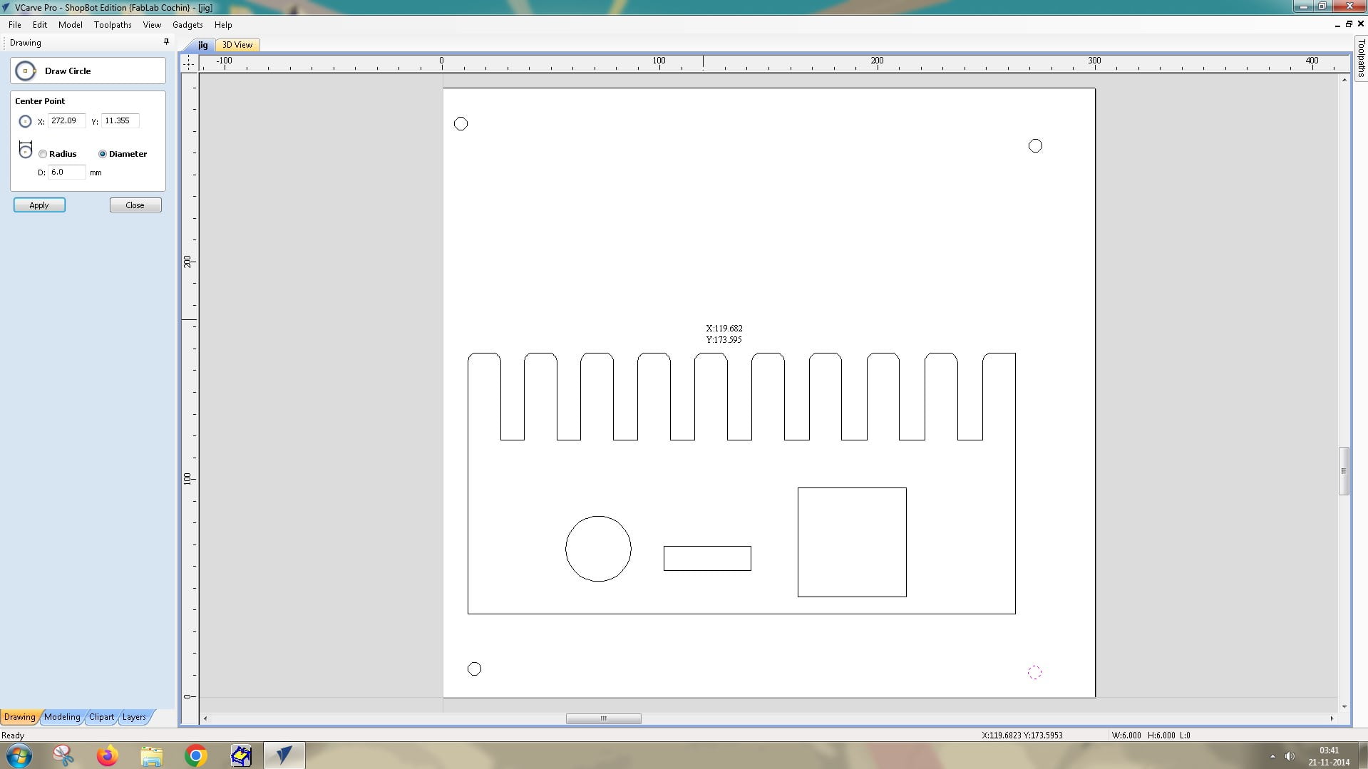
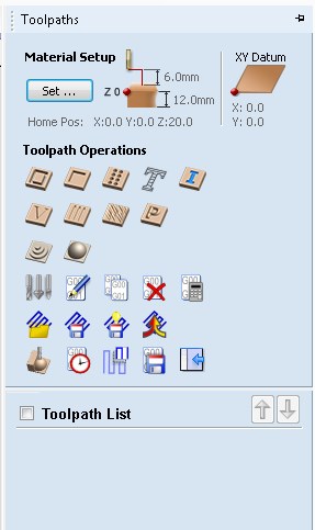
Once that’s done, click the ‘Toolpath’ tab in the top-right of the interface. This opens a new toolbar for material setup and additional edits.
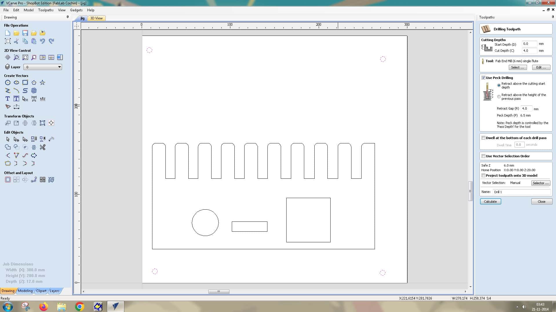
Select Drilling Operation (third on the first row under Toolpath Operations). A new window opens with options to edit Cutting Depths:
- Start Depth: 0.0 mm (where the operation begins)
- Cut Depth: 4.0 mm (we are not drilling all the way through, only marking holes to manually drill the screws later)
Tool: Fab End Mill (6 mm) Single Flute
Click ‘Calculate’.
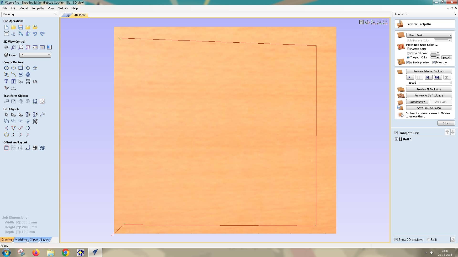
The toolpath is previewed in the ‘3D View’ tab next to it. This interface lets you preview multiple toolpaths and shows the toolpath list.
The next toolpath operation is a 2D Profile Toolpath. For this, we selected the inner elements in the drawing: the circle, rectangle, and square.
Start Depth: 0.0 mm
Cut Depth: 13.0 mm (set deeper than the material thickness to account for uneven thickness, with a sacrificial layer placed below)
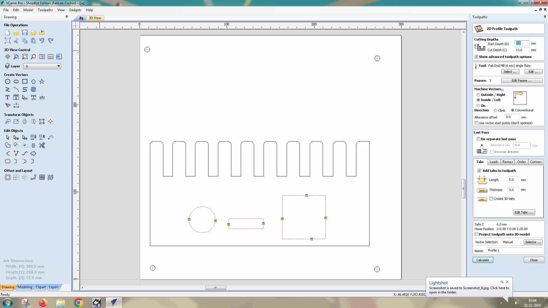
Tool: Fab End Mill (6 mm), single flute
Passes: 3
Machine vectors: Inside/left (because we are cutting the internal components from the main body)
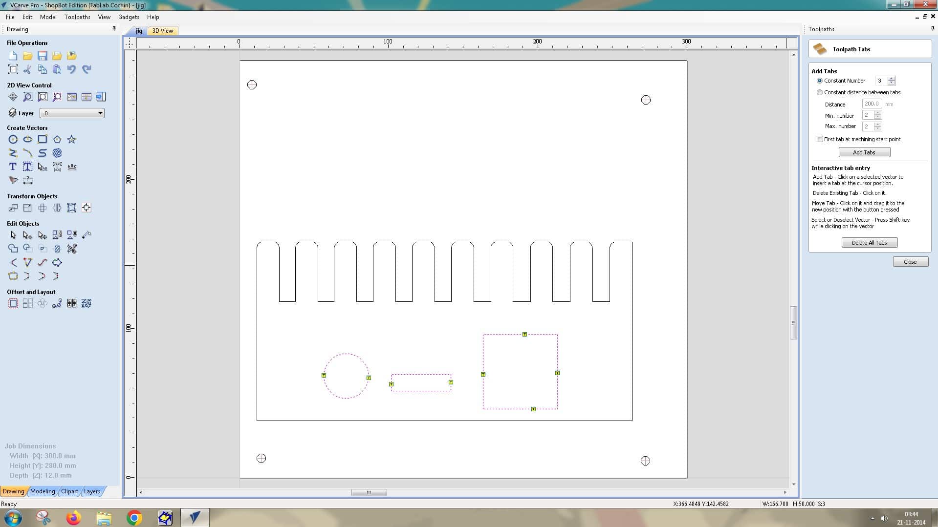
Next, we added tabs to secure the piece to the main body so that it remains attached during cutting and does not shift. This part can be chiselled off later. Then, we click Calculate to generate the toolpath.
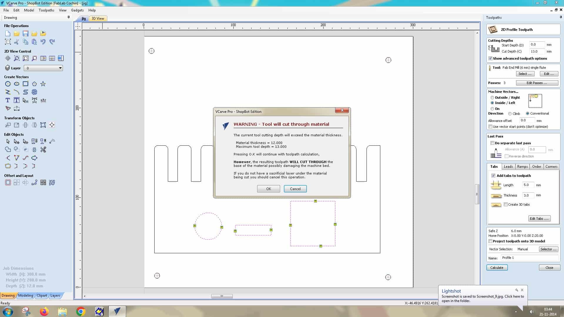
A warning window will pop up, saying the tool will cut through the material because we set the thickness to 12 mm and the maximum tool depth to 13 mm. We did this intentionally, so click OK.
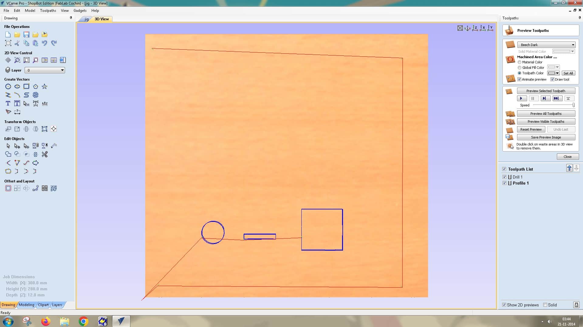
The 3D View lets you preview all toolpaths created so far.
Next, create another 2D Profile Toolpath for the jig outline.
Repeat the same steps, with one exception:
Machine Vectors: Select Outside/Right to cut the main component from outside the line.
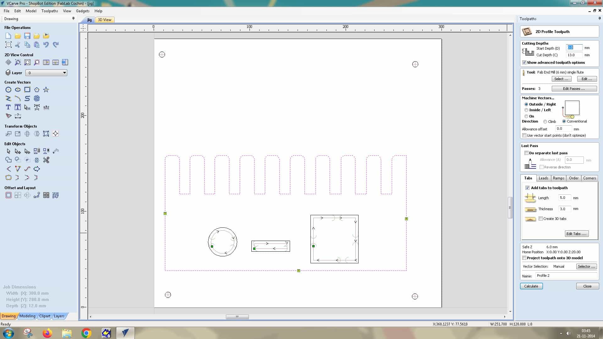
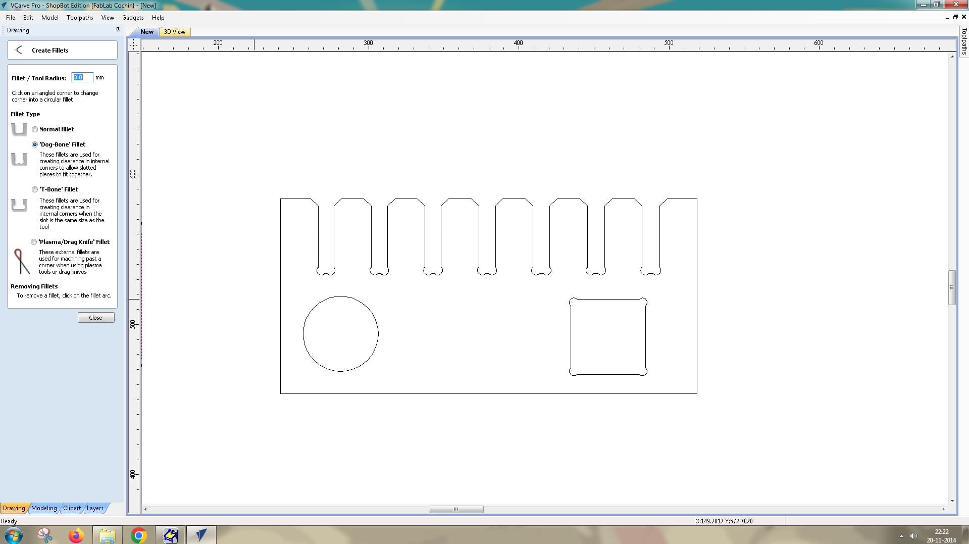
Now, go back to the jig drawing and add a dogbone fillet to the inside corners of the jig’s slots. Since the end mill has a 6 mm diameter, it cannot cut perfectly square internal 90-degree corners, which would make test-fitting difficult later.
To do this, use the fillet options on the left-side toolbar and add a dogbone fillet to each inner slot.
Now add tabs to secure the component to the workpiece using the Tab Editor.
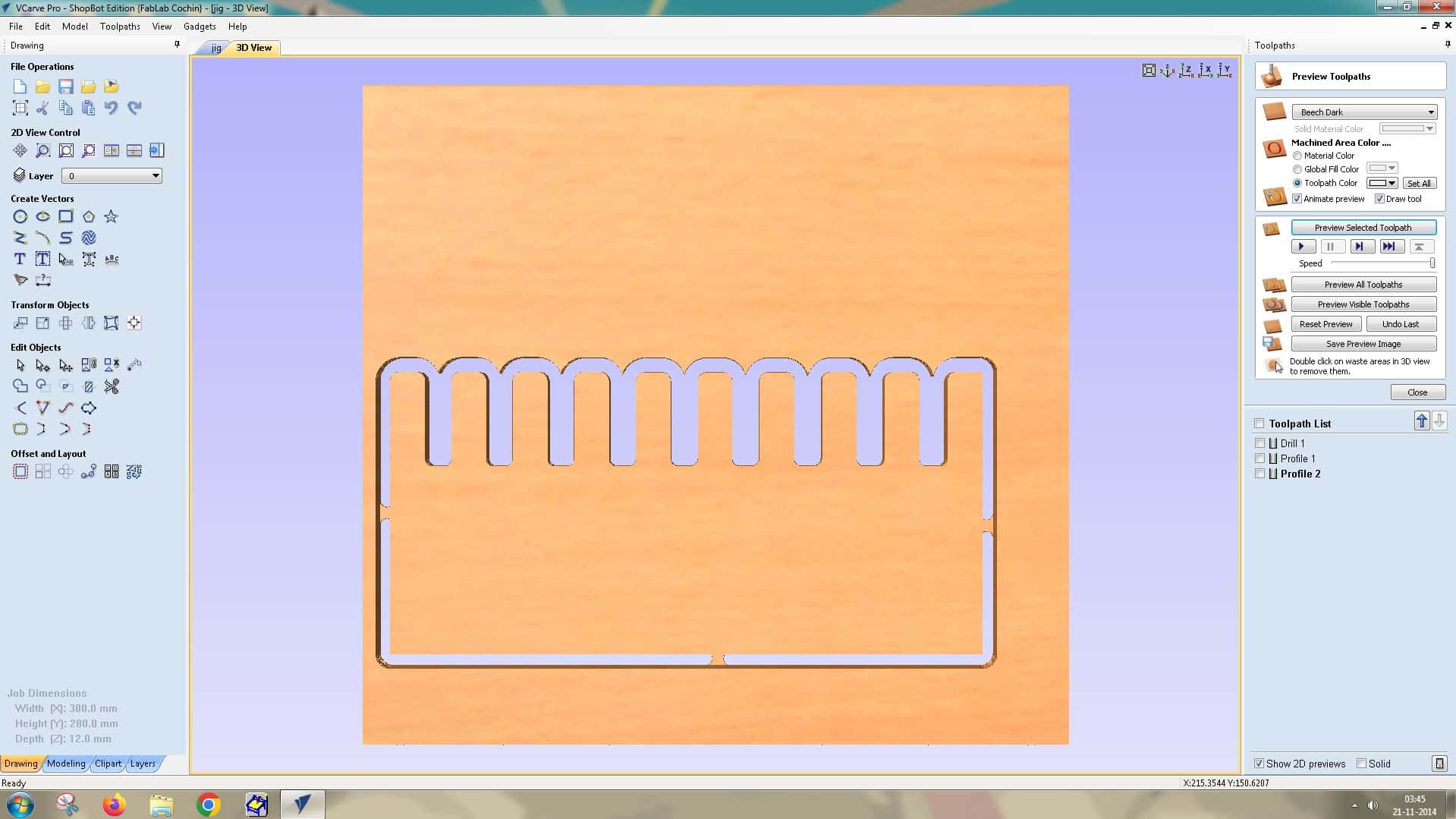
Preview available in 3D View
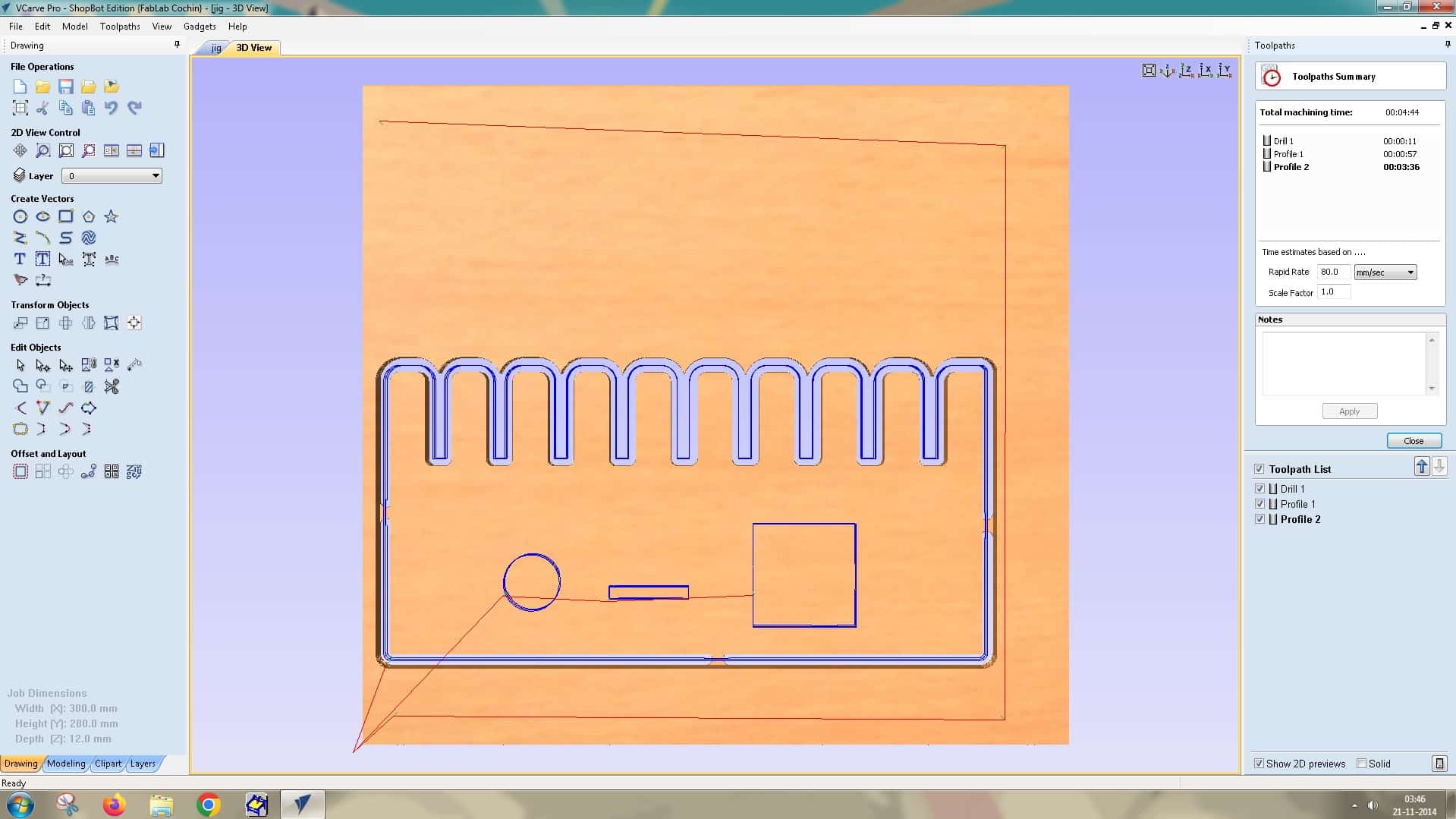
Use the Toolpath Summary option to view the total machining time (4 minutes 44 seconds). It also lists each operation and its estimated time, for example:
Drill 1: 11 seconds
Profile 1: 57 seconds
Profile 2: 3 minutes 36 seconds
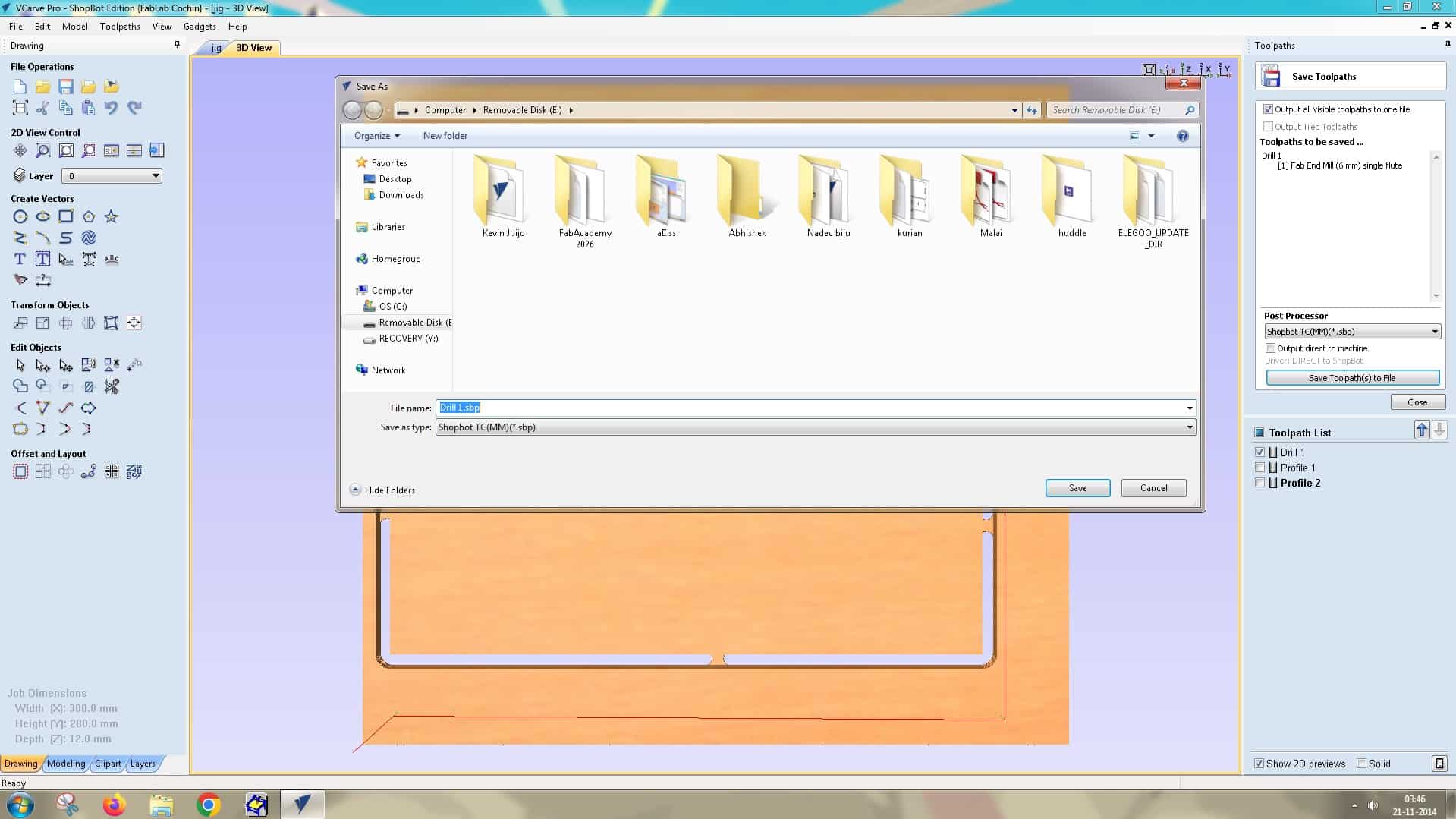
When saving, make sure the first operation, in this case Drill 1, is saved as a separate .sbp file, and save the next two operations as a single file. This ensures that, when running the profile cut operations later, we can avoid the screws and safeguard the bit from collisions and breakage.
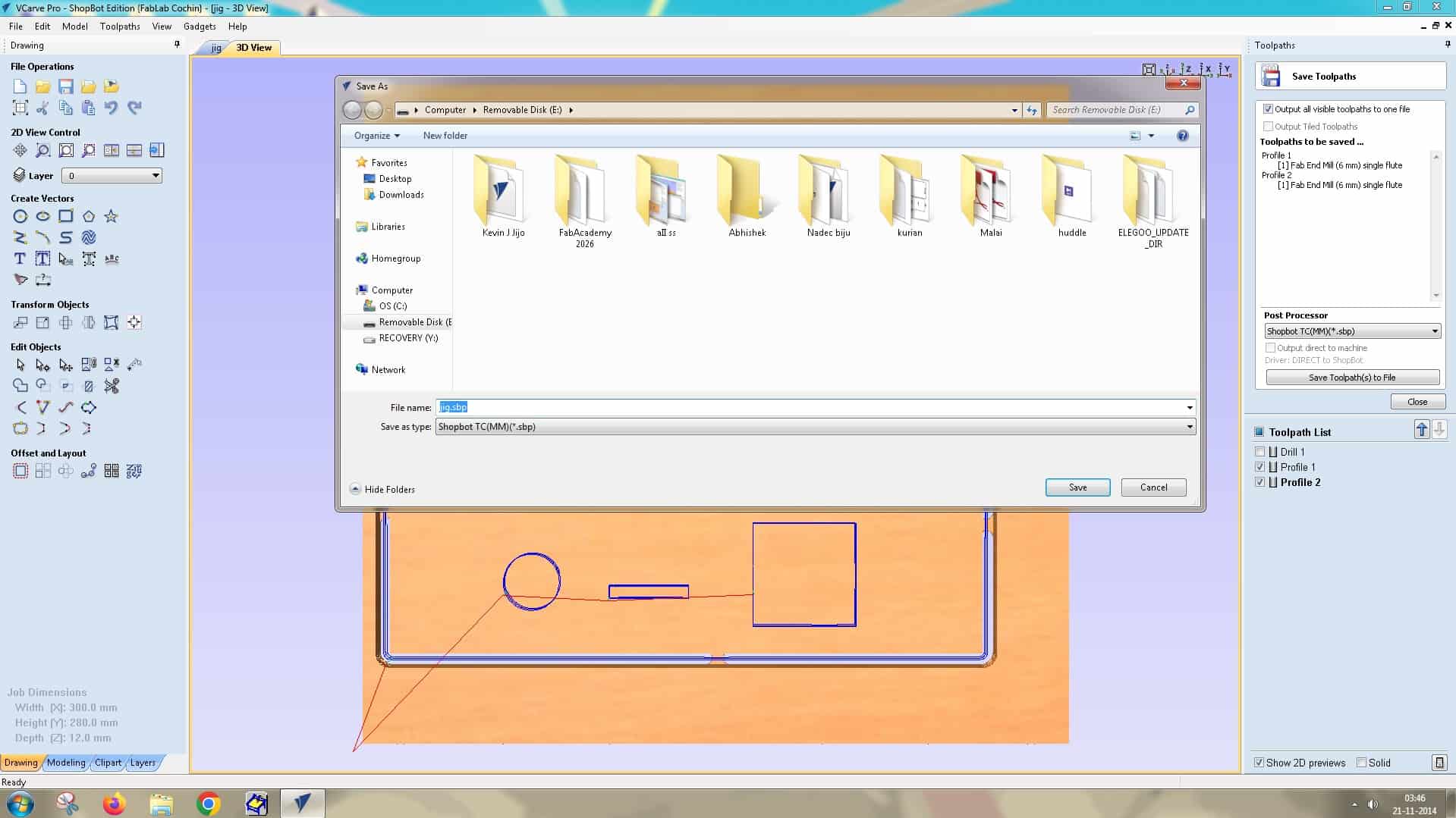
Save the VCarve file to conclude the CAM setup.
Operating the Machine:
Operating the ShopBot CNC machine involves a combination of software-based control and physical machine operations.
Two essential software programs are used in the workflow: ShopBot Control Software and VCarve Pro.
- ShopBot Control Software: This software directly controls the movement of the machine along the X, Y, and Z axes, allowing the operator to position the tool, set the origin, and execute the machining process.
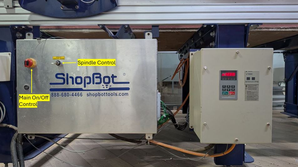
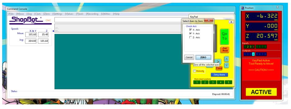
- Setting MCS X-Y Zero: Machine Coordinate System (X-Y Zero) this is done by clicking on x-y zero button on command console, the machine moves itself automatically and sets the x-y zero. it does it by detecting limit switch activation.
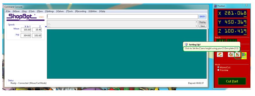
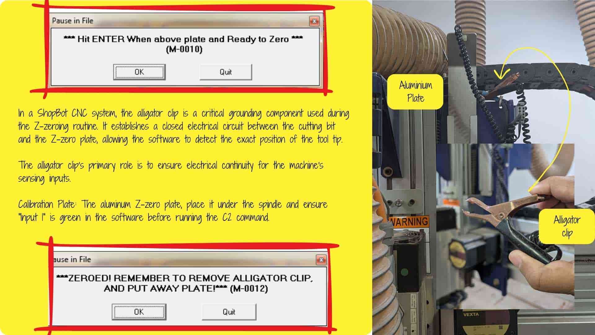
- Setting Z zero: In the ShopBot command control software, we clicked on set the Z zero height, using alligator pin and aluminum plate and it automatically reduces the thickness of aluminum plate from the Z zero settings.
Post- Processing
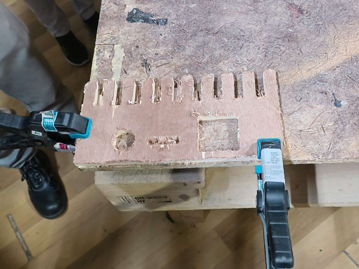
After the routing operation, we performed post-processing to clean up the workpiece, remove splinters, and smooth all rough edges. This step is essential to improve the final finish, ensure safe handling, and enhance the overall quality of the piece.
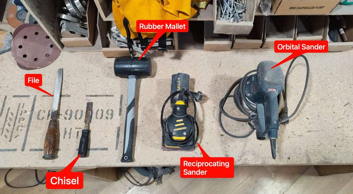
Tools used for post-processing:
- Chisel
- Mallet
- Reciprocating sander
- File
- Orbital sander
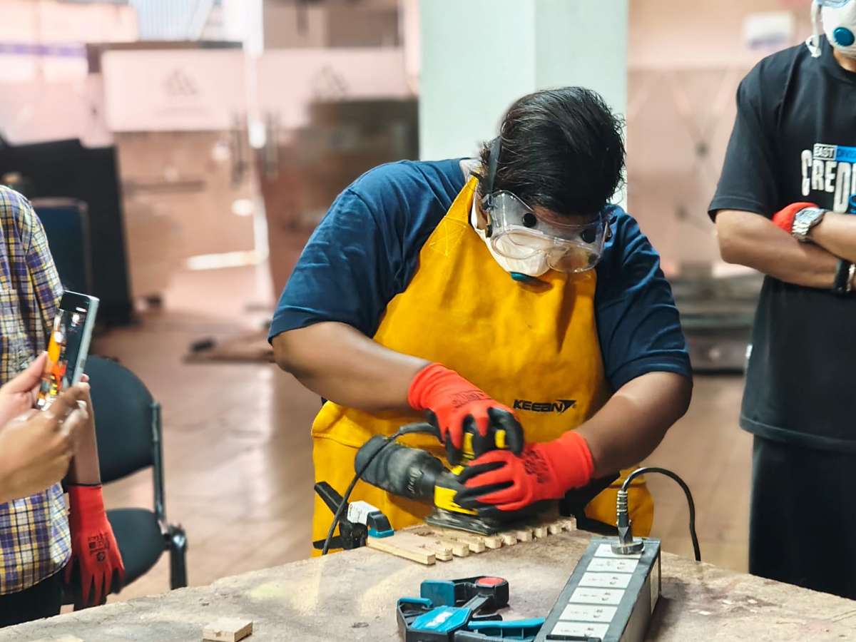
First we did some rough sanding with the reciprocating sander.
Areas that the sander could not reach were finished using a hand file.

The tabs were removed using a chisel and mallet.

For final finishing, we used an orbital sander to achieve a smoother surface.
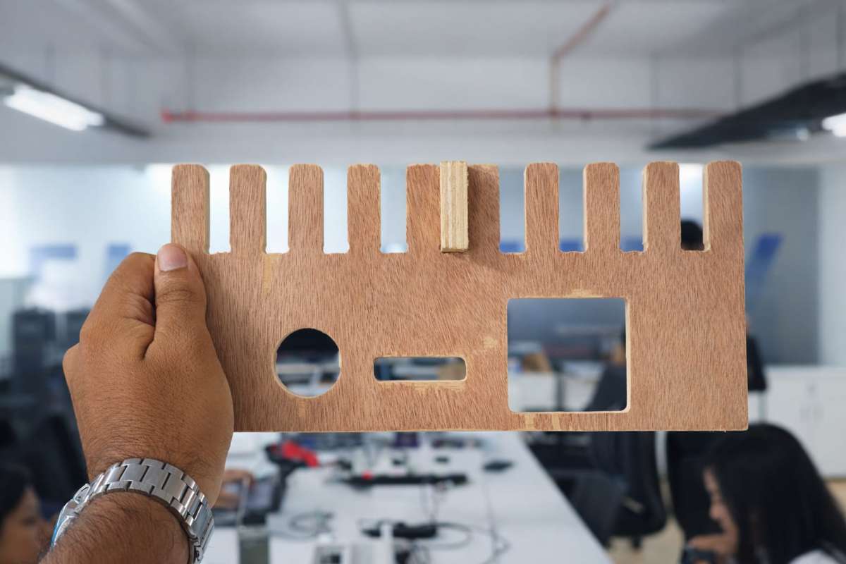
Finally, we post-processed the jig and determined the runout value to be Ply_thickness - 0.1mm.