Week 9
Assignment - Input Devices
-
Group assignment:
- Probe an input device(s)’s analog levels and digital signals (As a minimum, you should demonstrate the use of a multimeter and an oscilloscope.)
- Document your work on the group work page and reflect on your individual page what you learned
-
Individual assignment:
- Measure something: add a sensor to a microcontroller board that you have designed and read it.
From Assignment Details.
Group Assignment
Measure Something
Used:
- own-designed Input Board,
- oled screen (i2c),
- bme280 board from DFRobot (i2c),
- Multimeter and Osciliscope and Probes,
What to expect
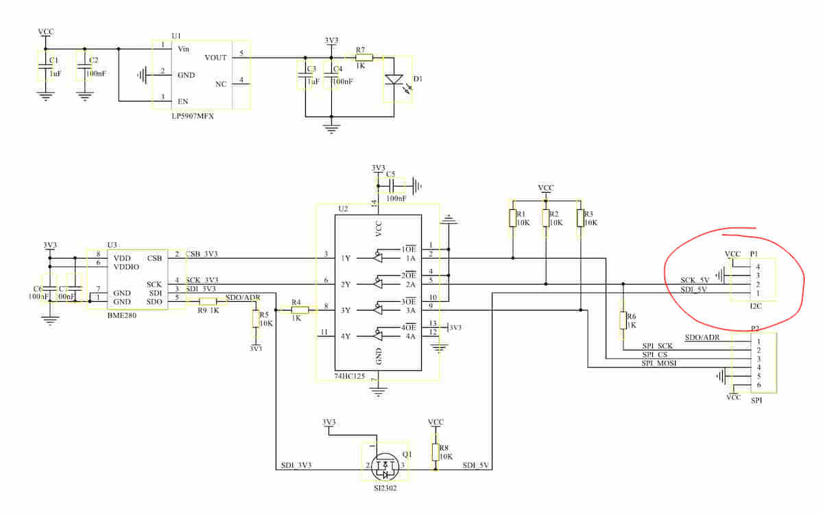
The BME280 is an environmental sensor (humidity, pressure, and temperature). The SEN0236 is an implementation of it by DFRobot with a I2C connector and pins for an SPI connection.
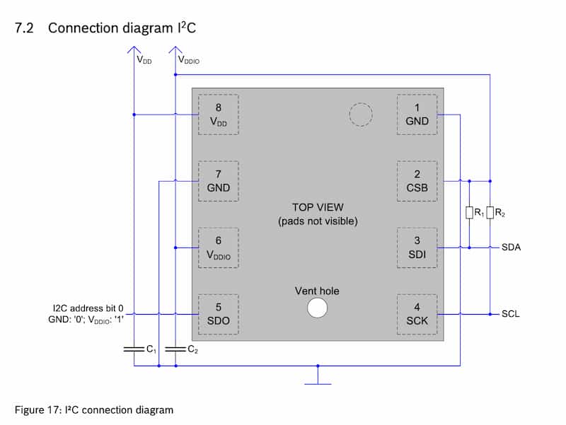
Because the component is surface mounted, it is kinda hard to probe, but based on the schematic of the SEN0236, the SCL and SDA connections are available at the “P1” connector.
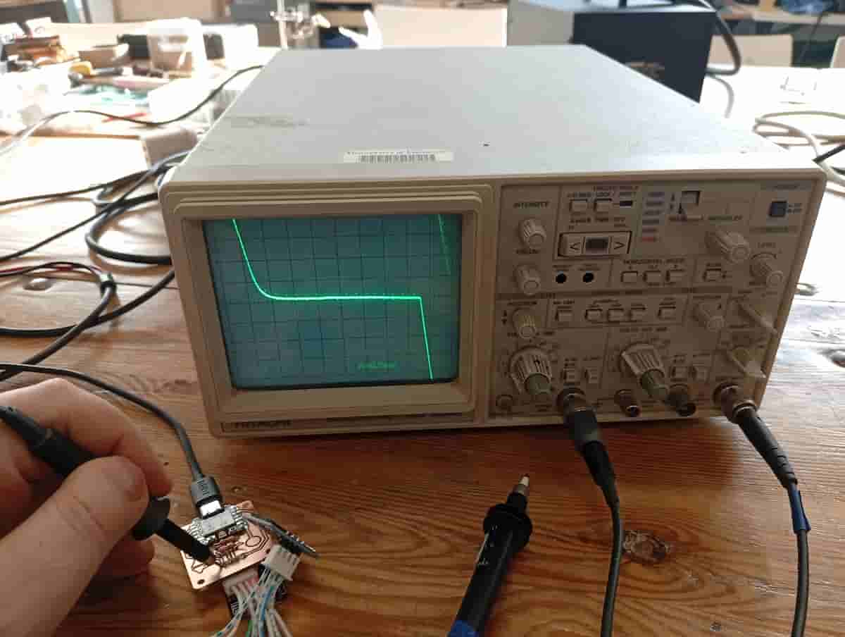
Connected:
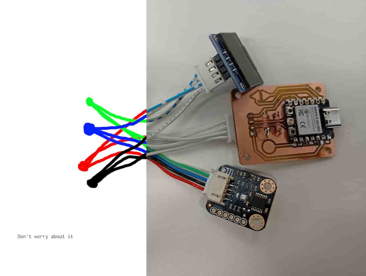
- temp image
- green is
SDA, and blue isSCL
Reflection
In this case, I was measuring to verify proper continuity and isolation, as designed. I measured the pins and board with a multimeter to test what logic level the board was operating at, and used the osciliscope to view the waveform of the CLK line of the i2c. I verified that each device was correctly connected to SDA and SCL, and that the board was sending the appropriate signals.
Working with I2C
I2C (I-two-C, or I-Squared-C) is a protocol for connecting a number of different devices to a microcontroller. Each device receives a clock line (SCL), and a data line (SDA), as well as VCC (5 volts) and GND (common). Using the clock line, a signal line can be split to many different devices according to their addresses. This is usually something like 0x00. With a device connected to a microcontroller, the microcontroller can scan the I2C bus and return the addresses. Sometimes a library written for a device, presumes the default address, set by the manufacturer, and so you can use these devices often without interacting with addresses, but I wanted to find them:
So, I wrote an I2C scanner example sketch (by Adafruit Industries, 2023 by Carter Nelson): writeup. The following is from the Serial Monitor:
Message (Enter to send message to 'XIAO_ESP32C3' on '/dev/cu.usbmodem145401')
New Line
115200 baud
15:54:09.755 -> Scanning...
15:54:09.755 -> I2C device found at address 0x3C  !
15:54:09.786 -> I2C device found at address 0x77  !
15:54:09.786 -> done
Knowing the I2C addresses(0x77 was the BME280, and 0x3C is the SSD1306 oled), I could upload a demo sketch to the board I made in week 8.
I used ChatGPT to try to make the demo code (log linked in the Files section).
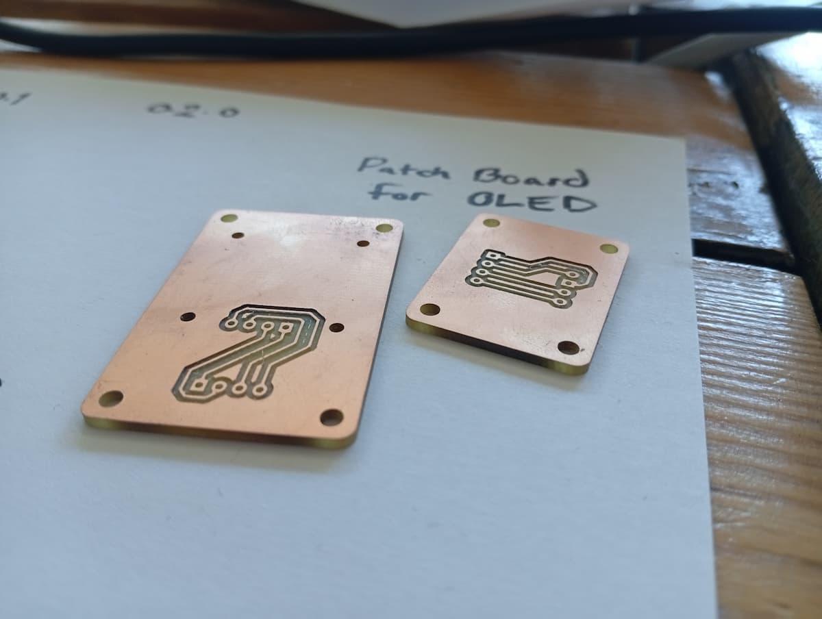
I designed the boards in week 8 to make it easy to connect i2c devices. Unfortunately, the order of the pins didn’t match either. For speed, I solved this with the cable. This patch board was a short term fix, but as they say, “There’s nothing more perminant than a short term fix”.