Week 2 - Computer-Aided Design
Assignment - Computer-Aided Design
- Model (raster, vector, 2D, 3D, render, animate, simulate, …) a possible final project, compress your images and videos, and post a description with your design files on your class page.
From Assignment Details.
Conclusions
This week, I used Rhino and OnShape, GIMP and Inkscape.
Which is a mixture of Raster and Vector, Parametric and Drafting type tools.
To compare, I made this graph:
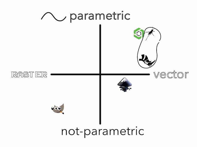
But this wasn’t the full story. Inkscape and GIMP are fully open, you can see all the source code, and edit it as you wish. People make many plugins that allow for e.g., GIMP to do batch processing, and Inkscape to do parametric path effects. Inkscape allows you to inspect the XML behind your drawings from the GUI, and both have command lines.
Grasshopper is a no-code/low-code plugin for Rhino, so even though it is proprietry software. It is extensible and parametric through this interface (I didn’t focus on Grasshopper this week).
OnShape has a variety of free and paid add-ons that bring a lot of additional functionality also.
These four are well-established tools, with their own specialities. Though general experience in a lot of tools is more useful. You can push these a little bit further, but it is useful to know when to try another tool!
Sections
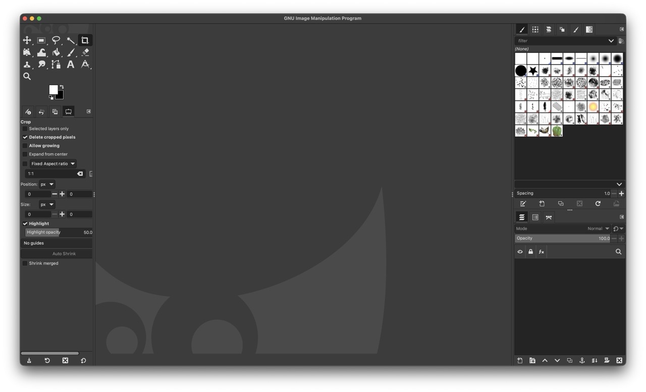
GIMP
GIMP is a free and open source Image Manipulation Program. I used it for compressing photos and images to use in documentation.
My typical workflow for making nice images from scanned drawings, is:
1. Rotate, Shift + R. (if necessary)
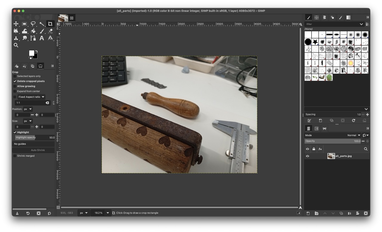
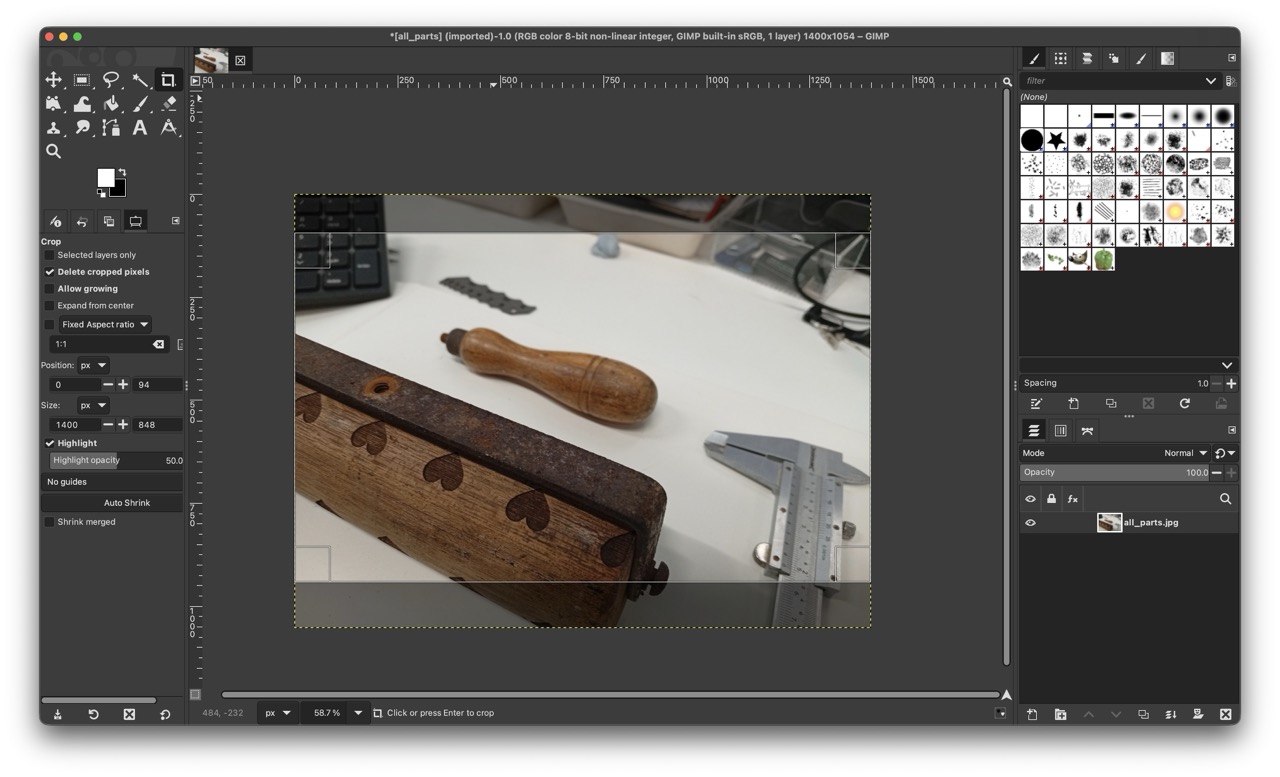
2. Crop, Shift + C, or  .
.
3. Desaturate (Color >Saturation... and make the scale 0).
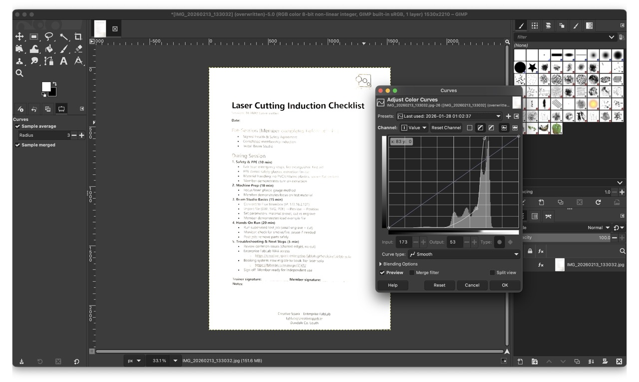
4. Curves (or Levels), is a graph of the values of pixels, and you can adjust brightness and contrast visually.
5. Color to Alpha... To make your white background transparent.
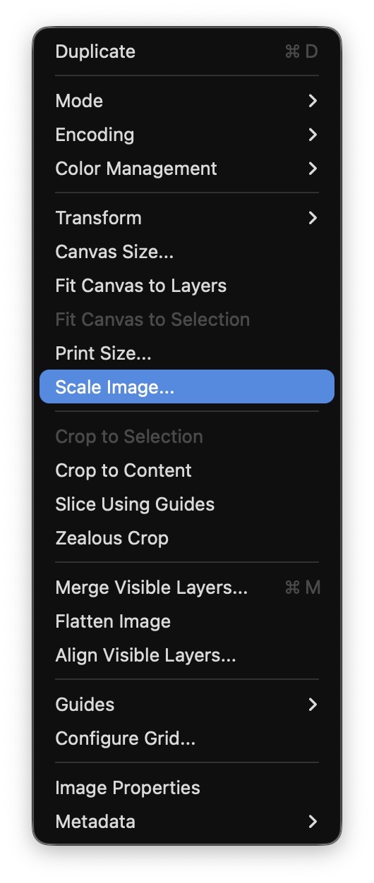
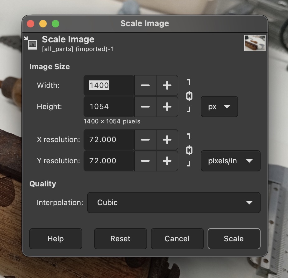
6. Scale Image... To set the pixel width, and proportionally resize everything. Choose the same as your imtended dimensions on your site!
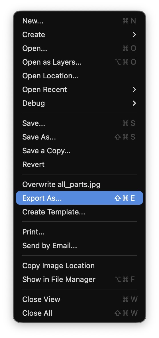
7. Export As... (automatically selected from the extension you type).
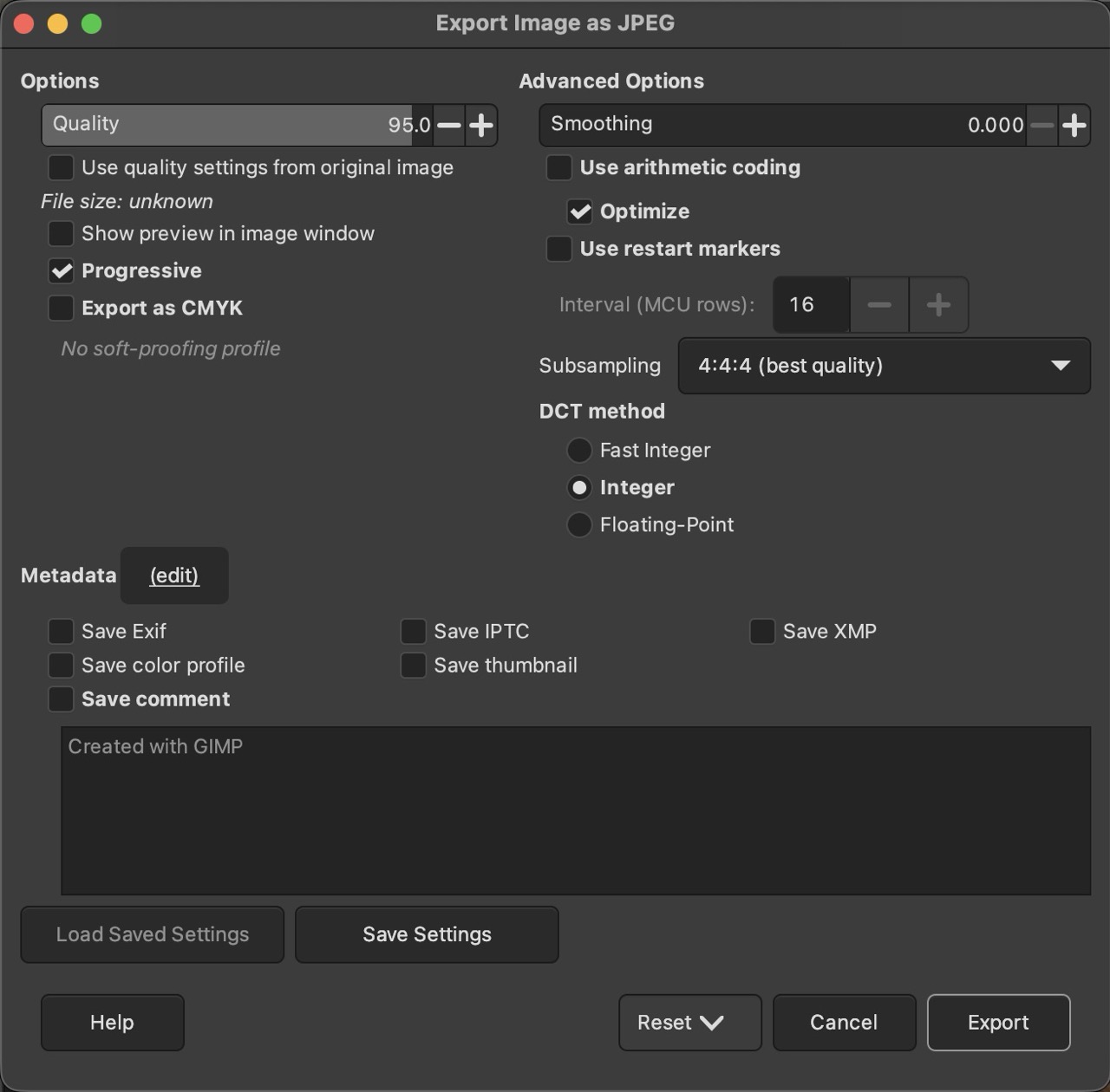
If you export a JPG or PNG, you can choose how much to compress as well as more advanced compression settings. Use the preview option to see the effect of your compression settings.
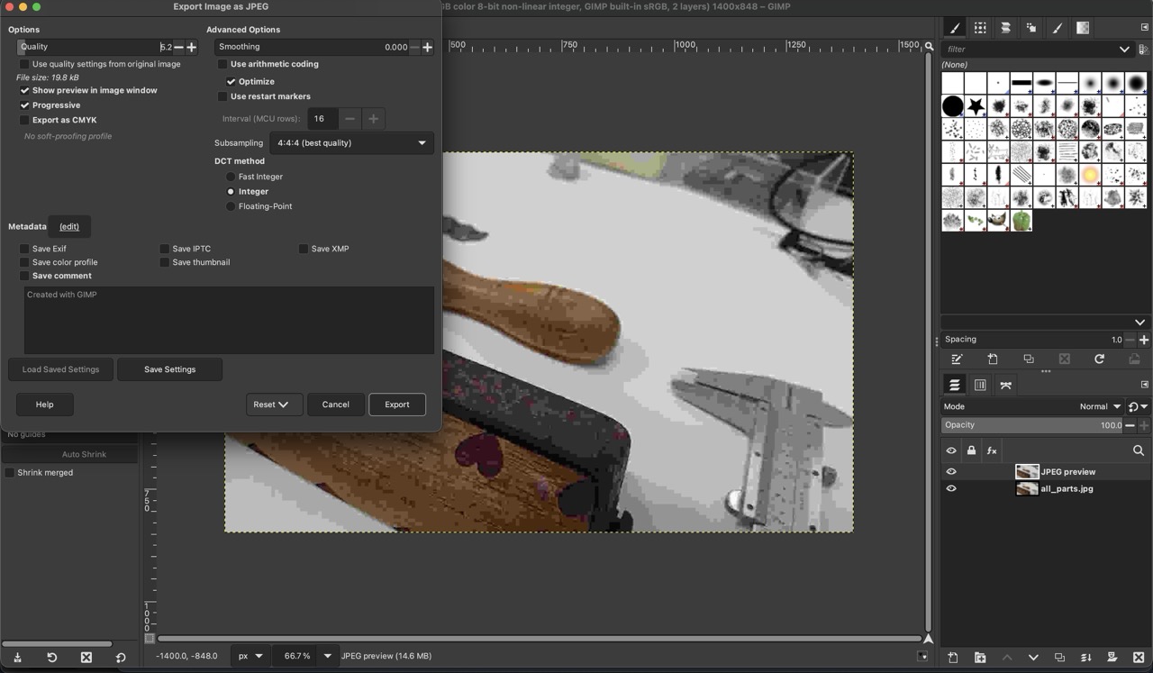
Closer up, with compression settings:
Comparisons with other options,
Squoosh.App is very visual, and you can see a preview of each image. The Batcher Plugin for GIMP, by Kamil Burda - works in GIMP, does a whole folder at a time. You can set up macros-style templates of your actions from inside the GIMP application. FFmpeg, is a command line tool, and is very powerful. It is the background to many other image and video tools, and as a result has more features. As it’s in the command line, it is easy and very powerful to automate your workflow.
Rhino
Rhino or Rhino 3D or Rhinocerous is a CAD program by McNeel. It is currently on version 8. It is available for Mac and Windows. It is popular in Architecture and 3D Jewellery design.
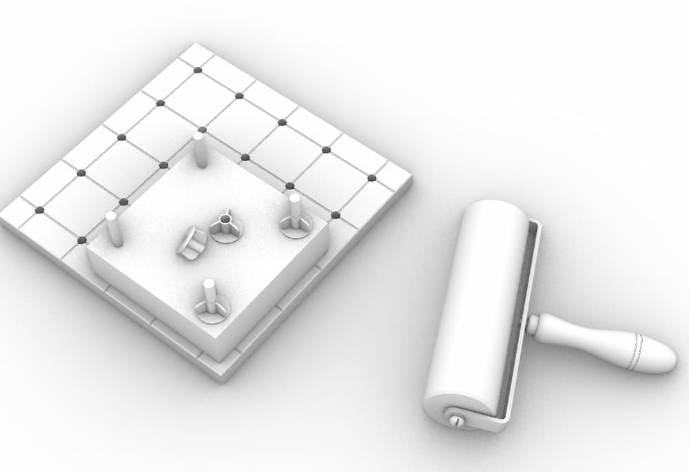
The first task I set myself was to draw up an existing part. It aligns to my final project, which is a glue roller. (This is an antique from the Print Making department in the Art College).
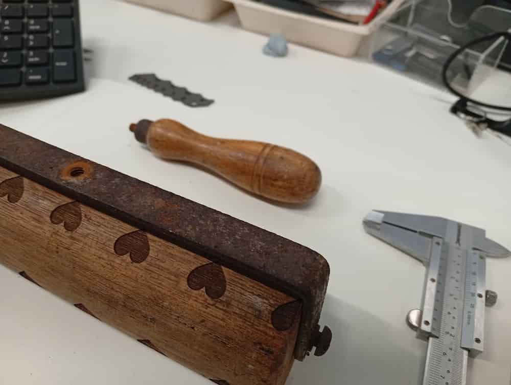
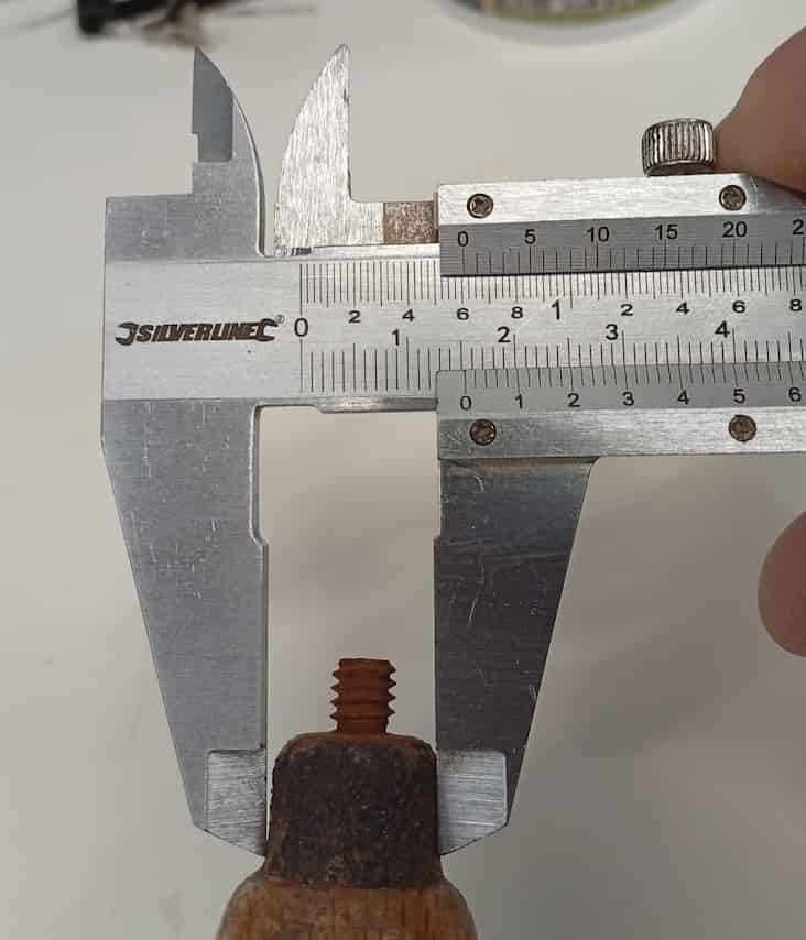
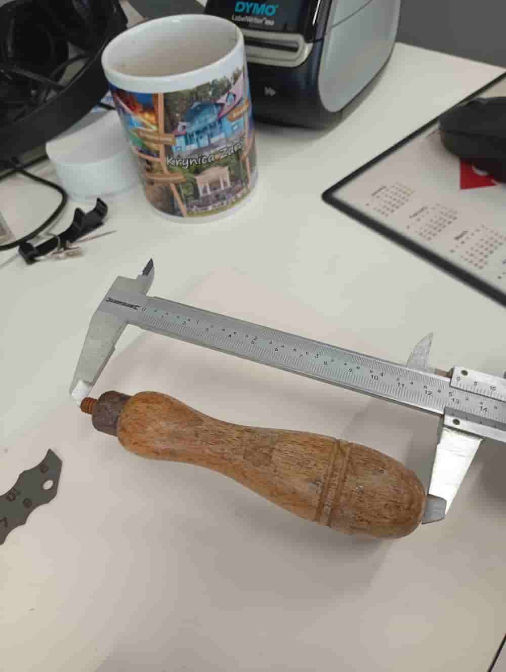
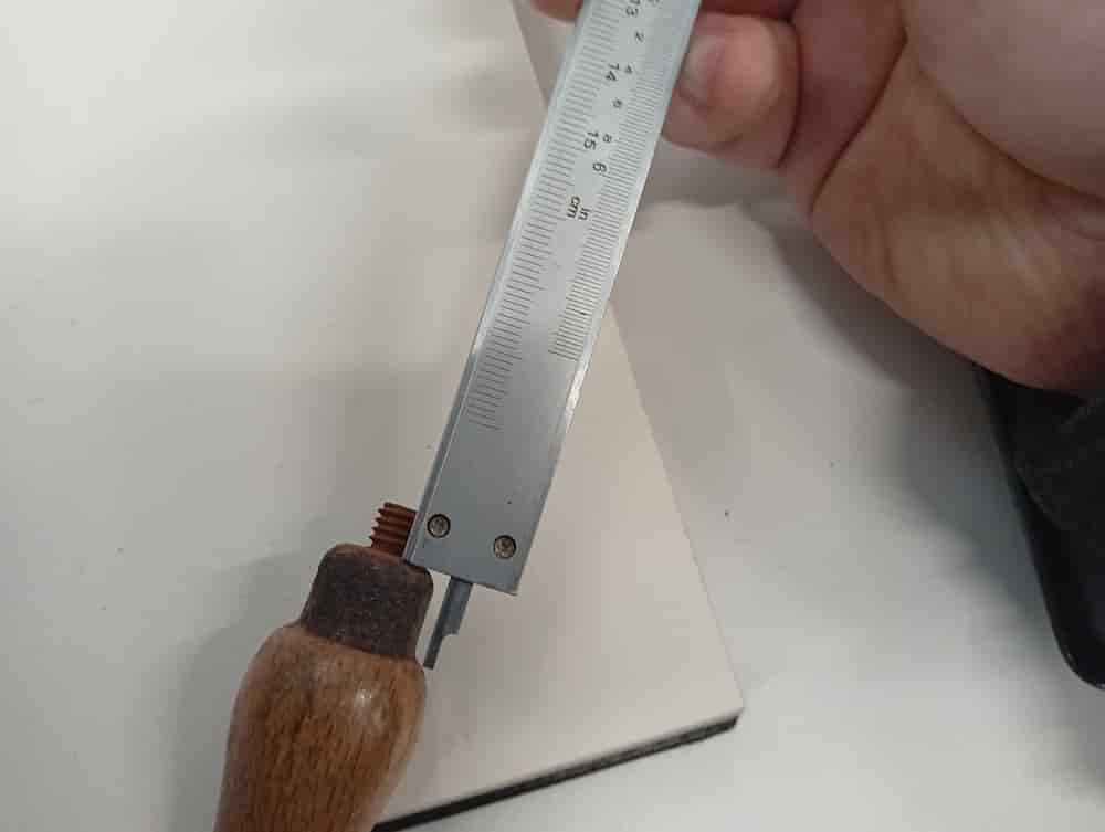
Learn to use a callipers and the Vernier Scale for extra accuracy.
Roller Pin
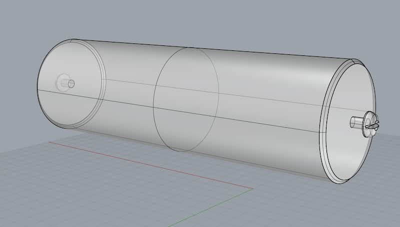
The screwhead is a cylindrical extrusion that is then heavily filleted to create the curve. Then the slot is subtracted.
The commands for this were:
_Circle. Type diameter of screwhead._Rotate, and then rotate on the Green axis, 90º. Or use the Gumball. Use_Moveif you need to move it to the centre again. The mouse snaps to centre points. Make sure you have snaps on andCentreenabled._ExtrudeCrv, and you can type the distance._Cap, or use theSolidoption to close the shape._FilletEdge, and type the radius. It will be less than or equal to the extrusion distance.
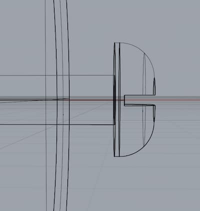
However, this slot is a little wider at the top. So I went back a step, and used Scale1D to make the shape a little more widge-like. Scale1D takes a startpoint, an endpoint and from that it takes the vector to apply a non-uniform scale, then you can type a number to scale to or click something to match.
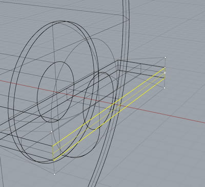
Then, Boolean_Difference, select screwhead, then Enter/Spacebar/Right-Click, and then the negative space of the slot, and then accept again.
Strap
The strap is a bent bar of metal with a threaded hole for the handle, and holes to hold the roller.
This has fillets on bends, and fillets laterally on the end corners. I used _Sweep1, with a Rail and a Cross-sectional profile. Then _Cap. Then _Fillet Edge. This was applied a number of times to get the final shape.
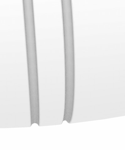
Handle
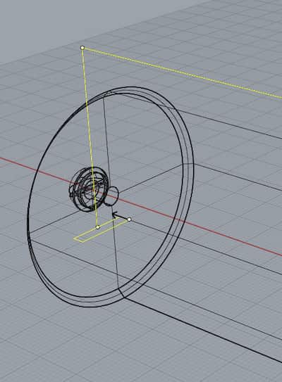
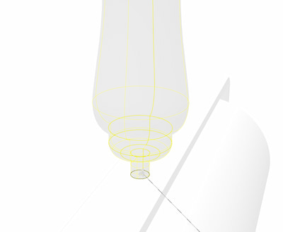
The Handle is axial, and based on the Rhino _Revolve command.
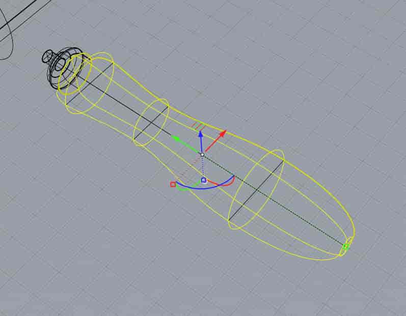
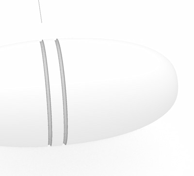
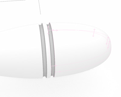
There were two features added by the lathe. This was created by subtracting two Toruses (_Circle, and _Pipe).
And, move to join the assembly. Follow Centre Snaps to make sure the parts line up.
Too big:
…Try again:
And with Fillet:
Assemble together:
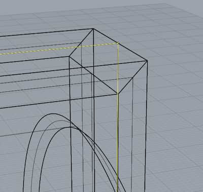
Wingnut Design
Vertical bars in this model are to be threaded (not done in this model). Wingnuts, threaded on the inside, tightens down the material stack.
This is a basic version of this part. Base and shaft to fit M8. Three wings at 120º to allow the nut be worked manually.
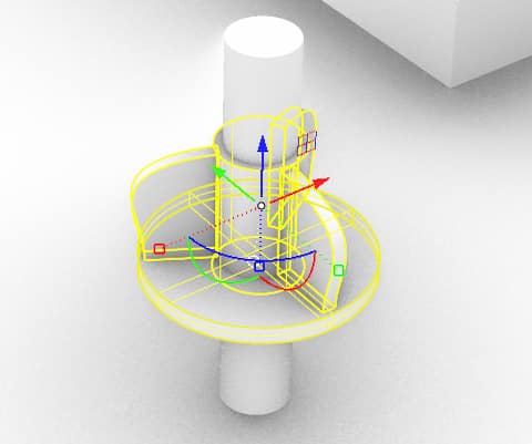
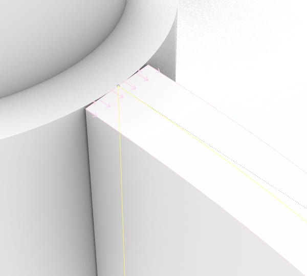
The wings are drawn as a cross-section joined with a handled curve, extruded to thickness, and copied and rotated around the central axis (I used the _ArrayPolar command in this case, but _Rotate with the Copy option could do the same).
To avoid these gaps, move the extrusion towards the centre before copying.
Use the Gumball Widget to move the extrusion, or adjust the points of the curve in plane. (The blue and green grid in this case).
Files
OnShape
OnShape is a parametric CAD program. It runs in your browser, has many modern tools for features like shared and collaborative working, parametric design and analysis. It is a paid program, with a free tier. On the free tier anyone can have up to 10 private projects, but for better features you should upgrade.
I did not have a specific outcome in mind for OnShape, just trying out a few things. I was interested to see how mated assemblies can map movving parts, and interested in using parametric variables, as a possible complement to a Rhino & Grasshopper workflow.
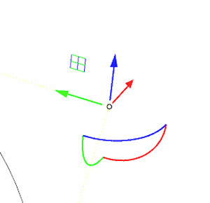
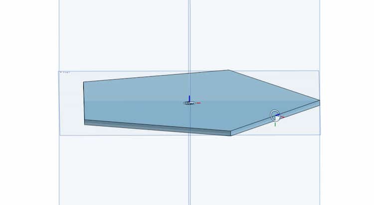
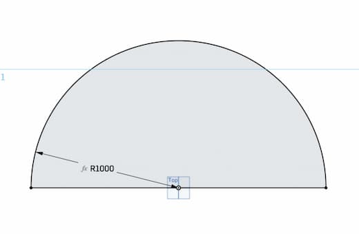
Parametric Dome
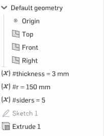

You can make Variables and use them (“after” == below in model tree structure). You can call variables instead of measurements and numbers (eg. of sides of a polygon). Type # followed by the variable name. As you type, it will prompt available variables.
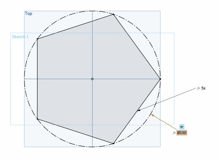
Using Variables in a Sketch
However, let’s declare these variables in the Variable Studio. Create it with the + icon beside your drawing tabs.
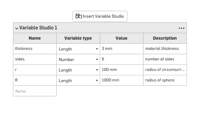
Variables on this table have document-wide scope. So, we can use the same variable in the sides of our part, as well as the pattern in our assembly.
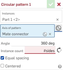
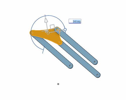
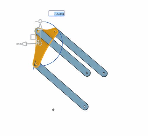
Hinge Constraint With Limits
Note: sides variable not updated!
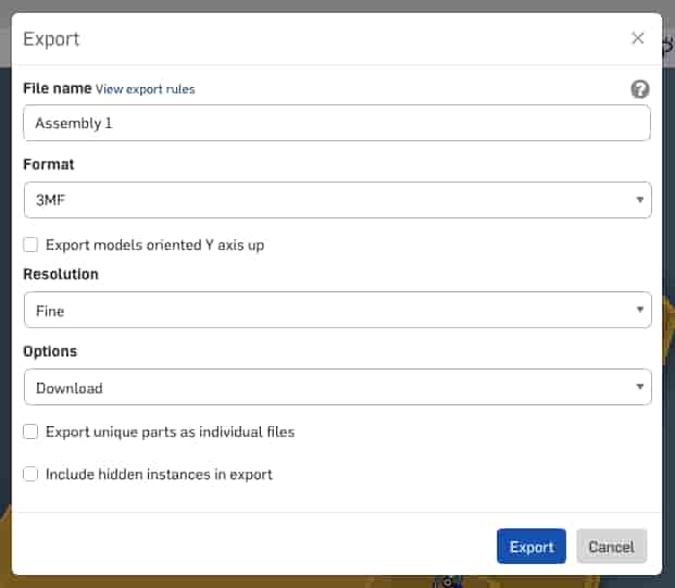
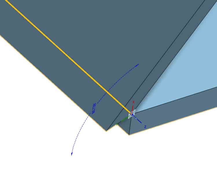
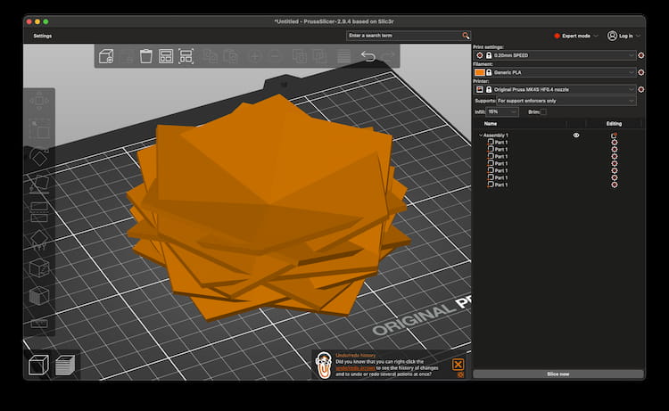
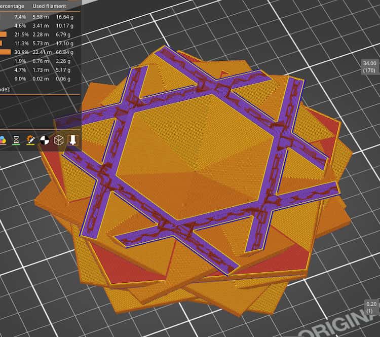
These were not the original intention, but we can still export a .3MF and get it to slice in PrusaSlicer!
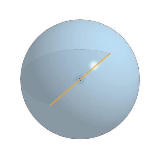
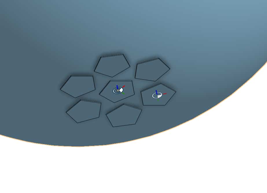
Next Approach
Maybe it’s better to make a construction sphere and then project a circular pattern on its surface. Or use a Flow Along a Surface command…
Import DXF
Used the MeArm project (V3.0).
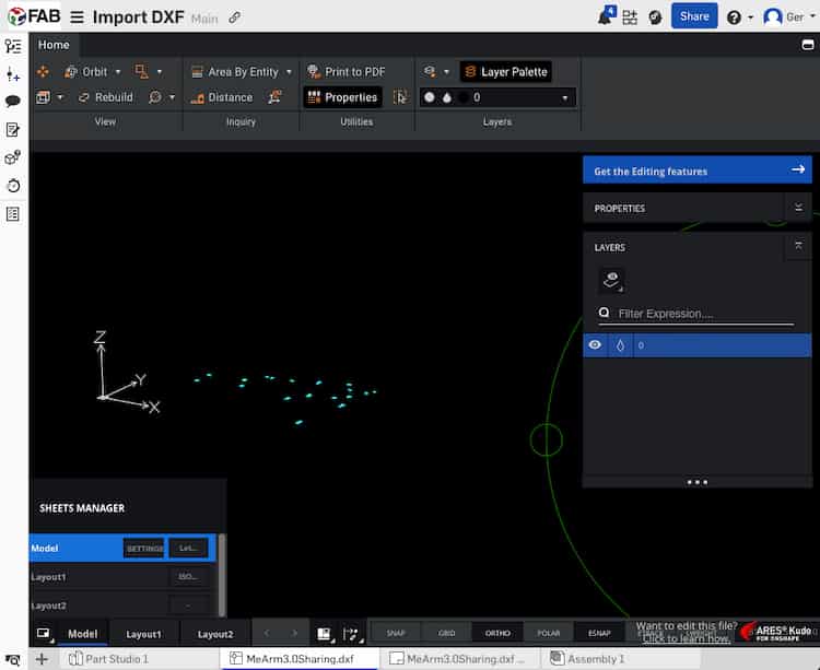
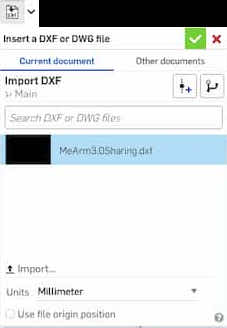
Started by using the
+icon to import the .DXF file from the computer. Found the DXF viewer unusable. Ignored.
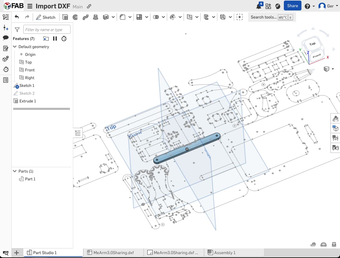
Started a new sketch, and used the icon above the screen to import a DXF straight into the open sketch.
Some features (tabs for the laser cutter) break the DXF lines, and I ended up redrawing those lines. Overlapping edges, better for material use, make it more difficult to isolate individual parts. So, I end up duplicating a new sketch, and creating a new body for each part. This can be done in the same parts work bench, as long as you’re careful to make new bodies each time.
A new nomenclature is required. I chose "Strut_Straight80082", for the 80mm x 8.2mm plain straight strut.
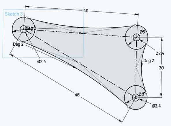
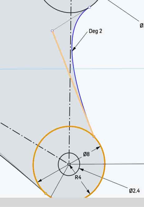
The elbow connector required more than just tracing. I drew the basic centre-line construction, used circles, and experimented with this metaball-like technique with bezier curves (used a tangent constraint at the tangent, and only a single handle point, to ensure perfect smoothness. I constrained the handle to the midpoint of the construction line, but this was just laziness. You could, if you wanted, build another construction line perpendicular, and use it to define a weight for the bezier.)


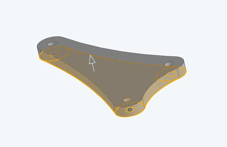
Mating The Components to Make the full Assembly
Files
Inkscape
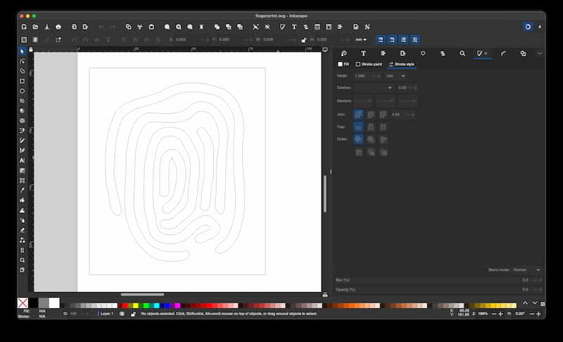
Inkscape is a graphical vector editor, it is free and open source.
Tools are on the left, file-related icons on the top row, Snap settings minimised on the right, and a swatch of colours along the bottom (right-click for stroke/fill options), and a little widget that allows you to set Colour, Line Weight and Opacity on the bottom left.
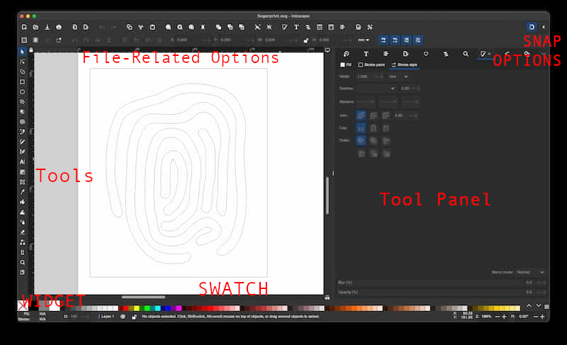
The interface has dockable panels on the right, that allow you to configure tools and make it easy to change tool and drawing settings while you work.
- Layers (at the top of the Layers menu)
- Fill and Stroke (Object menu)
- Align and Distribute (at the end of the Object menu)
- Transform (Object menu)
- Arrange (Object menu)
- Text and Font (Text menu)
1: Shape Builder
Shortcut: X, or 
- Select a number of closed, overlapping paths. Pay attention to the tip bar at the bottom as to what geometry type you have selected.
- Click and Drag the mouse between overlapping areas to intersect and union them.
- Hold the
Shiftmodifier to make a negative region and delete it. - Press
Enterto apply orESCto go back.
2. Outline Stroke
Use Path > Stroke to Path to expand a line to a vector of its thickness. It applies dashes and line thicknesses. Use with the Shape Builder to manage your intersections, and get the desired effect.
Or the Caligraphy Pen tool, this allows you to create freehand outlined strokes. Use Path > Union if there are any creases in the corners.
This technique can make this sort of image:
Download: fingerprint.svg