Week 13
Assignment - Moulding and Casting
-
Group assignment:
- Review the safety data sheets for each of your molding and casting materials
- Make and compare test casts with each of them
- Compare printing vs milling molds
-
Individual assignment:
- Design a mold around the process you’ll be using, produce it with a smooth surface finish that does not show the production process toolpath, and use it to cast parts.
Group Assignment
Safety Data Sheets
- Jesmonite
- XTC-3D, Smooth-On
- SortaClear(TM) 40, Foodsafe Silicone
- PLA
- 3M Hot Glue (…but can’t find specific brand!!!)
- Plaster, British Gypsum Easifill 60
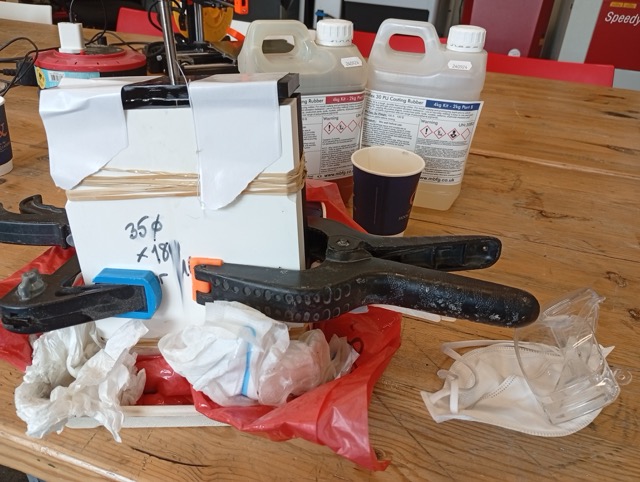
- Duroflex 30 PU Casting Rubber, Part A
- Duroflex 30 PU Casting Rubber, Part B
Test Casts
- Jesmonite
Steps
- Weigh out 56g of liquid and 144g of plaster (based on starter kit example mold provided), or use something like jesmonitecalculator.com.
- For AC1000, the ratio is 1:2.5 (powder:liquid), as follows:
| material | materialDensity | ratioOfPowder | ratioOfLiquid | Pigment |
|---|---|---|---|---|
| AC100 | 1.75 | 1 | 2.5 | 0.02 |
| AC730 | 1.95 | 1 | 5 | 0.02 |
Measuring the various sample moulds gives( with water technique):
| measured mold | mold nickname | material | density | total combined | how much liquid | how much jesmonite powder |
|---|---|---|---|---|---|---|
| (g, water) | density, g/cm^3 | g | ratio, 1:2.5 | ratio, 2.5:1 | ||
| 67 | flowerpot (each in set of 3) | AC100 | 1.75 | 117.25 | 33.5 | 83.75 |
| 108 | coaster | AC100 | 1.75 | 189 | 54 | 135 |
| 52 | 10x10 square 3D printed | AC100 | 1.75 | 91 | 26 | 65 |
I originally measured the 3D printed mold as 66g water (or 91g combined gpc). Though when I measured out the jesmonite liquid, I only had 26g left, so I adjusted the total amount and calculated only 52g water, which would fill the mold less.
I found a wider disposable container and mixed in that. I stirred with a wooden stirrer. But unfortunately the powder spilled, and the mix started drying immediately. I stirred until it was homogenous anyway, but it was too thick to pour,
- Hot Glue Injection
(See mold design below)
- XTC-3D (Paint-on Smoother PLA)
Individual Assignment - Mold Design
Designed an FDM printed mold.
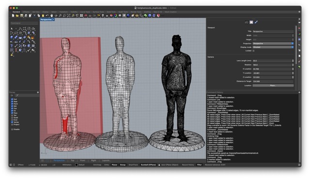
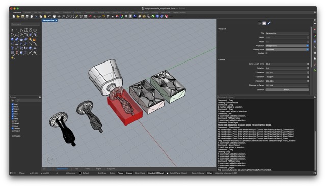
Tried some models from Printables.com
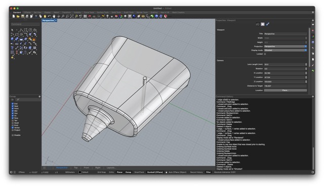
They were too intricate. So, I used ShrinkWrap in Rhino to reduce the mesh.
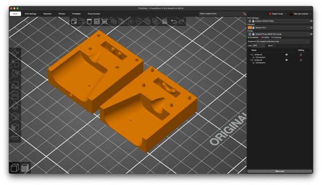
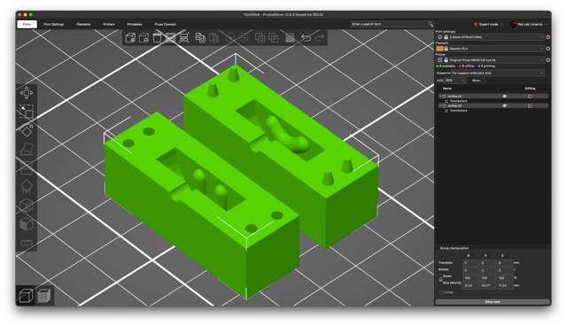
I measured a hot glue gun, and made a grasshopper script around automatically subtracting the mould adding sprues and splitting into two parts.
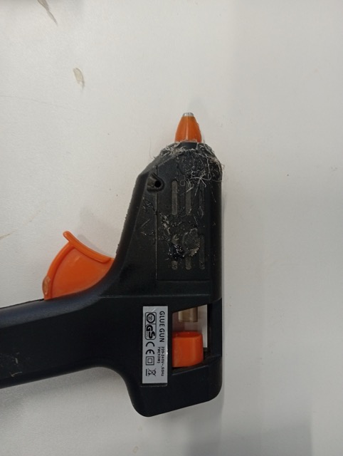
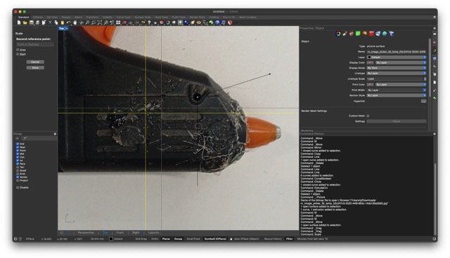
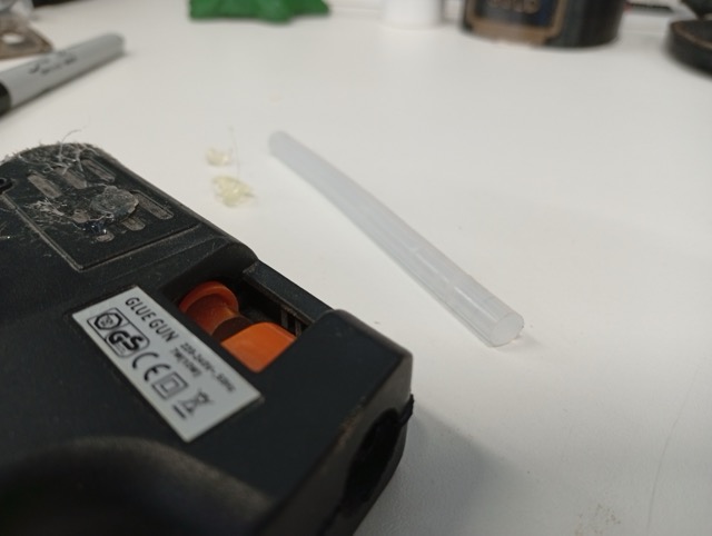
And I measured the material, a small gluestick refill, which was 7mm diameter and 98mm long.
Idea, instead of cutting in Grasshopper:
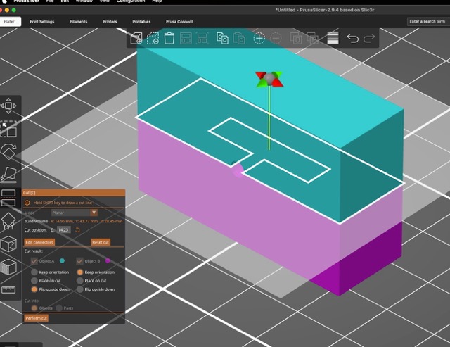
I used Prusa’s Connector Features to add alignment divets (this is part of the Cut tool). This actually gives you a neat way to add and position them when setting up the job and to test different tolerances.
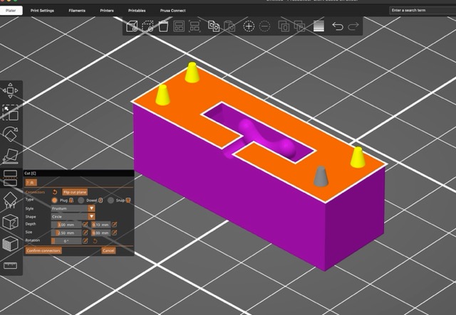
…Which gives:
And the intention is to make a more complicated pipeline that can take a variety of meshes.
But unfortunately at the moment, looks like this, because of mesh problems.
I found that if you made the mesh of two adjacent boxes in Rhino/Grasshopper, the mesh triangles already aligned with the cut tool and didn’t create any naked edges, so I added that to my script.
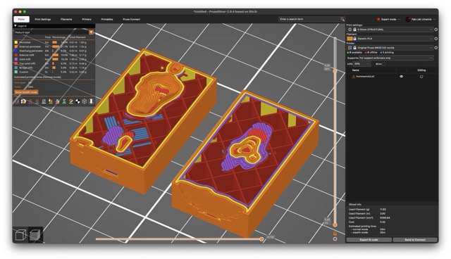
Version 2
In version 2, I made adjusted the nozzle tolerence, and made the injection point closer to the model. I made a panel in Grasshopper to show you what number to use in the “Cut” tool in PrusaSlicer. And copied the “pin” to another location, but I’m not sure if the adjustment is needed while also adjusting the overall tolerence.
I also made the settings for the alignment pins in PrusaSlicer shallower frustrum shapes with a 0.3mm tolerence setting. In this case, I had to cut at 15.013mm.
This mightn’t have been the correct move, it puts the injection point on the line of the seam.
Making the Rollers For my Final Project (3D Printed Molds)
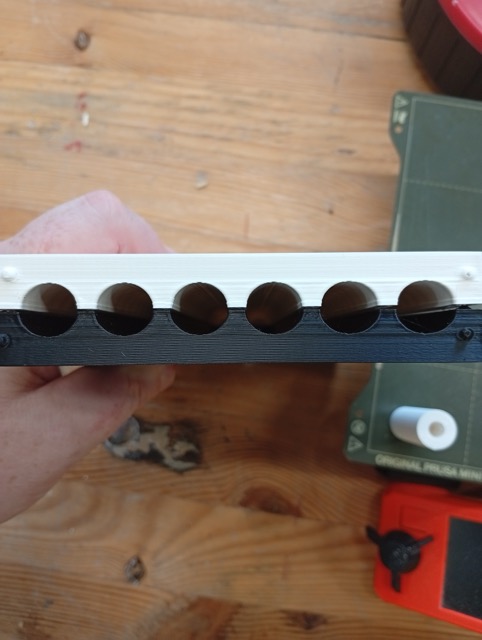
I did a 14mm version and a 35mm version. the centreholes that go through are for M6 rods, and the molds are in 3 parts (2-parts plus the lid). This is the 14mm version, printed:
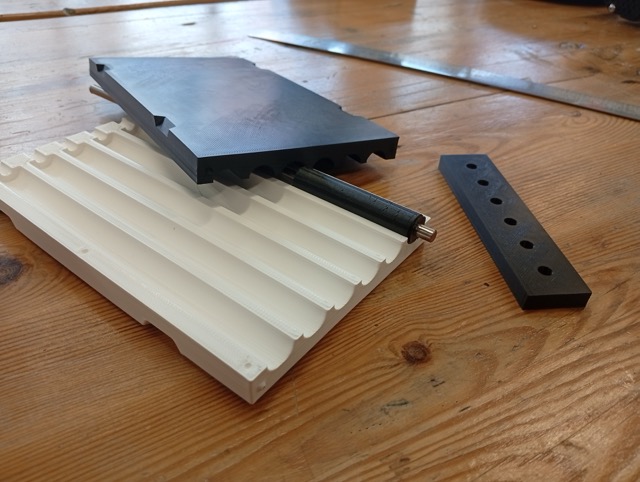
But are not round:
I sanded, and then applied the XTC-3D, Smooth-On material, as follows:
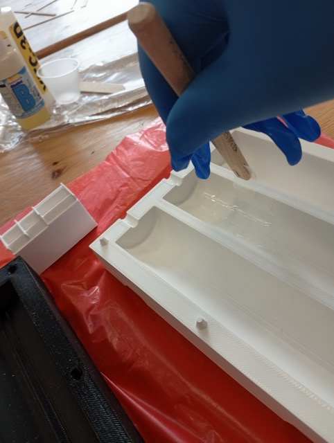
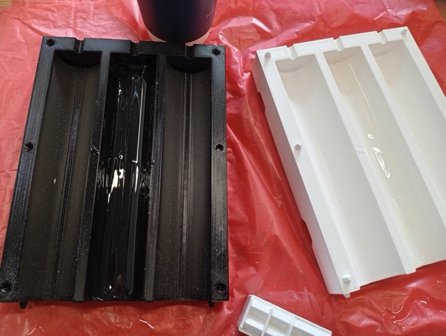
It was quite leaky:
??????Result image???
Conclusions
- Likely didn’t leave the XTC for long enough (pulled off).
- No release agent. Damaged on getting it out.
Files
????? Files 14mm and 35mm versions ??
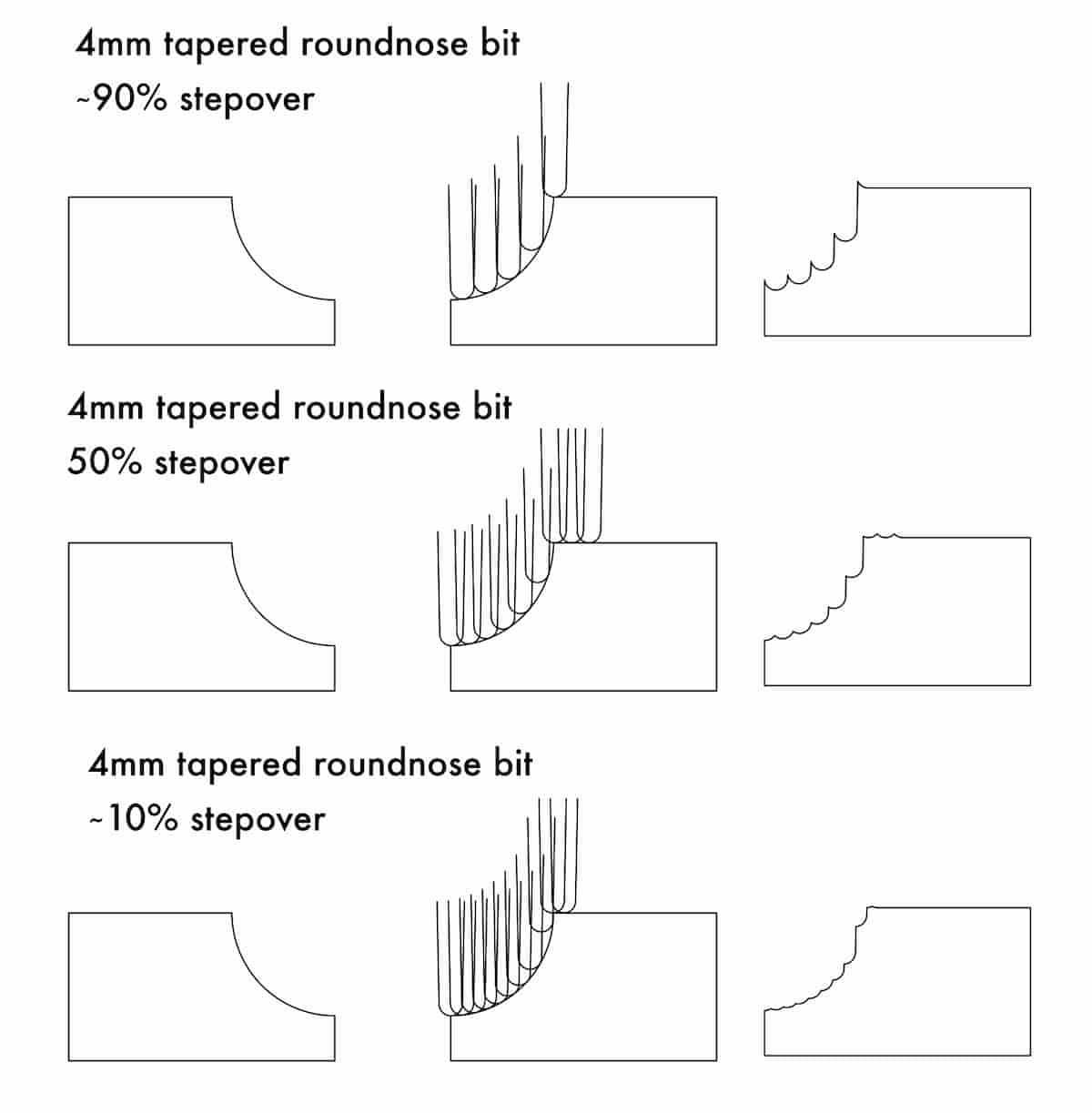
So, should I switch and make it in the CNC? (Ignore the Stepover numbers. I tried to calculate it, and set the dimensions in Inkscape, and I think the % looks pretty off, but it still has the general idea…)
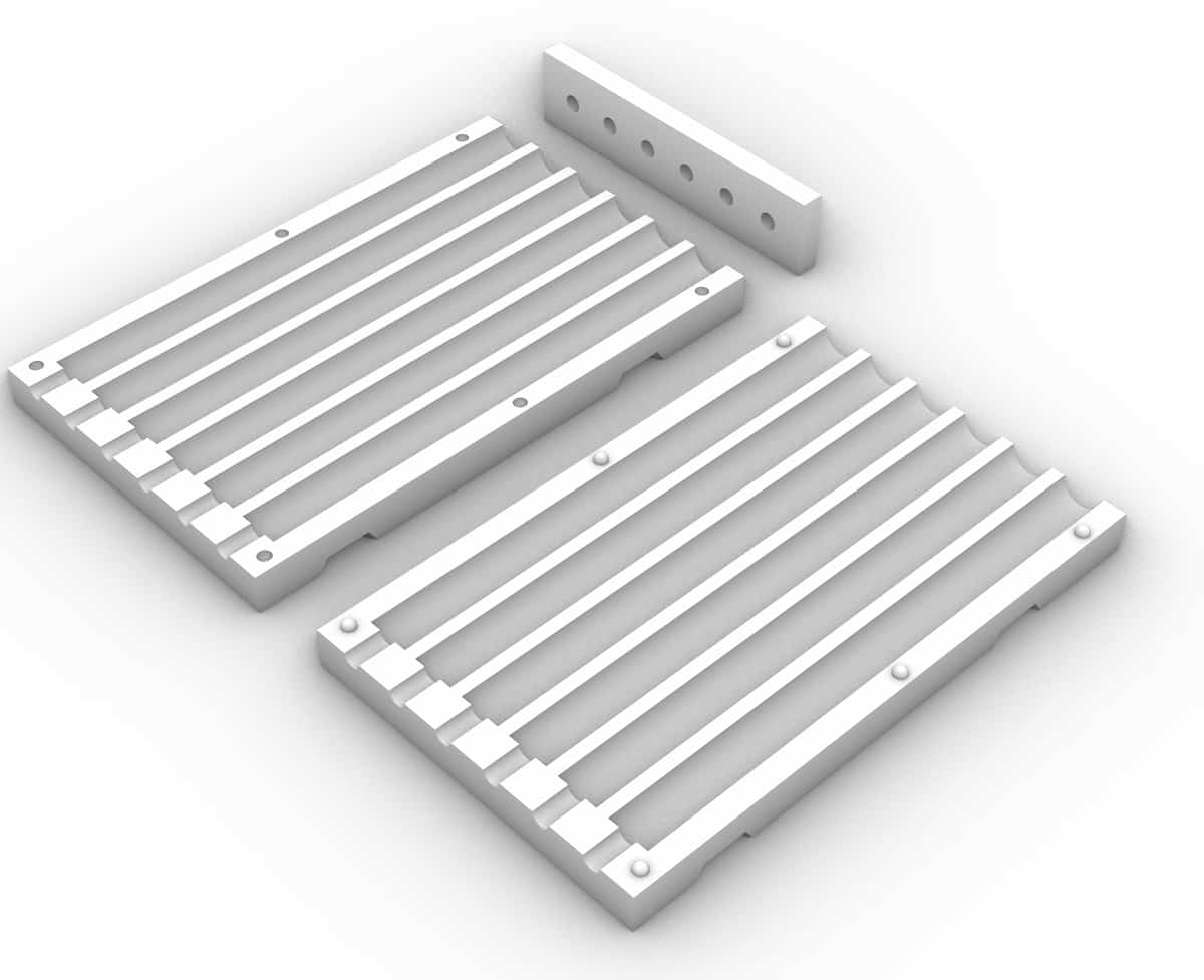
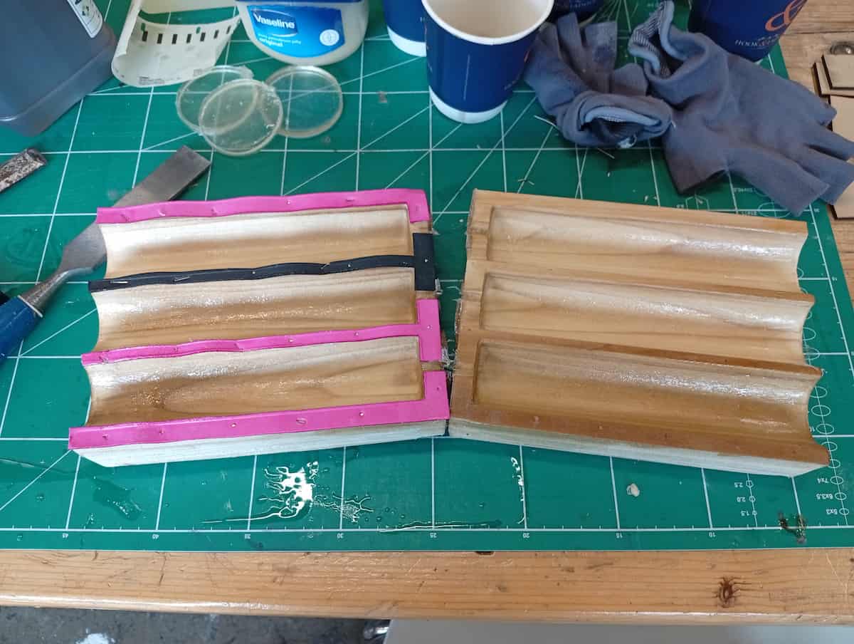
Wooden Mold (Attempt No. 3)
I redid the mold in timber to try again.
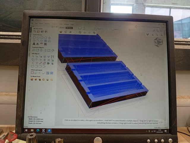
I milled it on the CNC, so I exported an STL, and imported into V-Carve Pro, and used 3D toolpath options (Roughing and Finishing, with a Downcut 6mm and a Tapered Ballnose 1/8”).
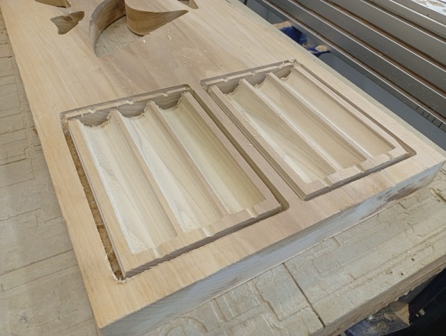
I broke it out manually because the tool wasn’t long enough to cut through the 2” plank I had selected.
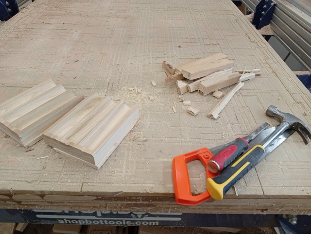
I filed the flutes (proved easier than sanding), but the finish was already very good.
I noticed that the holes again, were not circular. I lasercut a bit of craft foam, and made a shim with the shape of the seam surface, so that when I clamp it up, that will add ~1mm thickness and form a better seal.
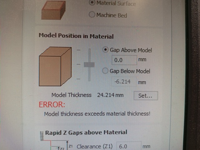
The culprit was the placement of the model in V-Carve. The 3D model, vertically speaking, was at the top of the stock, and even though Z-zeroing with the plate should have been accurate, it would have been possible to move the model down to be certain of the top surface. It seems like it removed very little material from the top.
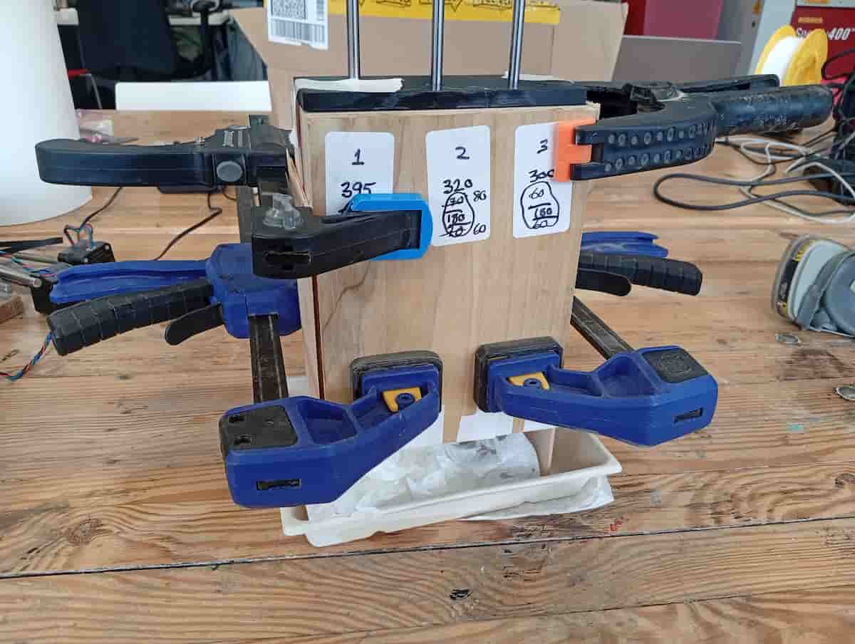
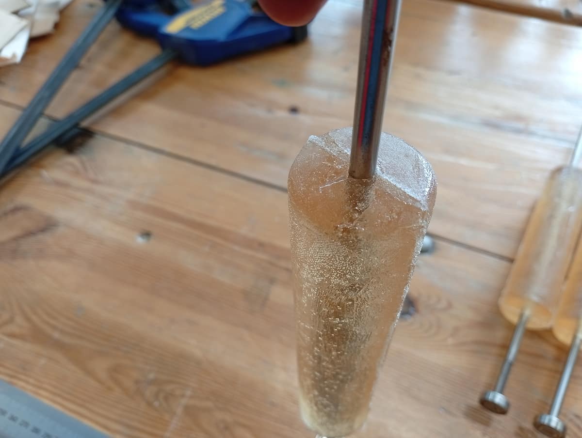
I prepared the mold and measured where I wanted to position the M6 rods vertically. The casts were about 160mm depth, and I left 60mm rod sticking out the mold on the underside.
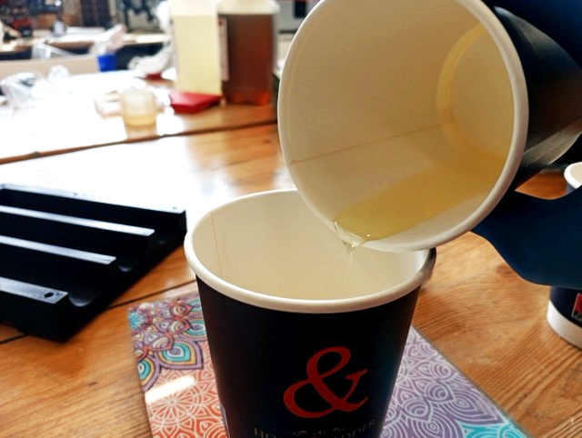
I measured out the same ratio of ( 80g A + 80g B ) x 3, mixed and poured.
I attached a 3D printed cap to make sure the rods aligned.
There was a little bit of leakage. But I think I slowed it better this time.
Demolding was easy.
But, the seam was very pronounced.
But, it’s ok.
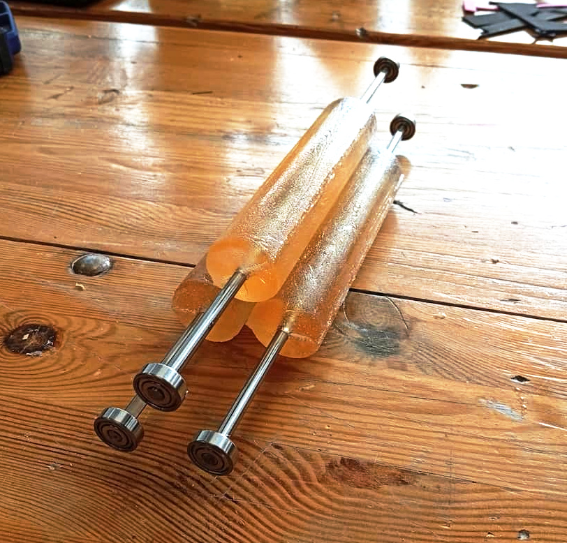
Chealsea (who was in the lab at the time) is wondering why I don’t use ready avalable cylinder, like the PVC pipes that are plentiful and just over there on the shelf. And now, dear reader, I am also wondering this.