Week 10
Assignment - Output Devices
-
Group assignment:
- Measure the power consumption of an output device.
- Document your work on the group work page and reflect on your individual page what you learned.
-
Individual assignment:
- Add an output device to a microcontroller board you’ve designed and program it to do something.
From Assignment Details
Group Assignment
Power Consumption
My board from week 8
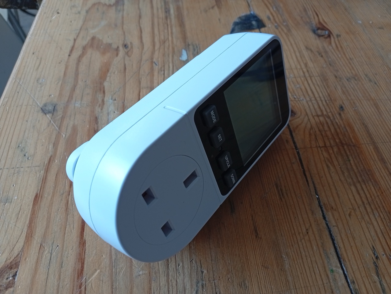
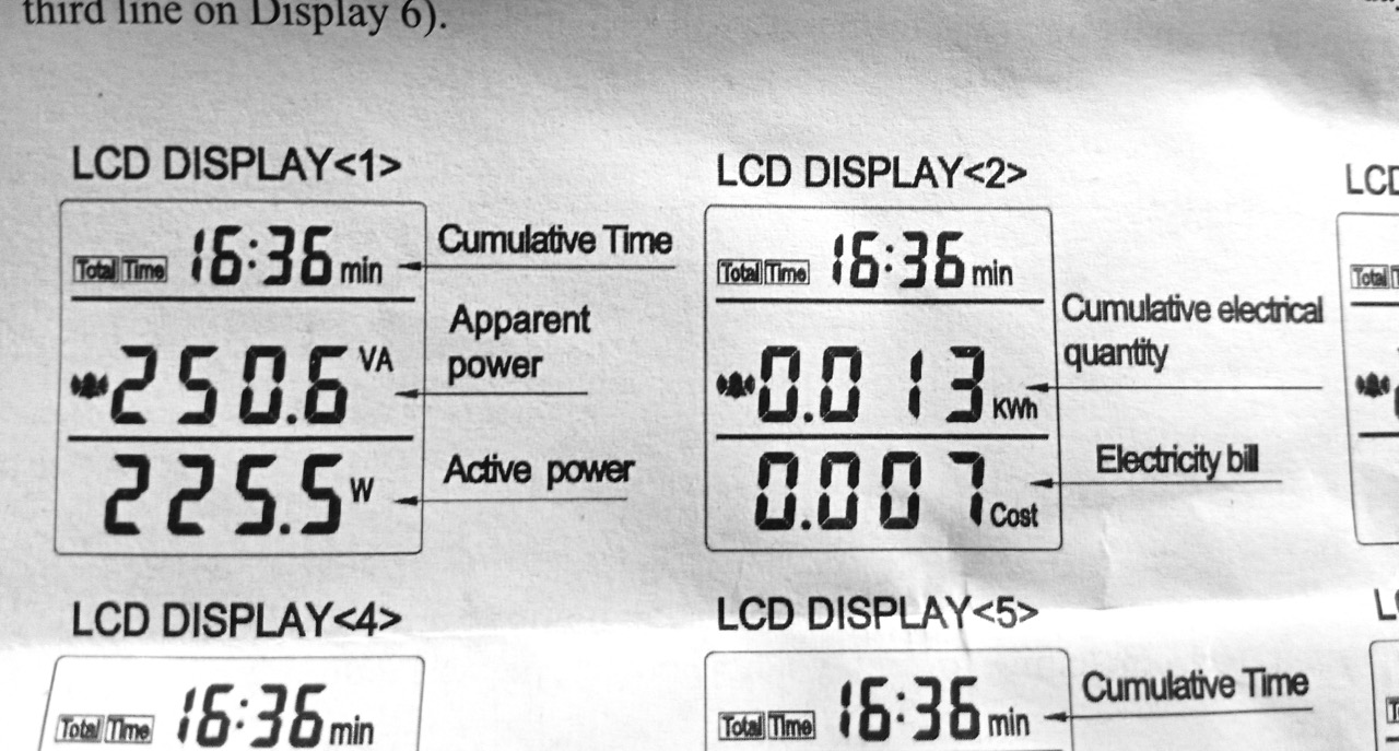
This is a power meter. It measures a devices total power consumption of a device plugged into it, intended for consumer/household devices. It can give Voltage (apparent), Voltage (actual), Current, Watts, Power(kWh) and cost(if you program in your price per unit), and shows Power and Cost. It’s rated up to 230V 13A (Max 2900W).
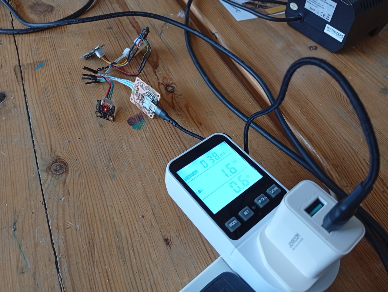
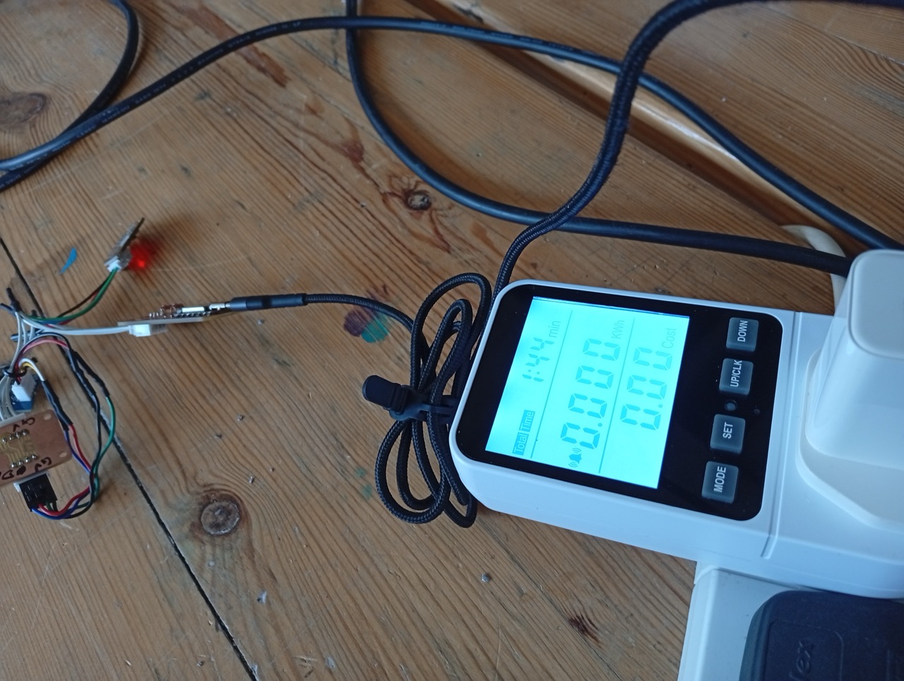
So, the power meter reported 0.6W watts power and 1.6VA (apparent power). And 0.000 kWh. (At 1hr 38mins approx, it’d tick over to 0.001 kWh)
The relationship between voltage, current and power is:
$$ P = V \times I $$
where P is Power (Watts), V is Voltage (Volts), and I is Current (Amps)
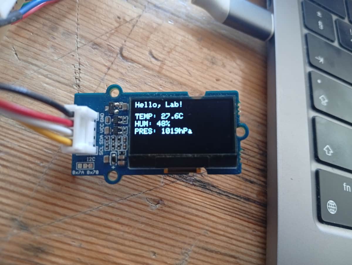
The measured system consisted of the board I designed,
- a Seeed Studio XIAO microcontroller,
- an OLED display,
- and a DFRobot BME280 environmental sensor,
- powered from a 5V USB phone charger.
Multimeter and Osciliscope

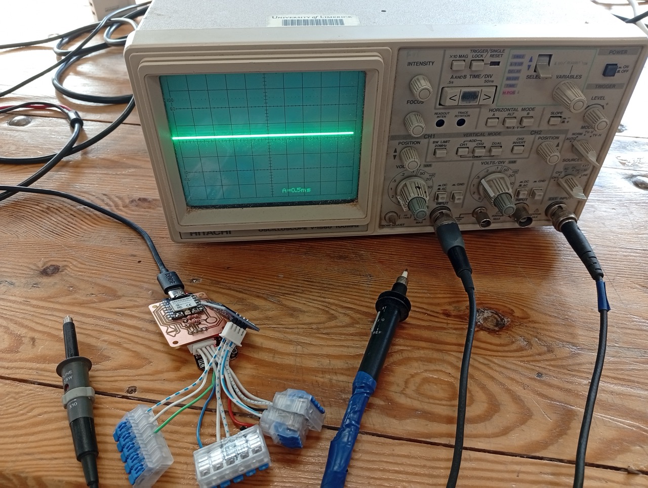
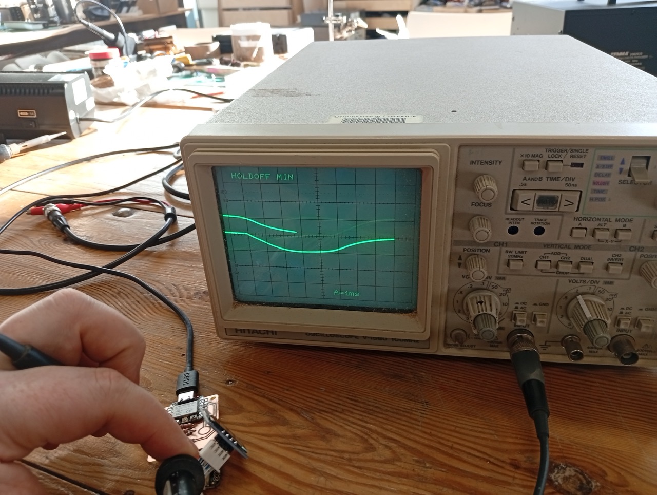
I tested the output of an OLED screen (i2c). The multimeter was to measure to verify continuity and isolation. The osciliscope measured the waveform on modulating connections.
I first measured the pins and board with a multimeter to test what logic level the board was operating at, and used the osciliscope to view the waveform of the CLK line of the i2c. I verified that each device was correctly connected to SDA and SCL, and that the board was sending the appropriate signals.
I set up the osciliscope. I put one probe into the “Common Ground” and one into the “Channel 1” connection. I fixed the focus for a sharp line, and adjusted vertically until the middle of the curve was in the centre of the screen. I changed the “Range” knob and the finer adjustment. The osciliscope had an “Auto” frequency button, so I could set that, and adjust to decrease and increase from there as required.
My board:
I tested the output of an OLED screen (i2c).
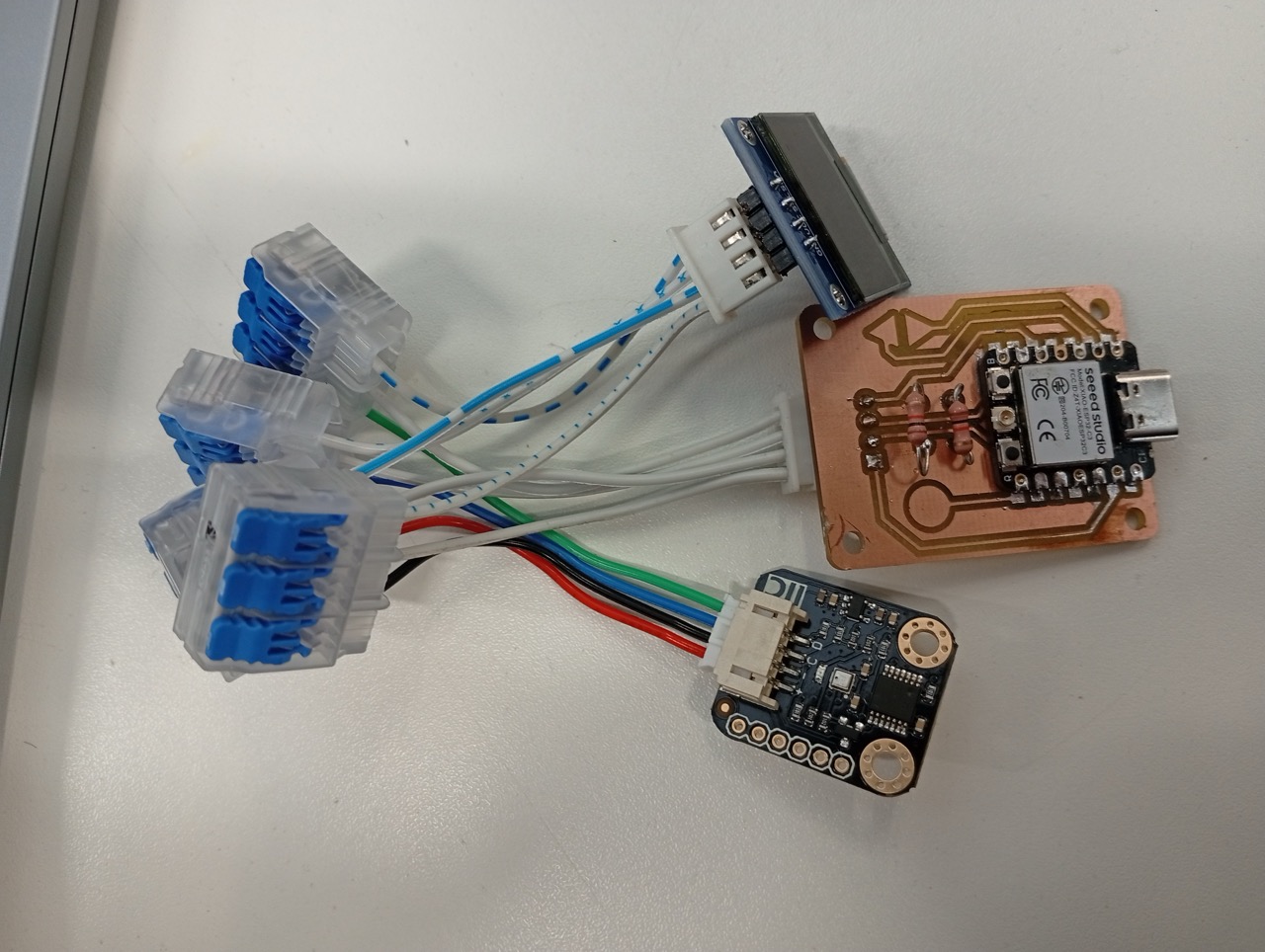
Unfortunately, time was short and I used these Wago connectors to save me having to resolder the connecting cable. I made a patch board in the end, which swapped the order from Grove to other i2c in the end.
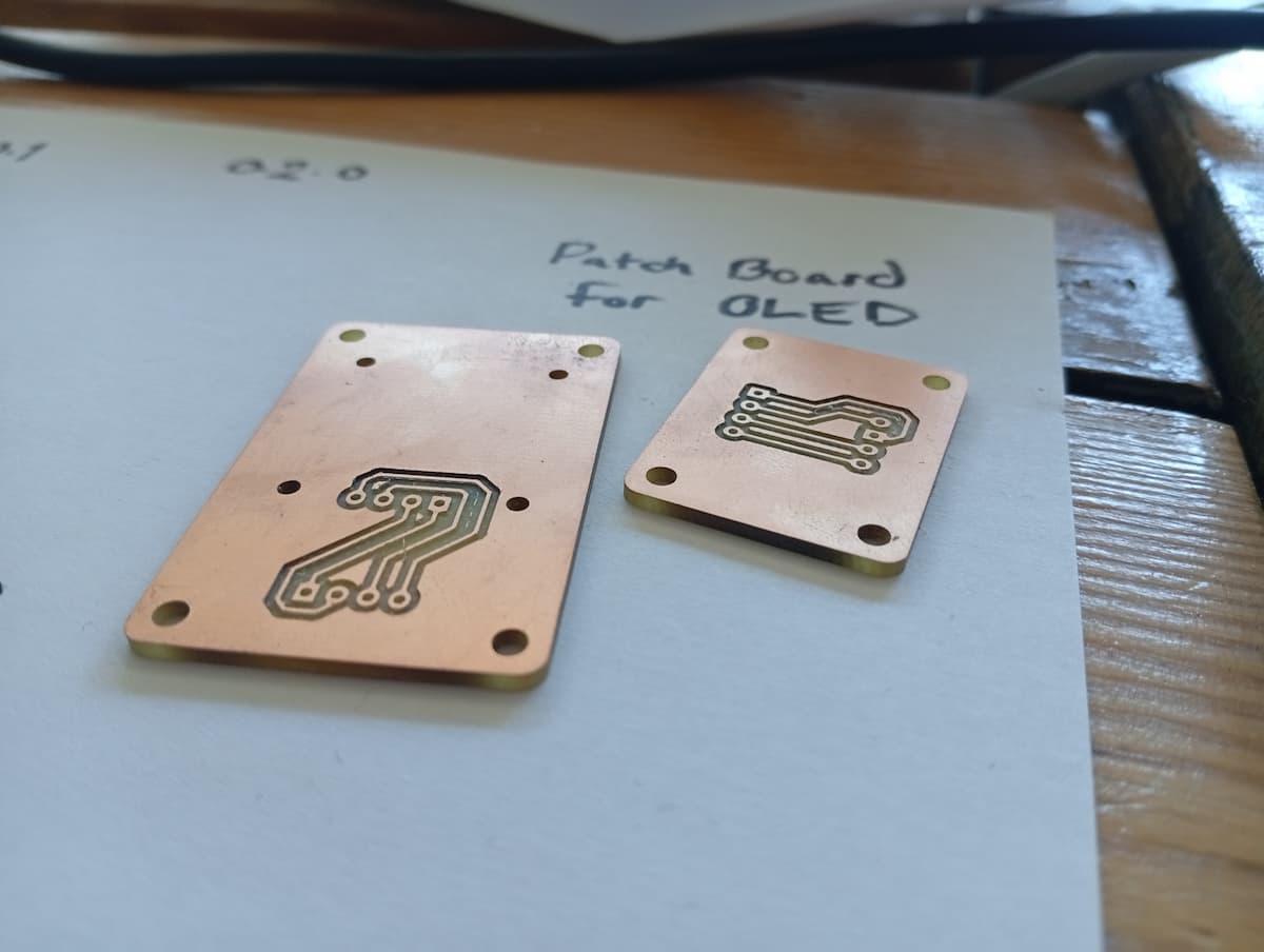
Little Patch Boards from week 8,
Different Waves:
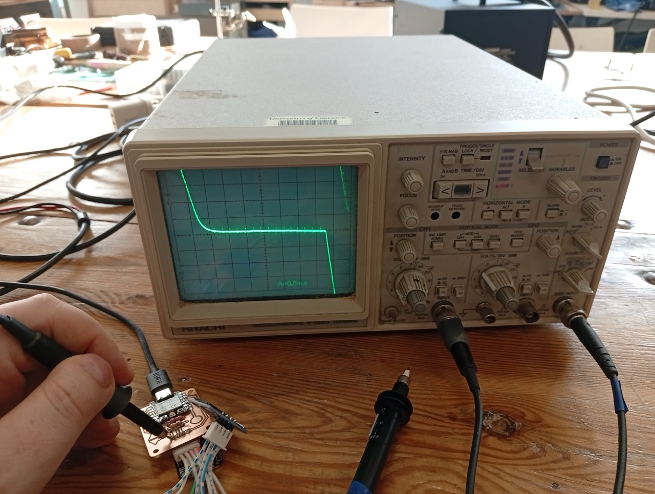
What it was programmed to do:
Reflection
In this assignment, I used a multimeter. I learned more about the Osciliscope and Power Meter. And basics of power and impedence.
I had to improvise with off-brand Wago connectors and a small adapter board to avoid resoldering cables, but I managed to connect an output device and test its connections.