Version 0.2/3
Version 0.2
This version will introduce material handling. I will build a small machine that can be placed inside a laser cutter. It can unroll paper, and either roll up the output or deposit it to the side. I will use a wireless microcontroller, and drive at least the stepper motor.
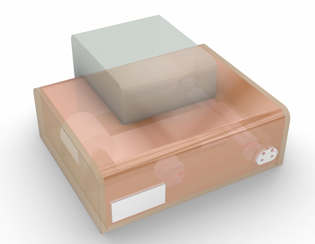
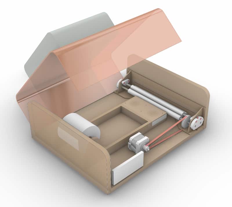
Version 0.3 sketches
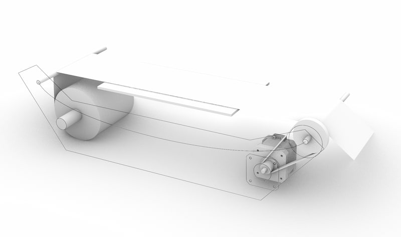
I decided to update my sketch 3D model with developed parts, and to add parts, eg. enclosure and space for the laser module in order to reasses where I am.
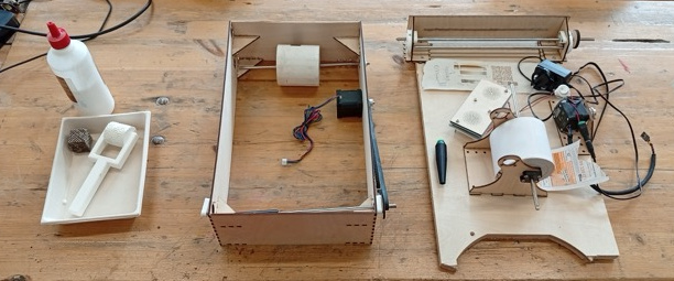
V0.2 and V0.3
V0.2 and V0.3 got a little mixed, due to deliveries and other issues. Documenting chronologically, not by version, didn’t help! To compare, this is what they look like beside each other:
Mechanical
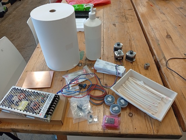
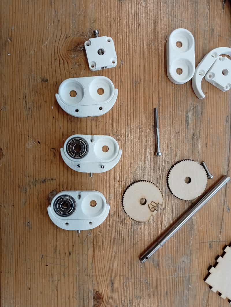
Gathering new parts
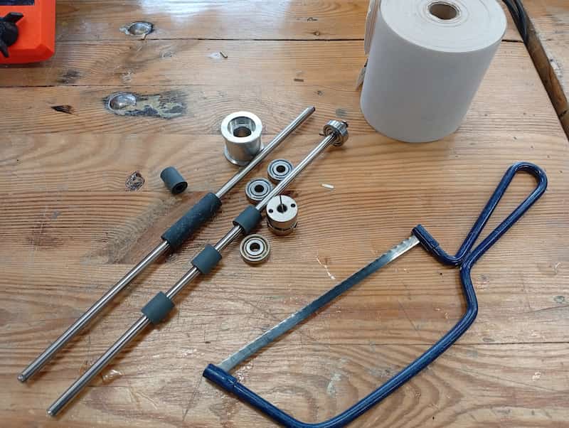
I got some salvaged parts from a friend that recently did a printer disassembly. and some matching bearings and a coupler. I don’t have pulleys etc. to match, but I have some toothed-belt left over from machine week and will design some custom parts.
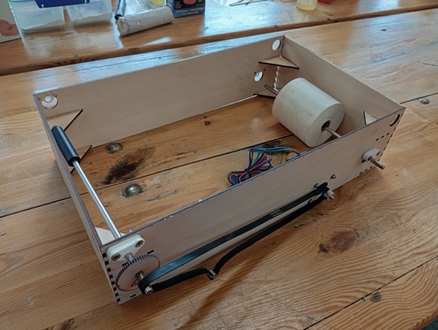
Making a Lasercut Enclosure (v 0.2)
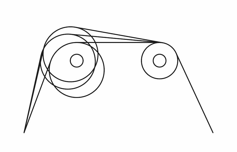
Notes for drawing a box: * 19mm bearings (test concludes: 18.8mm laser cut holes). Have 8. * Rods are 254mm M6 (some with rubber rollers already). * Bearings are 6mm thick, so a max. internal depth of 242mm. * The receipt paper roll is diameter 80mm. * Motors are Stepper, Nema17. All have 5mm bores. * Laser Pulley (Boxes.PY) * Belt is 610mm loop, GT-2,
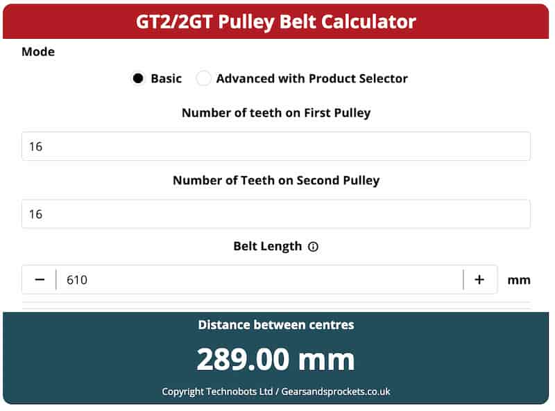
Used Pulley Calculator. Gonna go 1:1 to start, so 30teeth:30teeth gives 275.0mm centres. One gear is lasercut, because I don’t have the part.
(also 60:30 would be 259.82 mm)
Updating the test 3d model above with these measurements gives this sketch (side panel):
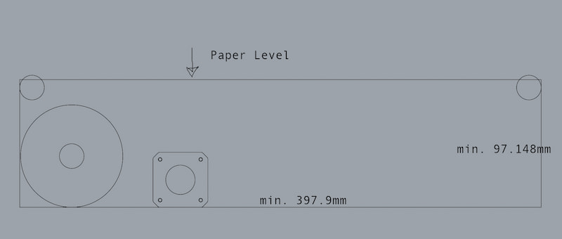
- Gonna give it a little more width(say, 405mm), but keep the height to the minimum.
- Plus our depth of 242mm.
With a little modification, I’m gonna do a quick box based on the ElectronicsBox, by Boxes.PY.
Files
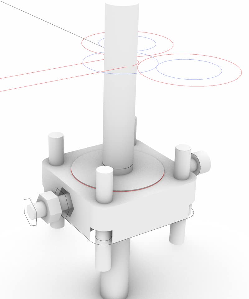
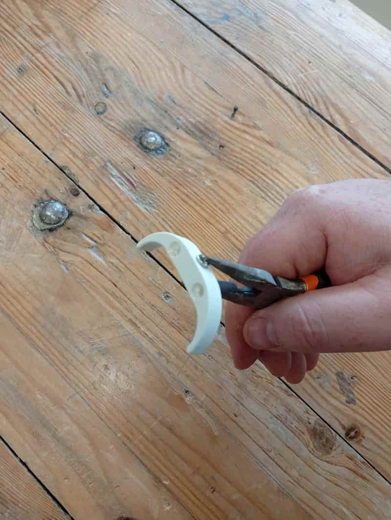
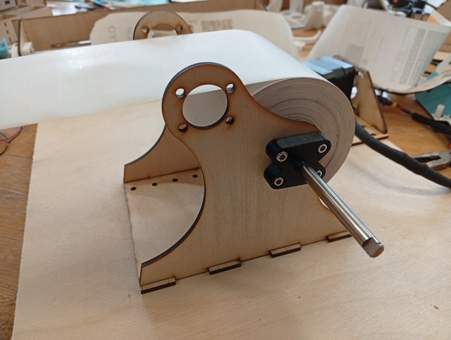
“The Crux” (3D-Printed fixtures for the Bearing and the Rods)
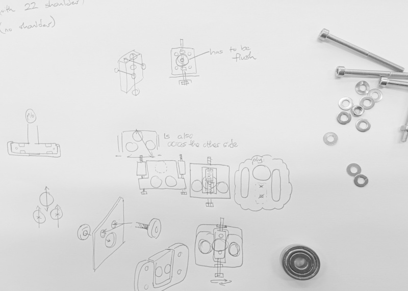
This part is a 3D-printed connector for bearings that allows for finer adjustment for the wheels that hold the paper.
Sketch model:
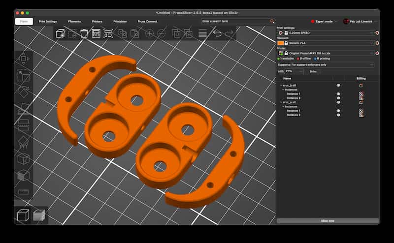
Files (3x STL files):
Need to try overhanded to avoid collision with toolhead
Updated the paper holder:
This version still makes it pretty difficult for a user to change the roll!
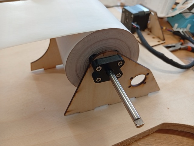
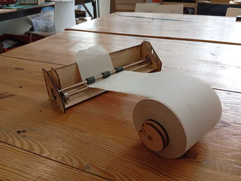
Making the Rollers
I think first version of the ElectronicsBox.svg file didn’t actually have contact wheels that would actually pull the paper. I want to add wheels as above, but would two be adequate? I will redraw the sides with these adjustments. Possibly I have to put the rods closer together than the bearings would allow as is.
The rollers serve a number of purposes, alignment, tension and spreading out forces. Also keeping the paper away from the greasy metal rods. I think it could be a good candidate for casting rubber… The salvaged rollers were diameter 11.8mm on an M6 rod, but to fit with bearings, I’ve made this one 15mm diameter outside:
- m6_test.stl (6.3mm worked).
- roller_rubber_15d44.stl
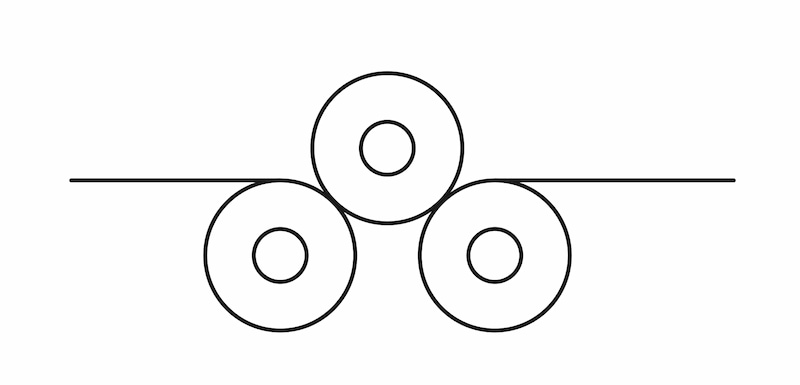
I was imagining an eccentric wheel like below, whether this would be any good to help with focusing, or leveling. Maybe this on both sides?
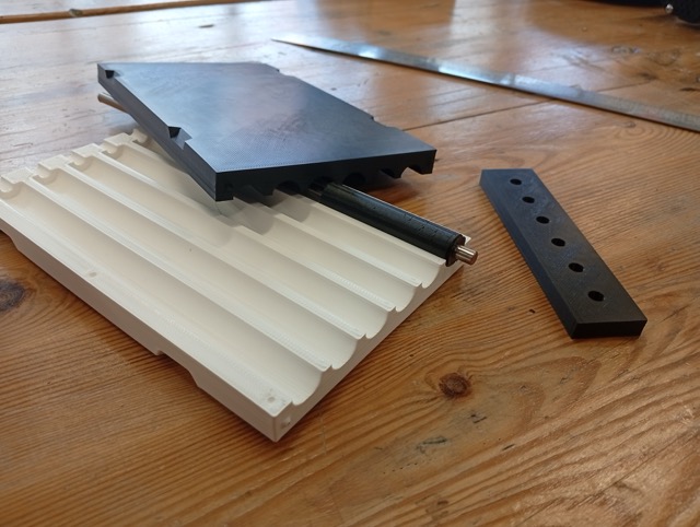
Because I’m not sure how to distance the different rollers, I’m gonna make a quick test… it’ll kinda look like a clothes/laundry mangle, I guess.
Flexn’t
Printing cylinder in TPU was wobbly. Maybe will use some casting rubber left over from week 13, in a mold like this (M6 inserts, cast while vertical, top for rod alignment, nubs for alignment, notches for zipties):
3D Printed Molds
Printed (14mm version):
But are not round:
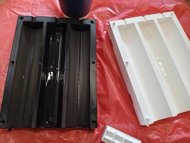
It was quite leaky:
??????Result image???
Conclusions
- Likely didn’t leave the XTC for long enough (pulled off).
- No release agent. Damaged on getting it out.
Files
????? Files 14mm and 35mm versions ??
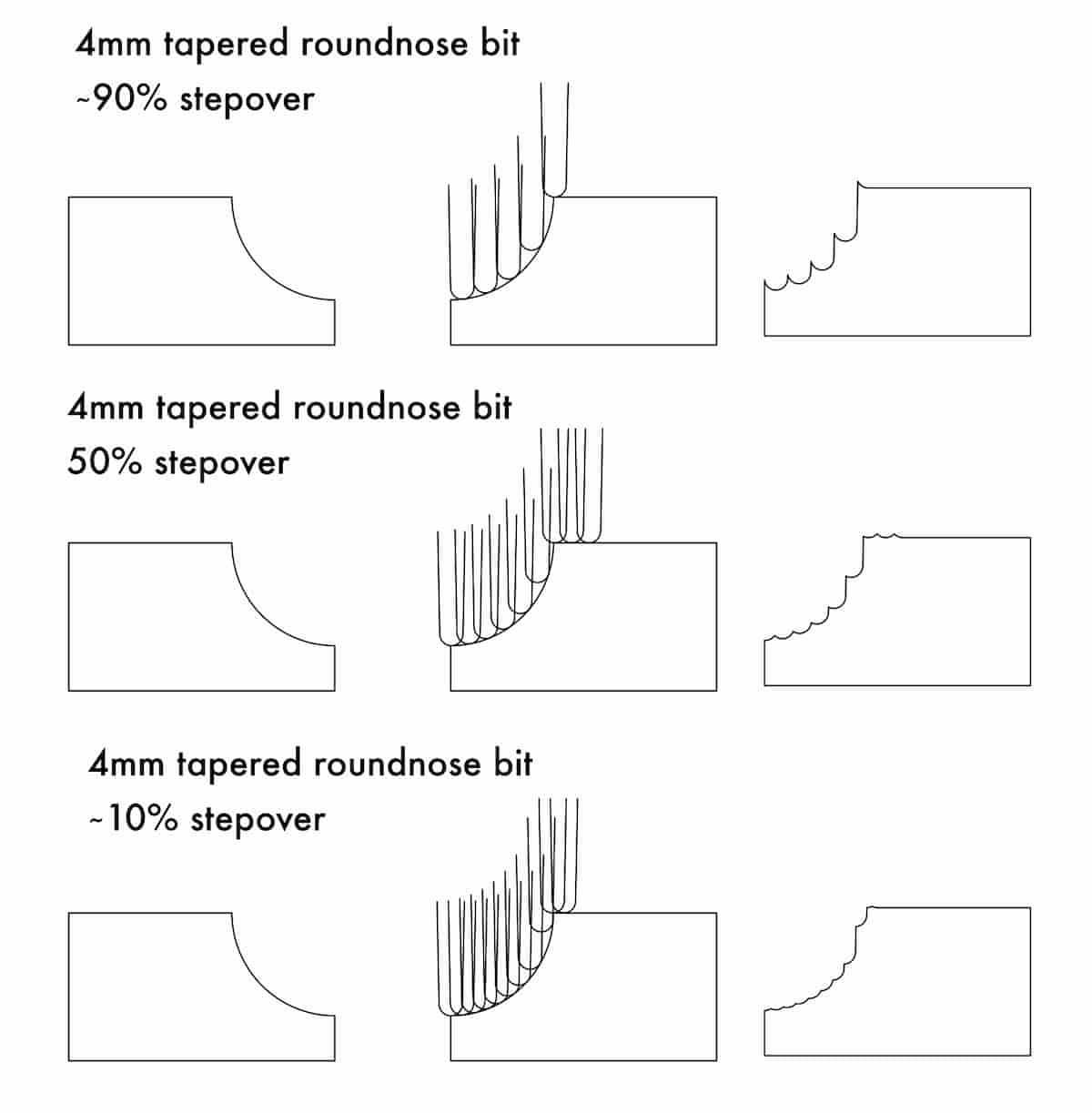
So, should I switch and make it in the CNC? (Ignore the Stepover numbers. I tried to calculate it, and set the dimensions in Inkscape, and I think the % looks pretty off, but it still has the general idea…)
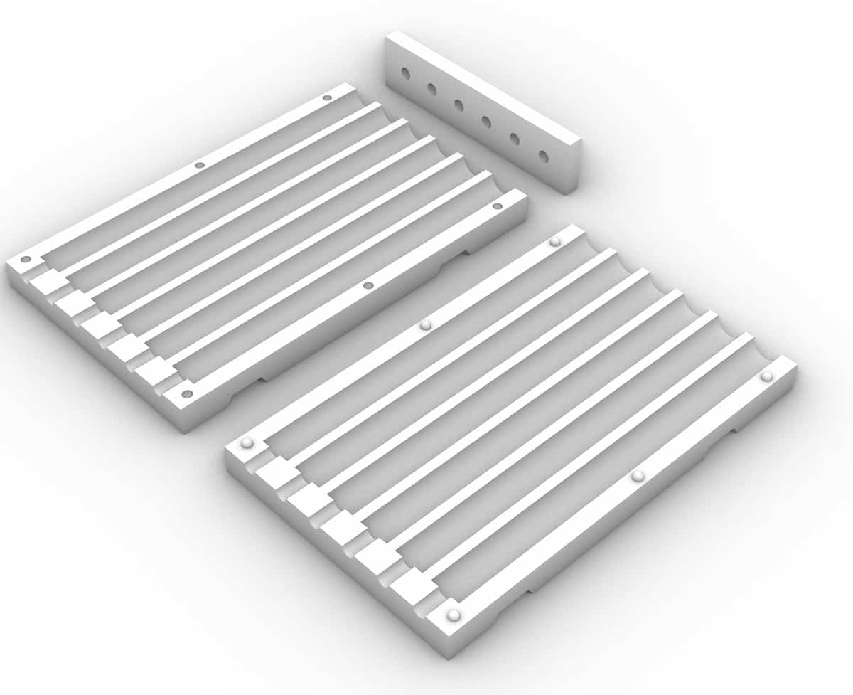
Wooden Mold (Attempt No. 3)
I redid the mold in timber to try again.
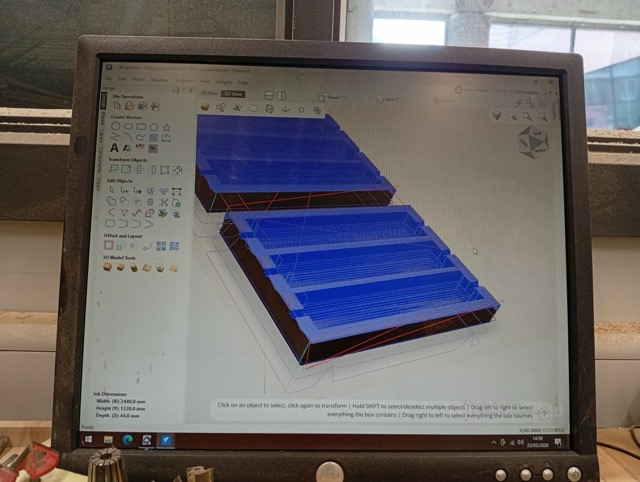
I milled it on the CNC, so I exported an STL, and imported into V-Carve Pro, and used 3D toolpath options (Roughing and Finishing, with a Downcut 6mm and a Tapered Ballnose 1/8”).
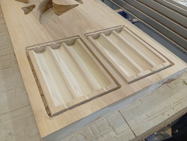
I broke it out manually because the tool wasn’t long enough to cut through the 2” plank I had selected.
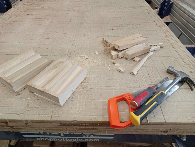
I filed the flutes (proved easier than sanding), but the finish was already very good.
I noticed that the holes again, were not circular. I lasercut a bit of craft foam, and made a shim with the shape of the seam surface, so that when I clamp it up, that will add ~1mm thickness and form a better seal.
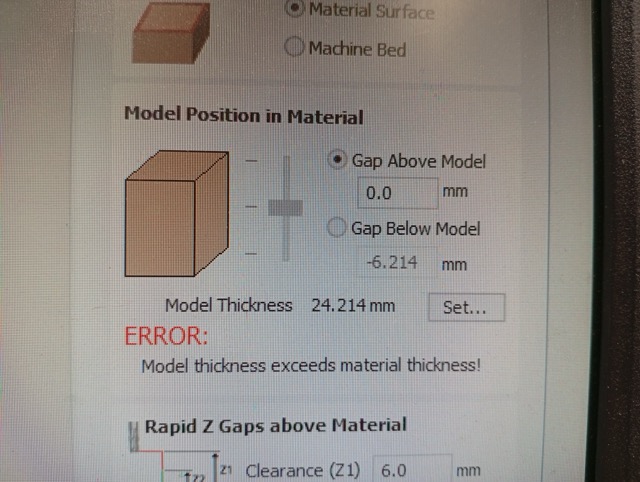
The culprit was the placement of the model in V-Carve. The 3D model, vertically speaking, was at the top of the stock, and even though Z-zeroing with the plate should have been accurate, it would have been possible to move the model down to be certain of the top surface. It seems like it removed very little material from the top.
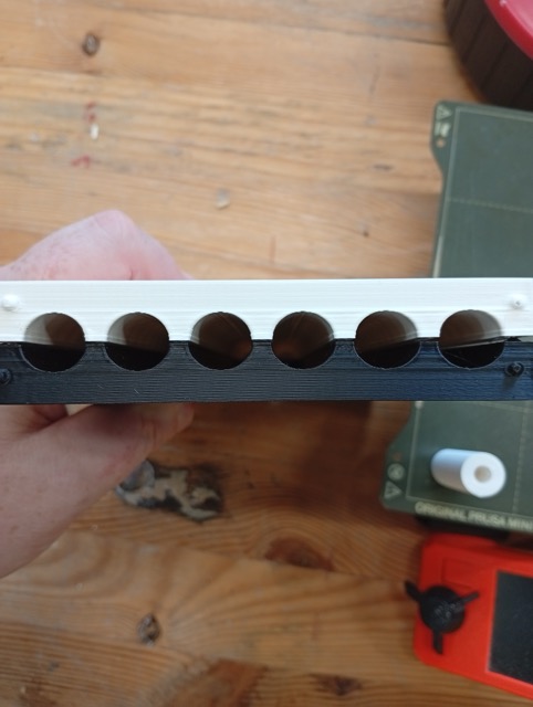
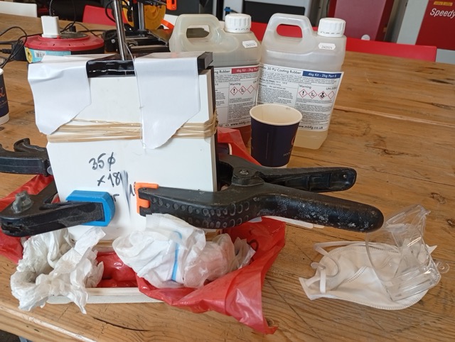
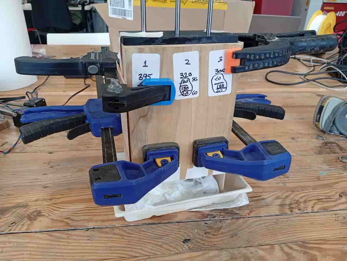
I prepared the mold and measured where I wanted to position the M6 rods vertically. The casts were about 160mm depth, and I left 60mm rod sticking out the mold on the underside.
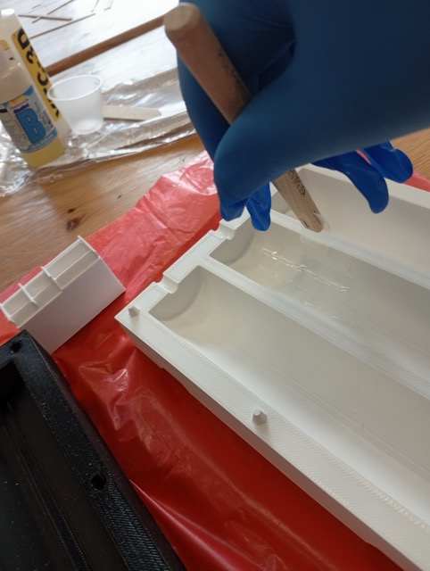
I measured out the same ratio of ( 80g A + 80g B ) x 3, mixed and poured.
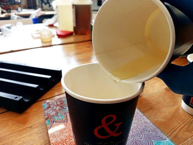
I attached a 3D printed cap to make sure the rods aligned.
There was a little bit of leakage. But I think I slowed it better this time.
Demolding was easy.
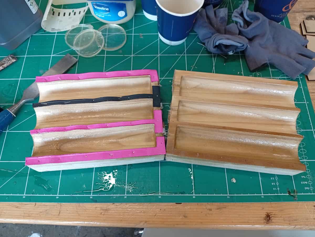
But, the seam was very pronounced.
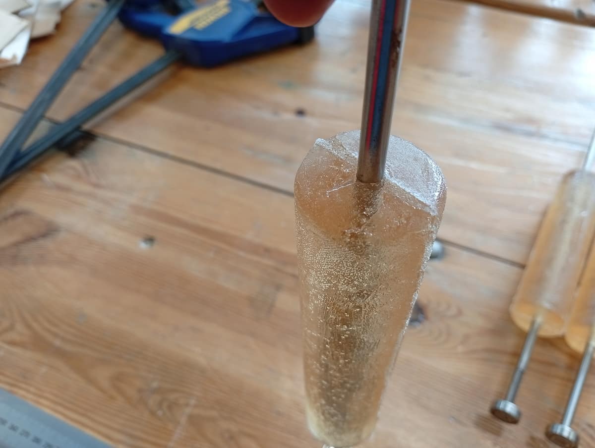
But, it’s ok.
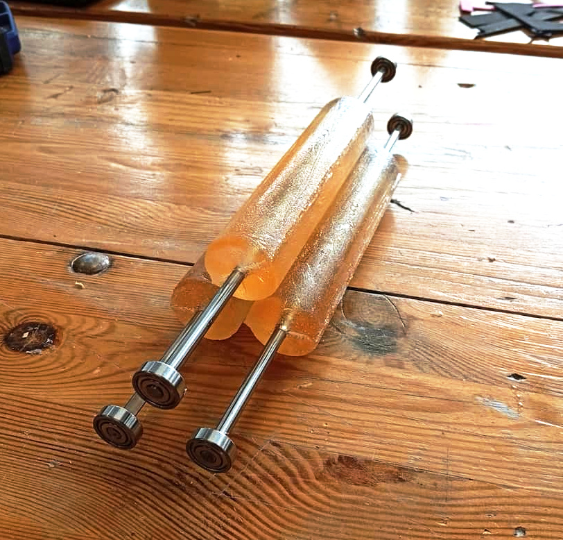
Chealsea (who was in the lab at the time) is wondering why I don’t use ready avalable cylinder, like the PVC pipes that are plentiful and just over there on the shelf. And now, dear reader, I am also wondering this.
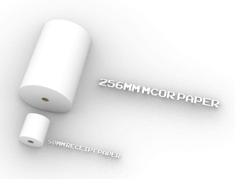
Paper
Measured up some paper:
Making a wider Mangle (Boxes.py and Inkscape):
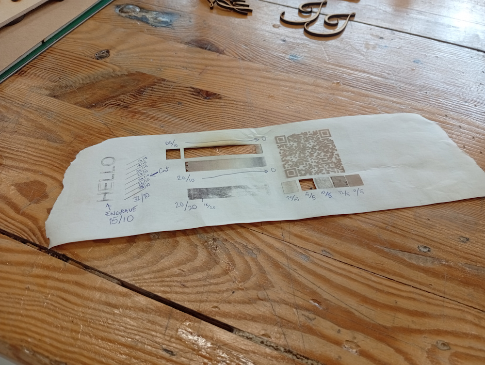
Test engraving the paper
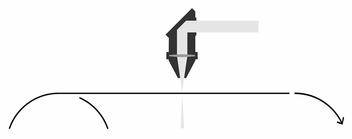
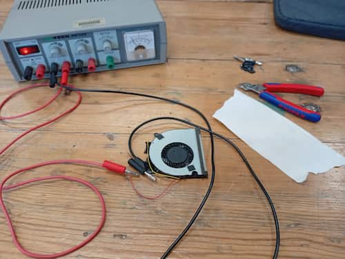
Centrifugal vacuum table (v0.3)
The plan is to use the small vacuum table as a break, to keep the paper from doing this:
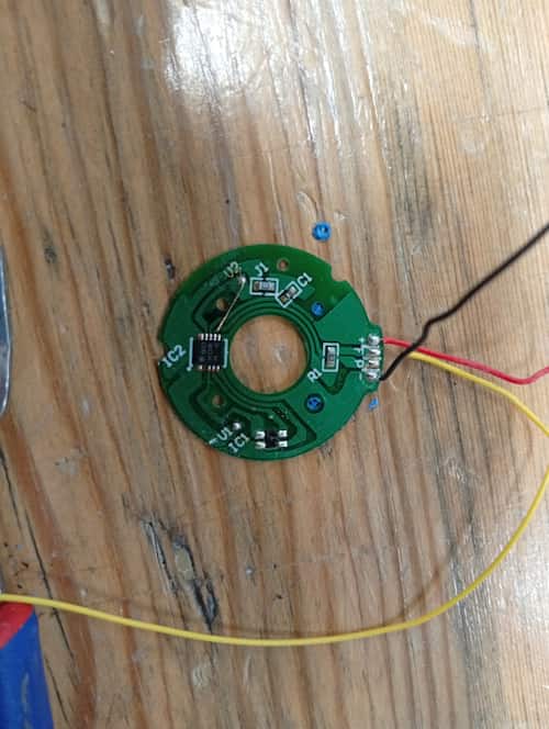
I had a few old centrifugal fans taken from laptops. It has 3 wires, red(+), black(-), and yellow. It works with only red and black connected to the desktop power supply thankfully. Yellow probably takes a PWM signal.
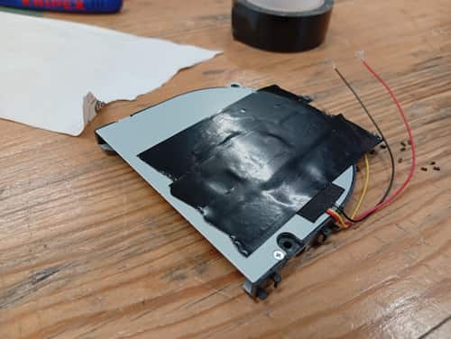
I discovered this design, which is open on both sides, pulls air from both sides. I taped over one side. I tore off a bit of paper, it lifts, and releases as I changed the voltage. It’s not a very efficint way to do this, and leaks probably didn’t help, but good experiment.
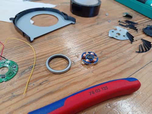
It says “5V DC” on it, but I got to into my test and gave it a bit too much. So this turned into a good opportunity to open it up and have a look! (and I got a cool magnet and motor part out of it)
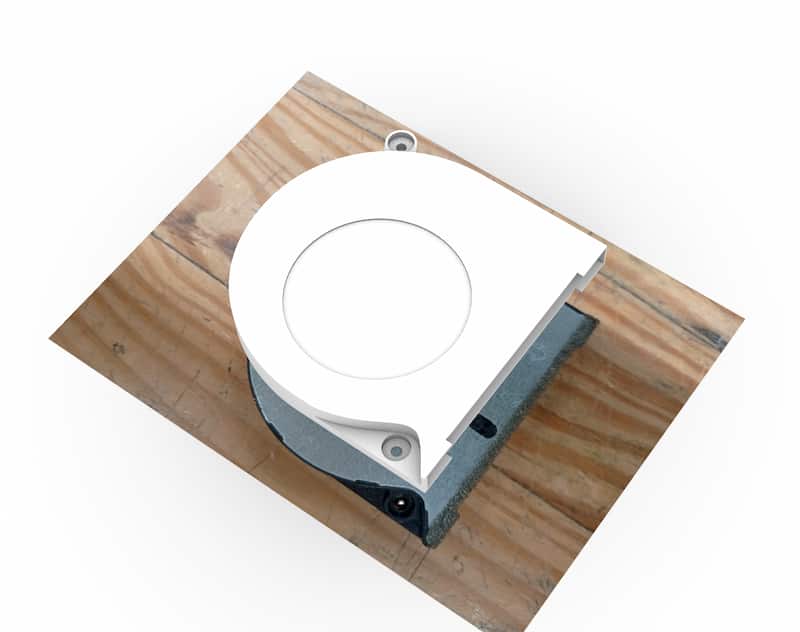
I measured up another fan in Rhino, and used a referenced photo to get rough shape, but only some dimensions are needed to do the mounts and rubber gaskets.
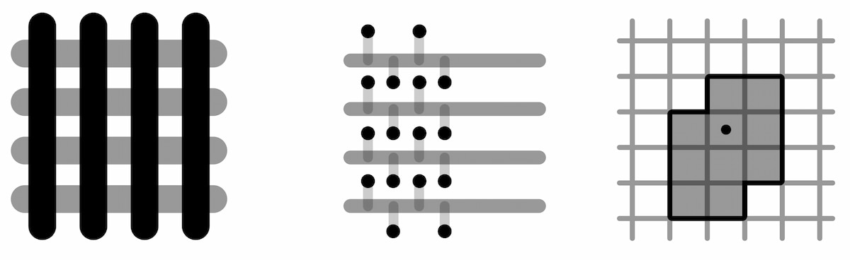
So then I made a pattern of holes, spent a little longer doing it in Grasshopper, for some reason:

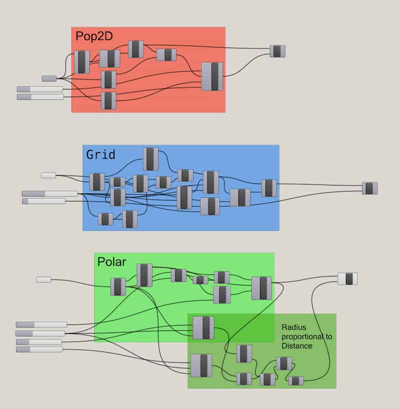
Grasshopper Script Download:
This is the overall assembly with the gasket ring, being of lasercut rubber.
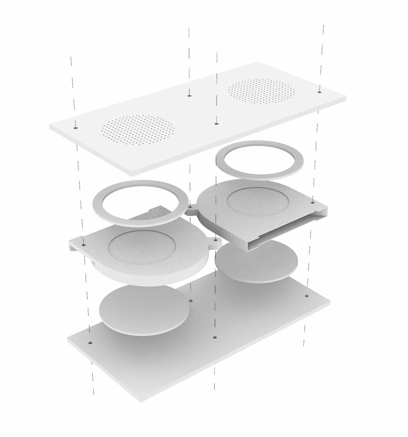
I used the bolts to align and tightened the gaskets in place.
- there were small, visible gaps
- tightening squeezed the fan structure, and didn’t spin!
- I didn’t do anything to countersink the bolts, which would be an improvement.
- Ultimately it still worked, but is not very strong:
Conclusions
- Not super strong. Mightn’t have to be.
- A second layer could help increase the area. Some pattern - I’m imagining those trivet designs for example, CNC cut coasters. Maybe some pattern based on that.
- Seems industrial vacuum tables use a movable gasket ring that fits the tracks of the table.
Software
Python Test 2
Again I used ChatGPT to try something in Python, using Trimesh.
I asked it to create a virtual environment, and to remove a number of dependencies I didn’t recognise.
Dependencies install with the install.sh script. Without, it’s 22KB vs. 143MB.
- project.zip,
- Sample output: slices.svg,
- chatgptlog_makepython_20260511.txt.
Conclusions:
- Install method is cumbersome. AI probably understood because I mentioned that it should have an install script and a run script, that it needed those, when it should have just had those methods.
- tkinter drag and drop works. There is not feedback.
- Preview is wireframe from above. Better would be something isometric, with superimposed cut planes.
- Output did not write new file over old file. Doesn’t seem to increment filenames, doesn’t overwrite by default and doesn’t indicate anything to the user!
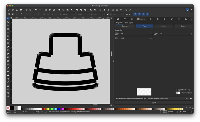
- Output file wasn’t usable. It was technically an
SVGand it opened in Inkscape. There may have been a huge scaling miscalculation, but because it only saved the first file I didn’t look enough to check. Cuts didn’t have outer box, registrations, breaklines or cut numbers. - I hoped my python would have been better, but I cannot check the whole
app.pyfile unfortunately. I will probably go back toP5JSwhere I feel more at home. :(
Can a laser push a button
If so, perhaps it can signal the end of the job?
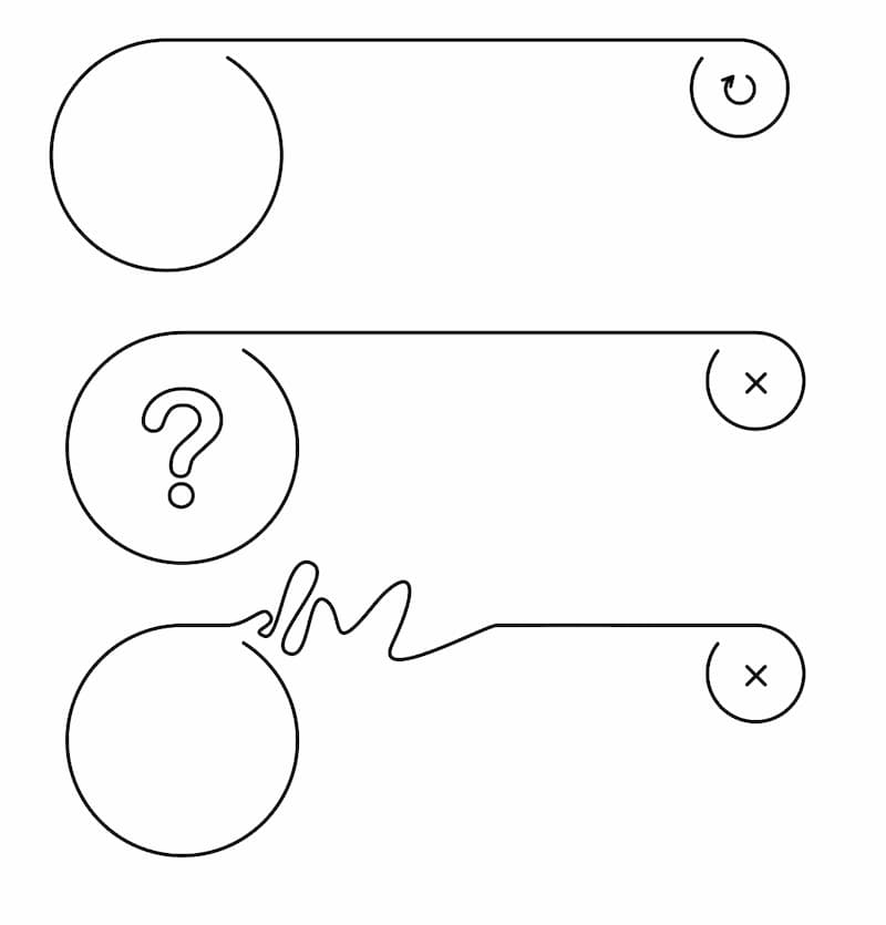
PenPot for Low Code Interface Design
PenPot is a program for designing UX/UI projects. It is open source, and free as an individual. It’s similar to Figma and Sketch. You use it to make “paper website”-type mock-ups of apps and websites, if you want to start with the design.
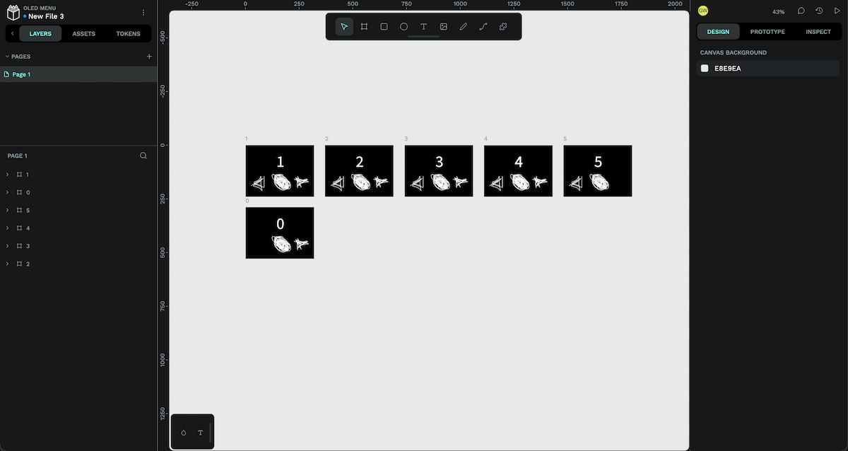
Tbh, this was an idea if it worked, but using the LVGL library etc. is proving difficult with many errors. It prioritises touch and click interfaces, so maybe there isn’t much value in this workflow right now.
P5JS
- my code (opens in P5JS online editor)
P5JS References:
- “Image Drop” example. Revised version by Kasey Lichtlyter.
- createFileInput
- chatgptlog_makep5js_20260526.txt
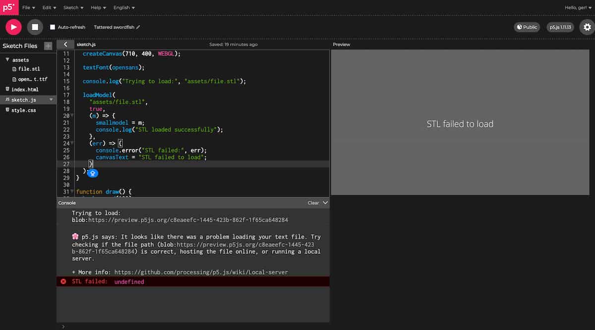
It started well enough, but when I hit a snag, I asked ChatGPT. It told me that, if you use loadModel for STL’s in P5JS, it calls threeJS, and because I want to show it in WEBGL, together, all that is unstable. Covering for itself.
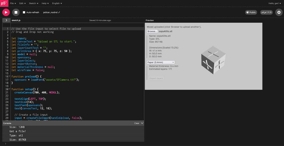
So, I start again, and I build:
P5JS CHATGPT LOGS:
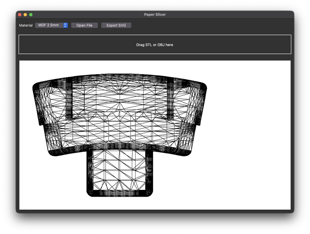
At the moment, this does not use a dedicated library to handle mesh files like trimesh in Python, it just uses the built-in P5JS and WEBGL capabilities. The preview is limited, and to split a 3D model with any number of triangles would be quite expensive this way. (I have disabled the Export button, because it doesn’t actually do any slicing yet).
It is also limited to ASCII STLs and not Binary! (Probably also alleviated by use of a library).
…Drag’n’Drop still doesn’t work.
But you can play around with it:
Idea
Make a FreeCAD Macro?
Electronics
3D Print Button( Holder)s?
I made this Handheld Button part by @aidtopia_261573.
…modified for 12mm buttons:
PCB Design
Seperating features into v0.2, v0.3, etc.:
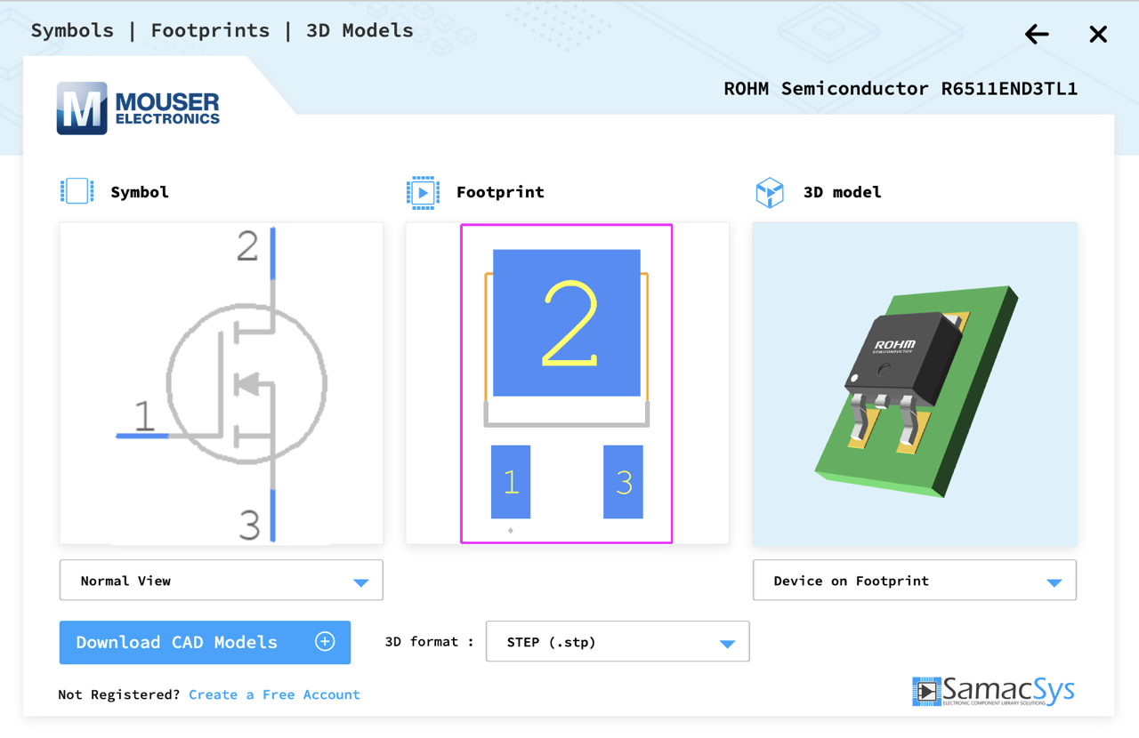
I set up a new project on KiCAD, and I started gathering and searching symbols and footprints
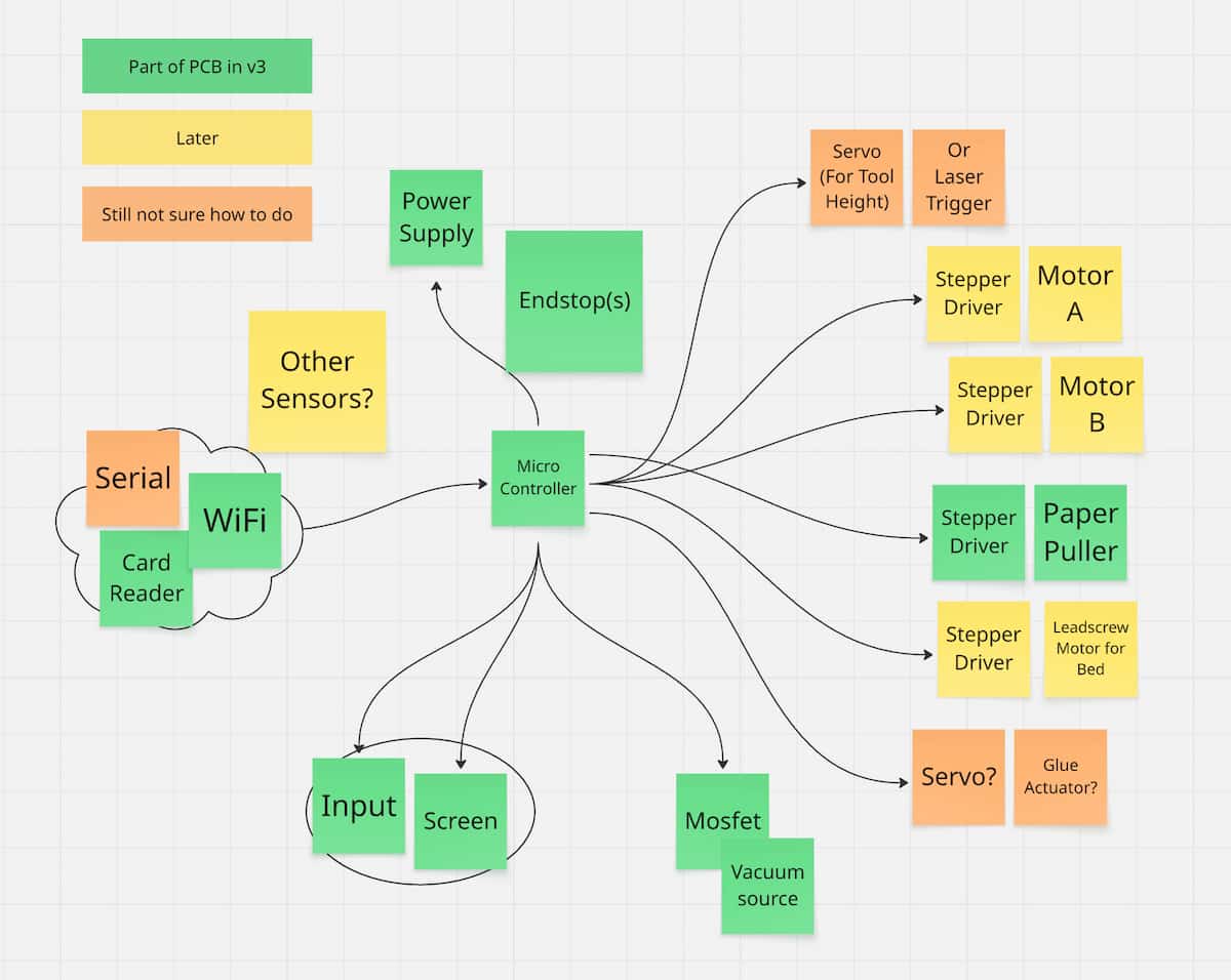
I used various sources to come up with a schematic diagram (with AI help).
But it looks like I’m going to be short of pins. What I have so far:
- 3x Stepper Motors = 6 GPIOs minimum
- SD Card Reader MOSI pins… some GPIO’s?
- MOSFET for Vac Table = 1 GPIO
- 4x Buttons = 4 GPIO
- 2x EndStops = 2 GPIO
- Trigger for Laser Module = 1 GPIO
I started looking up ideas around MultiPlexing, search and GPT. Based on something I found on Hackaday (which the person who posted it, called it a Resistor Ladder) and another linked from the Arduino forum, I drew up two ideas:
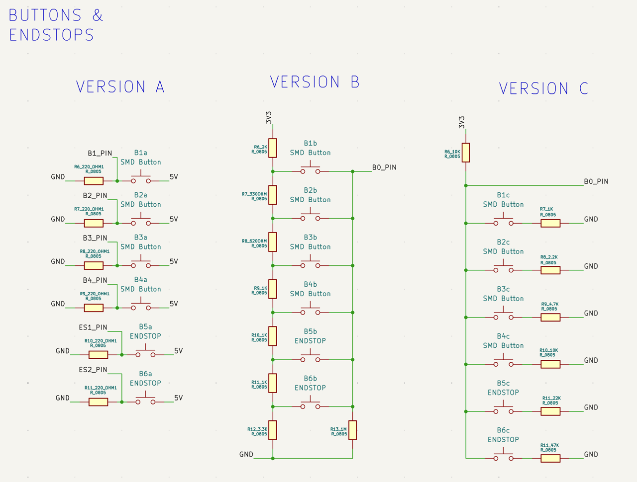
To visualise it, put it into GIMP (Export As > whatever.gif > As Animation):
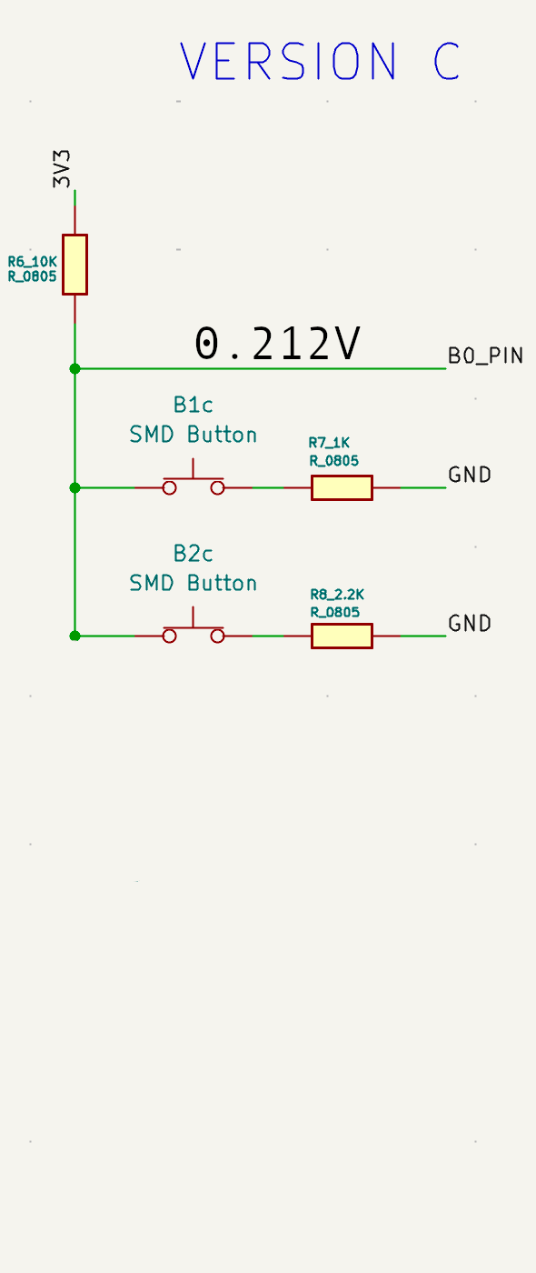
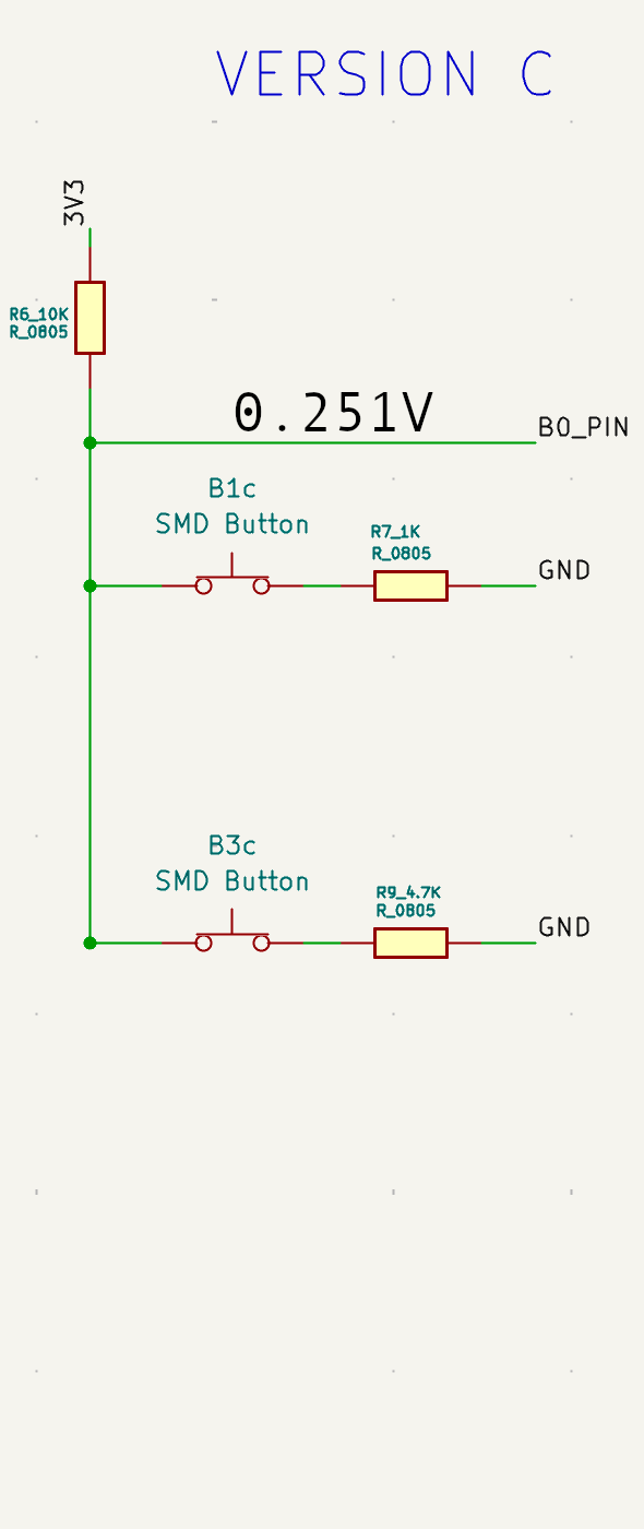
So, what happens if you press more than one button? You need the Analog pin to be stable, of course, and the restance values you use to be distinct, so you get a clear voltage, and you can compare it.
$$ V_{out} = V_{in} \times \frac{R2}{R1 + R2} $$
For example (1st button pressed only)
$$ V_{out} = 3.3 \times \frac{1k}{10k + 1k} \approx 0.300V $$
I remember
V = I * Rfrom Physics, but I didn’t remember how to apply to this situation. (So, please forgive my use of ChatGPT, to refresh my memory).
| No. buttons | 0 | 1 | 2 | 3 | 4 | 5 | 6 |
|---|---|---|---|---|---|---|---|
| No. permutations | 1 | 6 | 15 | 20 | 15 | 6 | 1 |
CHATGPT LOG:
Custom PCB as Shield for a larger Microcontroller?
Started with a breadboard
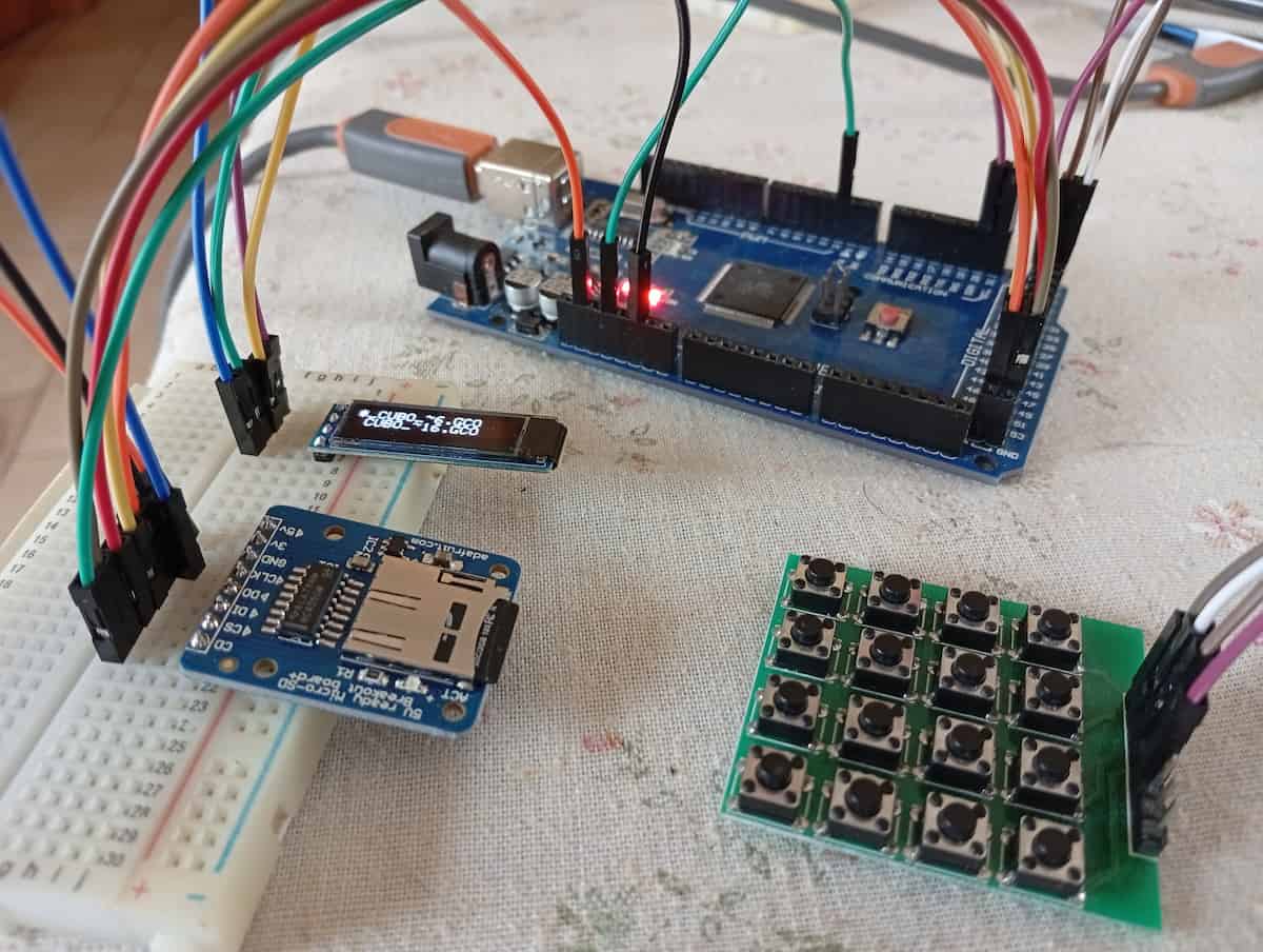
What has been super useful is virtually testing on Wokwi. In fact, if you click your diagram.json tab, you have your wiring layout in a way that you can copy and save, and ask AI to have a look at.
Separately, I was able to get working,
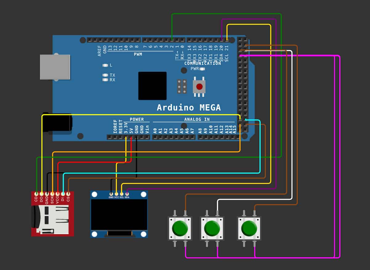
And,
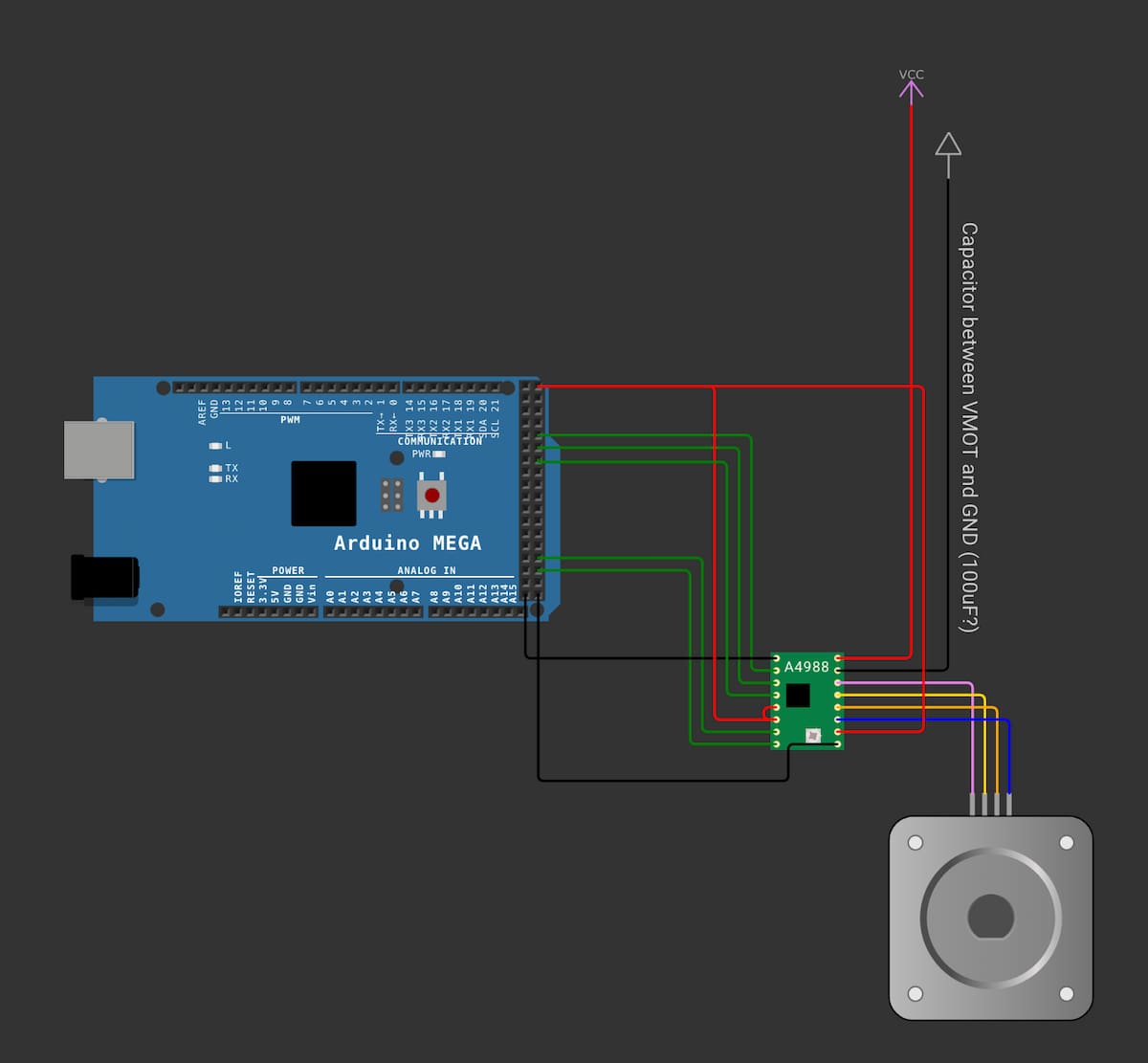
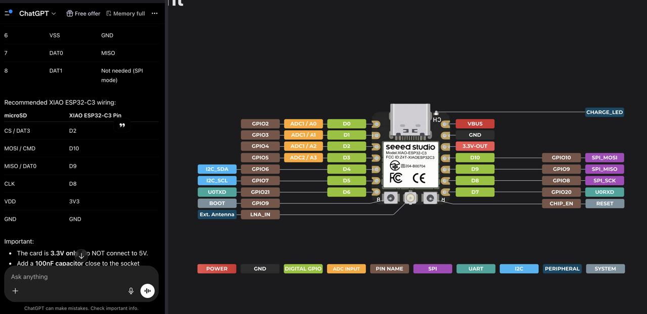
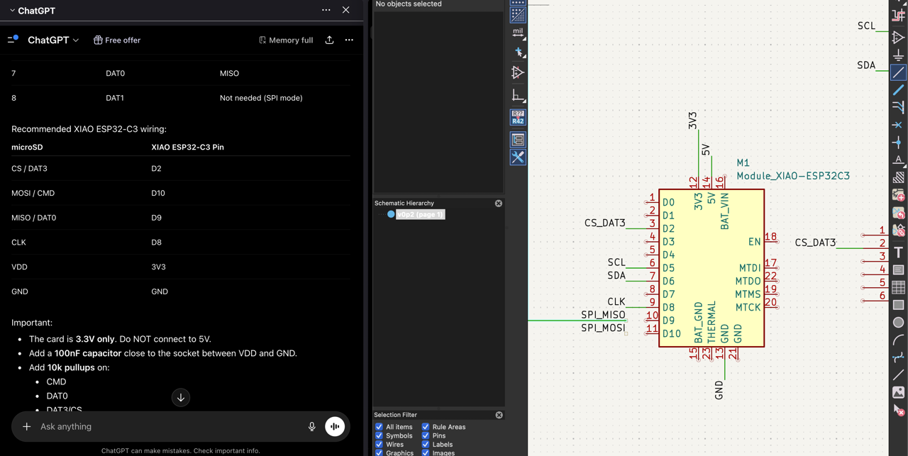
And I wanted to merge them, and I asked ChatGPT to help match the list of pins:
Official Arduino 2560 page, and click CAD Files. Unzip, for the .brd and .sch. Go to File > Import > Non-KiCAD Schematic.
From their PDF, I placed the drawing of the board using Place > Place Reference Images.
Picked out some PinHeaders, (1No. 2x18,1No. 1x10 and 5No. 1x8)
- KiCAD Align, and Distribute, to get it as close as possible using the smaller grid settings.
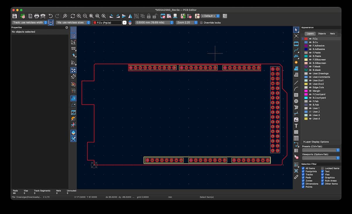
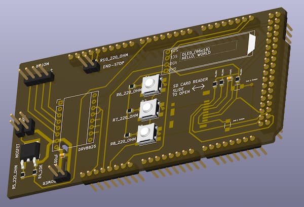
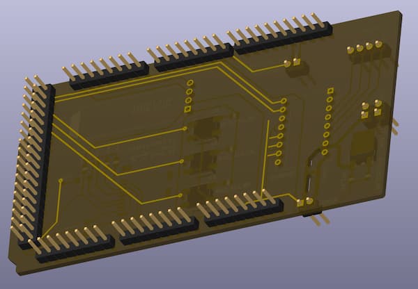
Here is the PCB file (a template to make a shield out of):
And the populated version,
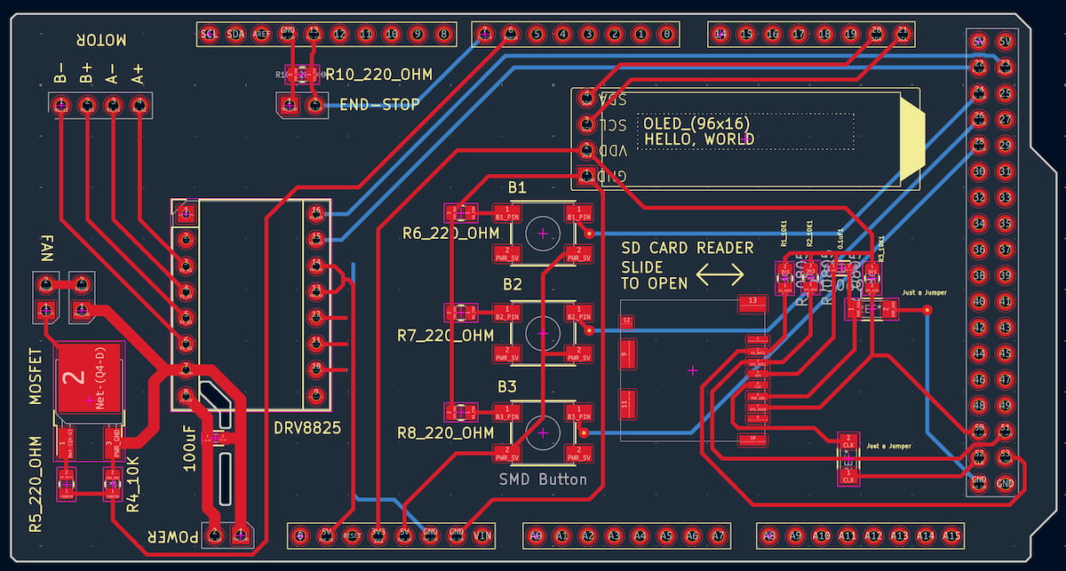
Version 0.3 includes:
| Pin | Net* |
|---|---|
| 6 | FAN |
| 7 | E-STOP |
| 20 | OLED_SDA |
| 21 | OLED_SCL |
| 22 | M1_STEP |
| 23 | M1_DIR |
| 24 | Button 1 |
| 26 | Button 2 |
| 28 | Button 3 |
| 50 | SPI_MISO |
| 51 | SPI_MOSI |
| 52 | SPI_SCK |
| 53 | SD_CS |
Milled FR1 2-sided copper on the Bantam Mill.
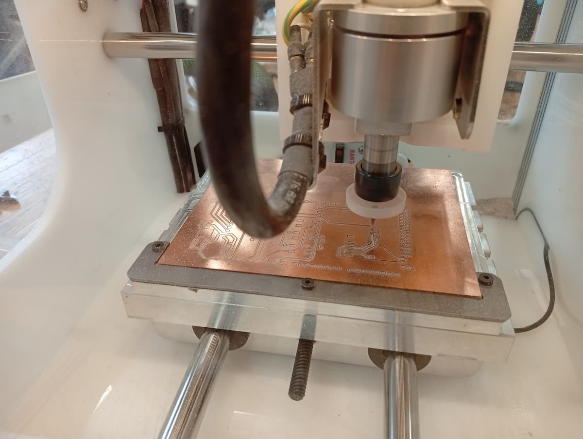
- Worked well: 2-sided board ended up to be accurate (within 0.5mm).
- Issue 1, Vias defaulted to 0.3, and so were not drilled
- Issue 2, Drill holes were not deep enough, to do with fixture, zero-ing or board warping. Because the flipping worked well, I could run the drill path from the second side. There is an offset that can be set in X, Y, and Z.
- Issue 3,Drill holes were not wide enough for some pins. Resized for recut.
- Issue 4, clearance for tall Arduino components (barrel jack and USB connector).
Next:
- Recut.
- I fixed Issue 4 while cutting, but, decided to change to the updated board outline, even though the edges destroy the circuit for the mosfet/fan, and some of the tracks for the motor connectors!
- Location of USB connector was accurate, but need to isolate from metal of connector.
- Location of powerjack on this board was off, and power jack was not perpendicular.
- copper is an expensive way to test your locations!
- …And it was kind of a non-issue. The hilt of the male pins raises it almost enough, and a bit of electrical tape on top, means you shouldn’t have to allow for it in the outline.
- Plan flips and toolchanges to save time. (Engraving Top > Engraving Bottom > Holes > Outlines)
- Test board with Multi-meter.
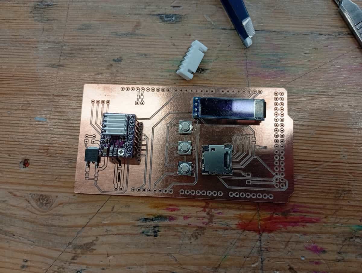
- Solder components. (SD Card Reader, the buttons, all resistors and capacitors are SMD; connectors and OLED have pins)
- Version 0.4 will use a daughter board to mount (2 or 3) DRV8825’s on it.