Week 3
Assignment - Computer-Controlled Cutting
- Group assignment:
- Do your lab’s safety training
- Characterize your lasercutter’s focus, power, speed, rate, kerf, joint clearance and types.
-
Document your work to the group work page and reflect on your individual page what you learned.
-
Individual assignment:
- Design, lasercut, and document a parametric construction kit, accounting for the lasercutter kerf.
- Cut something on the vinyl cutter.
From Assignment Details.
Group Assignment:
Laser Safety Training
-
[x] Did the laser introduction with my instructors.
-
Notice: Fire Point and Assembly Point notice
- Notice: Controls, End Stops
- Make Sure Extractor/Filter is working, and the duct gate is open
- PPE: Safety Glasses (not required for normal use)
- Never: PVC/Chlorine!
In case of Emergency:
- Fire Blanket
- Extinguisher
- Raise alarm
- Exit calmly to assembly point
Standard operation:
Epilog
- Starting up,
- Turn on the computer.
- Turn on the Epilog and the extractor(s). (On the Zing machine, open the duct gate also).
- Place your material flat within the hard rulers,
- Focus, with the spring depth gage, and the up and down buttons on the top surface of your material.
- Preparing and sending your file,
- Open Inkscape, and open your
SVGorDXFfile, File>PrintorCtrl+Pto send to the Epilog Dashboard program.
- Open Inkscape, and open your
- In the Epilog software,
- Assign your cut strategies and material settings.
- You can use the preconfigured materials, and make tweaks for the specific mateial you are using.
- Position your job (with cameras, in case of Epilog Fusion Pro).
- Print and select Run on the machine screen.
Trotec
- Turning on the machine (usually for staff):
- Turn on the computer, Open Trotec Ruby in Edge.
- Log in
- Import,
- Import your file.
AI,SVG,DXF, and image formats. - Check scale (in particular if DXF), position and set up colours for vectors and raster layers.
- Defaults are Black for Raster Engrave, Red for Vector Engrave, and Magenta for Cut. But it’s really easy to reassign them. Just make sure your graphics are recognised colours (RGB spectrum).
- Click
Create Job.
- Import your file.
- On the Prepare page,
- Select material
- Adjust material power and speed by clicking on the settings. Click on the coloured square to reassign.
- Position job(s) on the bed,
- Drag and align to material area. Use the red dot, updates on screen live to check the positioning relative to your material.
- Click
Send to Laser
- Prepare the machine,
- Extraction is switch on automatically, and runs for 2 mins after the job is complete.
- Load material flat on bed
- Set your focus (auto-focus or manual gage)
- Press the
Playbutton to send from Ruby to laser - Afterwards,
- Wait for extraction to clear fumes
- Remove parts carefully
- Clean edges / bed if required
Checklist and agreement:
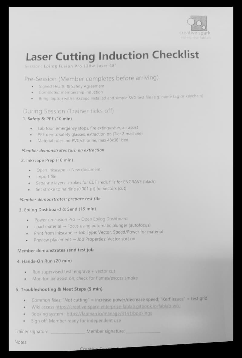
Laser Cutter Characterisation
Creative Spark has a Beambox, an Epilog Zing, an Epilog Fusion Pro, and an xTools F2 Ultra.
Fab Lab Limerick has a Trotec Speedy400, and an old Lasersaur.
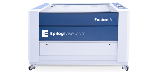
Epilog Fusion Pro
- Focus:
2.0"Lens - Power:
120W. - Work Area: 1219 x 914 mm
- Speed: up to 4.2 m/s
- Rate: Pulse configured through the Epilog Dashboard material settings, depending on the material
- Kerf/Joint Clearance: To be characterised.
- Type: CO2.
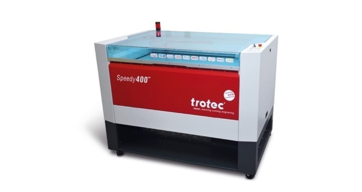
Trotec Speedy 400
- Focus:
2.0"Lens - Power:
80W, …however this is an older machine and recent maintenance measured a power drop of>10Wbetween source and cutting position. - Work Area: 1000 x 610 mm
- Speed: Original Specs for the machine state Max. processing speed: 4.32 m/s. The software presents each material speed as a
%of this value. - Rate: The software uses
1-60 kHz, depending on the settings for that particular material. Timber and Card are at the lower end, and plastics like Acrylic seem to be at the higher end. - Kerf: 0.4mm (see below)
- Joint Clearance:
0.2mm(see below) - Type: CO2 CeramiCore® laser source produced by Iradion GmbH
Kerf Test
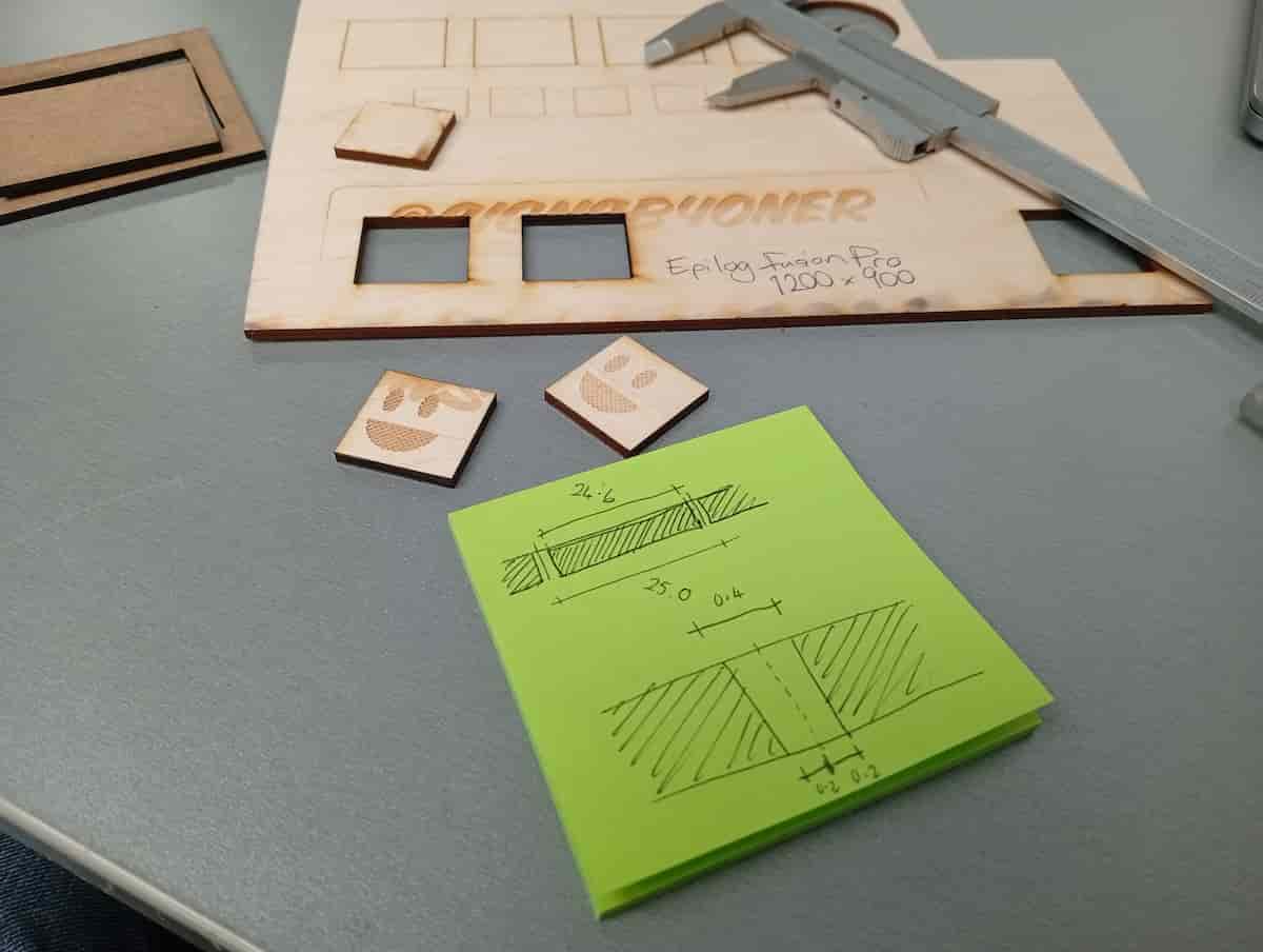
Steps
- Measure material thickness with a callipers (note that it could vary from the nominal thickness and that it could vary across the material!)
- Cut a square of a known dimension. Use a calipers to measure the inside of the hole, and the outside of the positive part
- And then you can calculate, $$ kerf = \frac{s_{inner} - s_{outer}}{2} $$
- To be sure, based on the measured thickness, make an array of slots, that vary (negative and positive). For a timber/timber product, a series of thicknesses ±0.2mm is a good guess.
- Cut both parts, and mark which is which(!)
- Try it out for the desired tightness.
Material 1.: MDF, 2.5mm (adapted for Trotec bulb)
- 100% power
- 0.6% speed
- 2 passes
- 1000 Hz
- 10 Power Correction
- 0mm Z-Offset
- Air-Assist On
- Source CO2
Material 2: Plywood, 3mm (adapted for Trotec bulb)
- 100% power
- 0.9% speed
- 2 passes
- 5000 Hz
- 10 Power Correction
- 0mm Z-Offset
- Air-Assist On
- Source CO2
Measured: 24.6mm (meant to be 25.0mm) So Kerf = 0.4mm, and Joint clearance = 0.2mm
Material 3: Acrylic, 3mm
- 100% power
- 0.2% speed
- 1 pass
- 6000 Hz
- 10 Power Correction
- 0mm Z-Offset
- Air-Assist On
- Source CO2
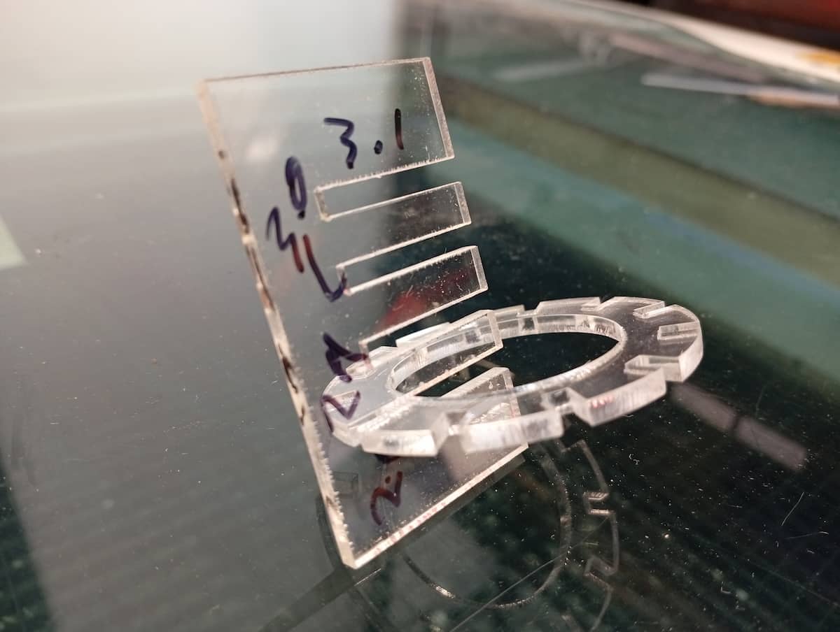
Tested best fit, “2.7mm”, so kerf is 0.15mm (each side)
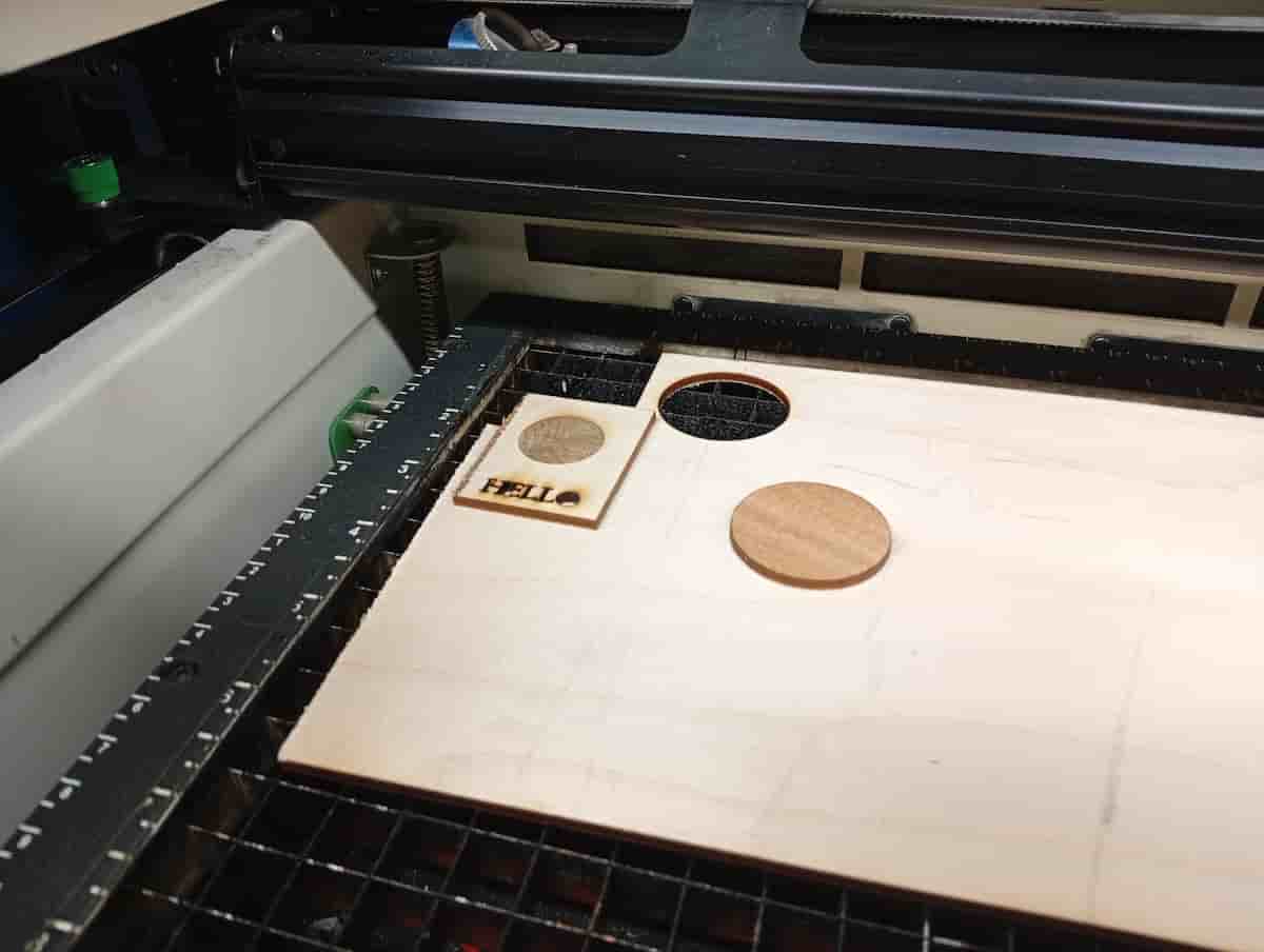
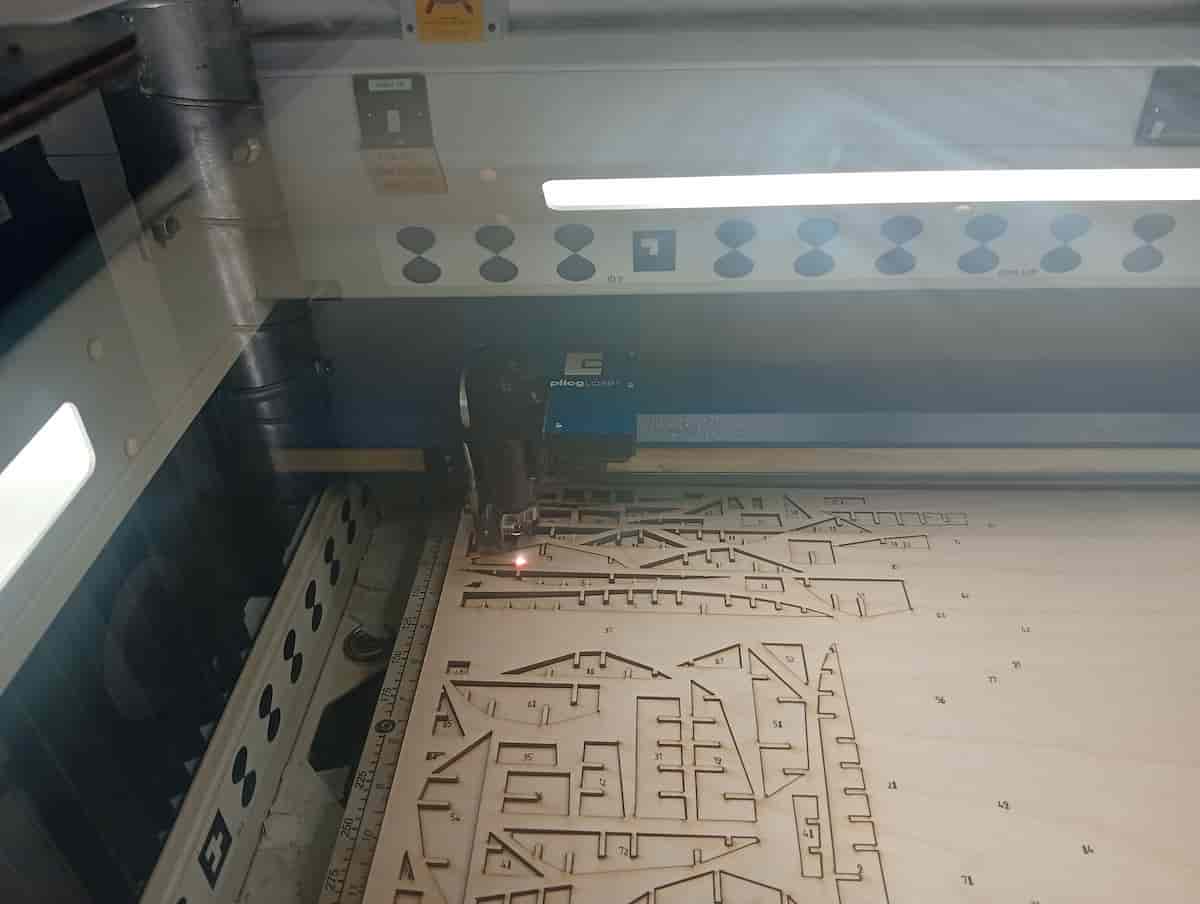
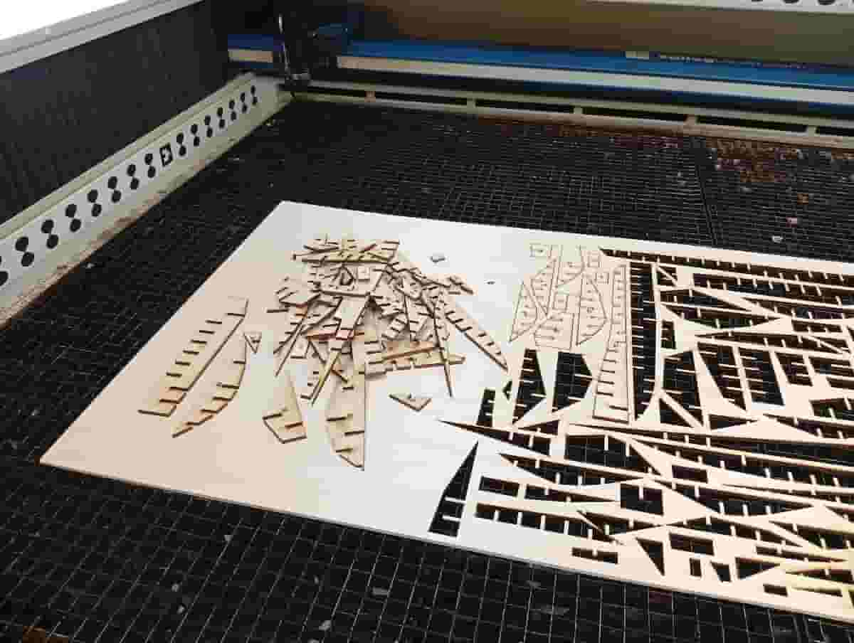
1st Laser Cut
The first step was to get familiar with the Epilog. In this case I used the Epilog Flux, and a 3mm Plywood offcut.
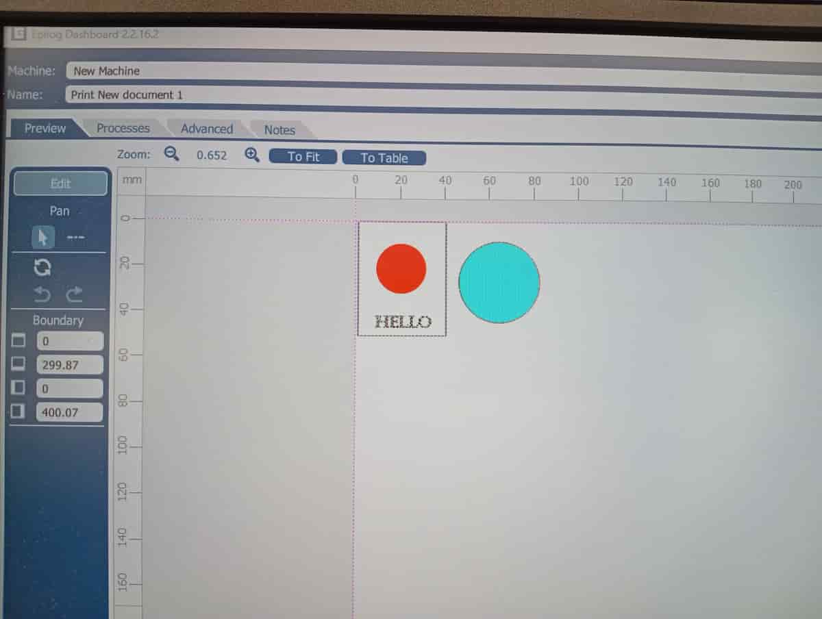
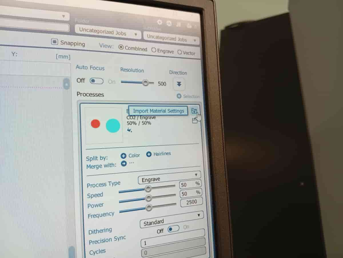
The drawing was in Inkscape. The Epilog software understands fills and hairline vectors. You can, additionally, add more to the list on the right. Have them filtered by colour, or type to set up different operations, with different speed and power settings. The open folder icon allows you select a material from the existing library. (Note as you do this may overwrite tweaks you made up to this point, and job-level settings, like resolution).
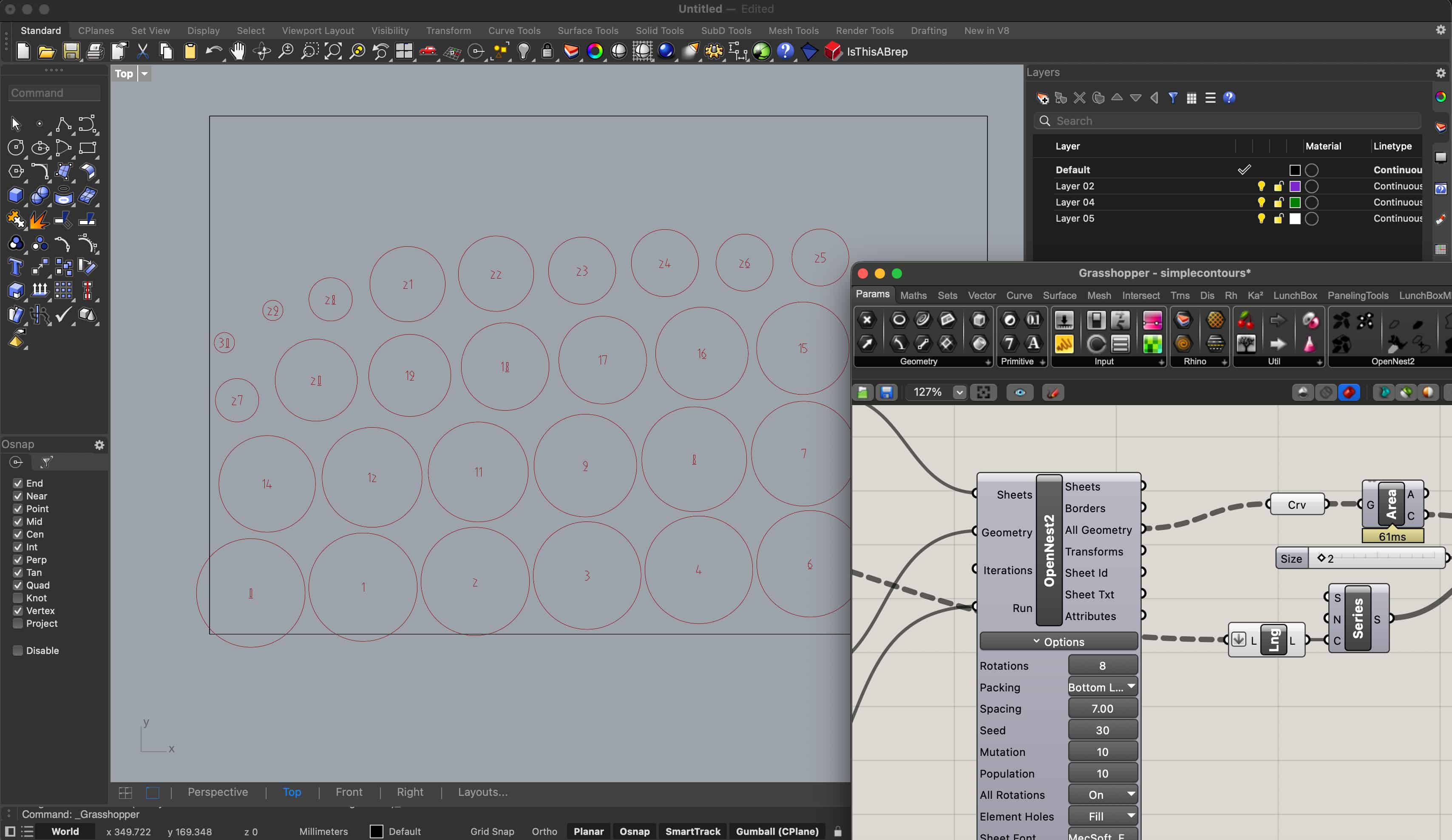
Grasshopper Parametric Script, pt 1.
Then, I experimented with a Grasshopper Script to slice a 3D object with an interlocking pattern. It uses the Contour node and the Region Slits node to do this efficiently. And I will apply OpenNest to lay out a cut sheet.
Grasshopper is a node-based, low-code parametric program that works with/within Rhino. ‘Flows’ work from left to right, and data passes along wires between nodes. Often the biggest challenge is managing data and lists of data.
Nodes allow you to use data from inputs, collections of data, series and psuedo-randomised data, and apply in a parametric CAD environment. Script nodes allow even further customisation in Python or C# or Net Basic.
Plugins like Kangaroo, Human, Lunchbox, Wasp, and Ladybug are popular, and available with downloads and discussion forum, on food4rhino.
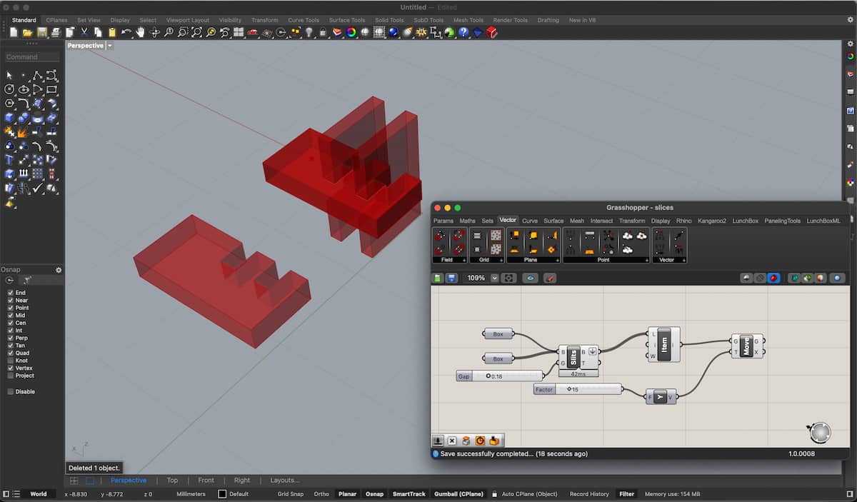
This is the most basic version of the Box Split node.
From the ribbon menu, go to Intersections > Shape > Box Slits.
- Box (thin line) is the horizontal box.
- Box (with the ticker line) are the two verticals.
- Input (“G”) of 0.18, which is the
Gap, i.e., 0.18mm (clearance for kerf, 0.09mm either side). - The output
Brep(“B”) goes to theList Indexnode, so I can show one result, moved +15 in Y.
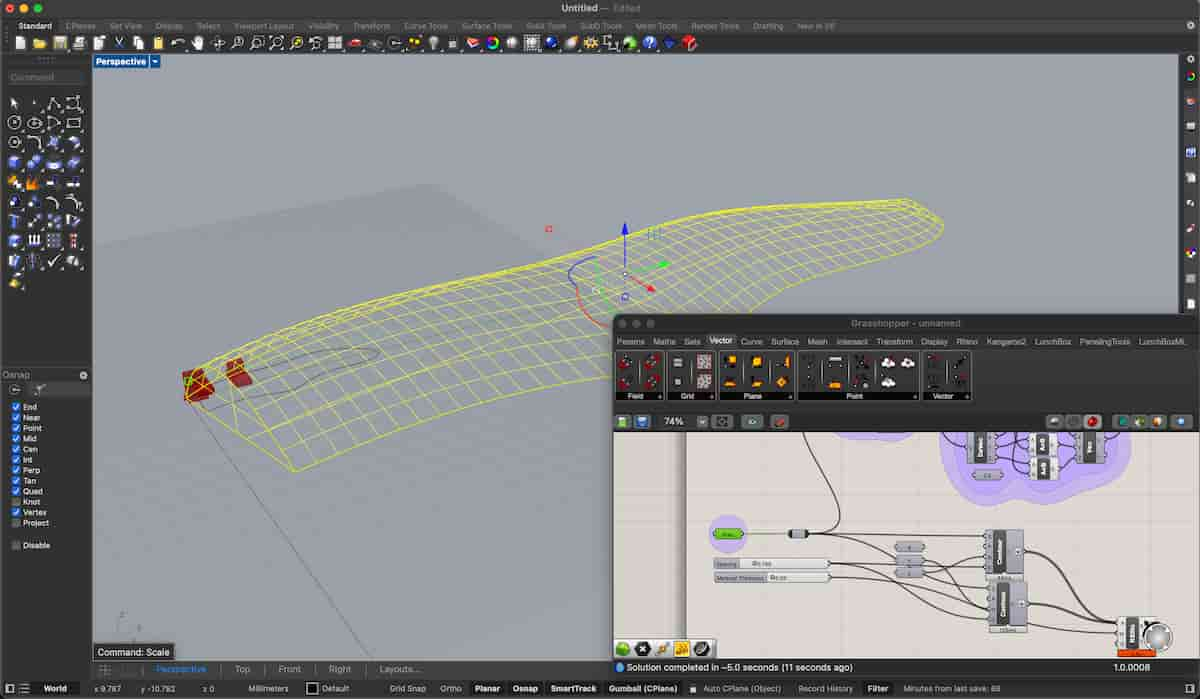
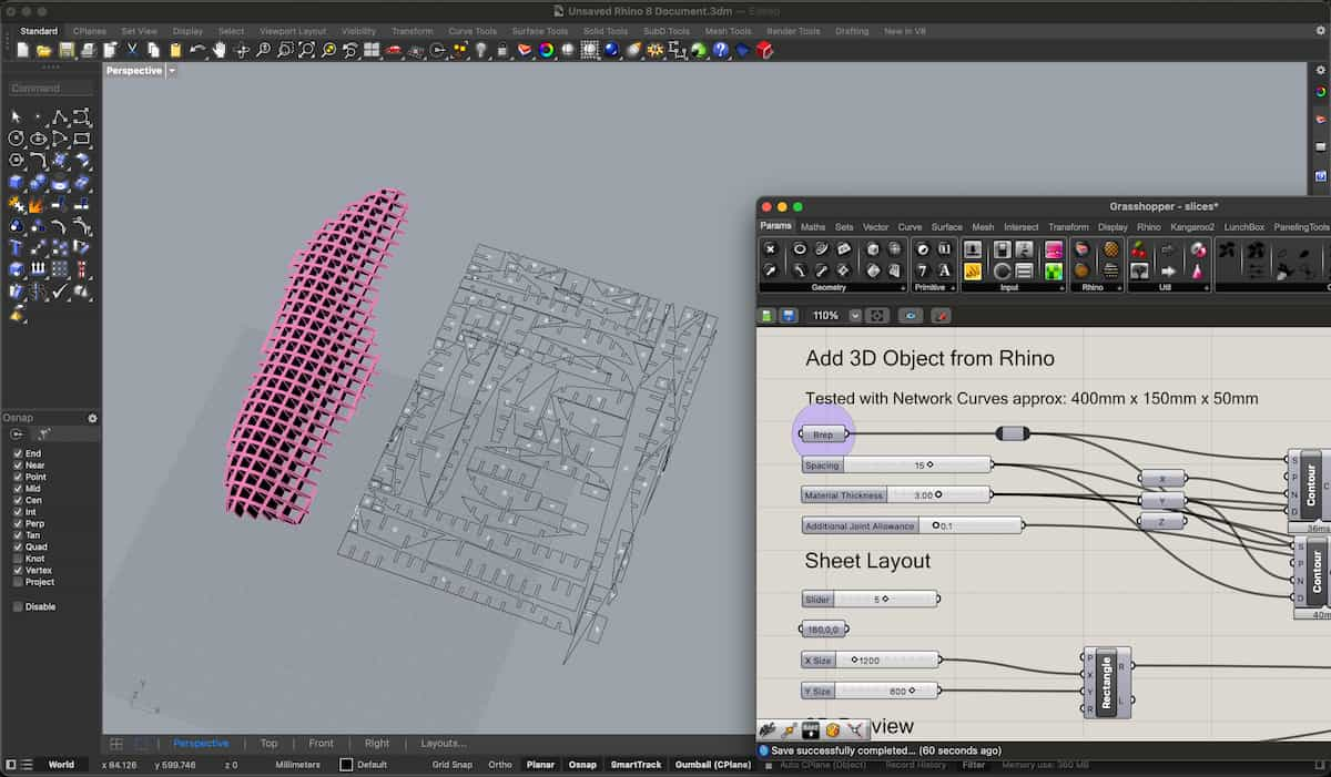
However, this version uses the Contour node as mentioned above. Allowing me to seperately deal with the X and Y slits.
OpenNest, then takes the combined list, and fits it to a rectangular shape provided, as best as it can nest. OpenNest’s second output is a transformation, or list of transformations (vector + rotation + scale) that transforms a list of text objects to end up in the same place relatively without having to recalculate!
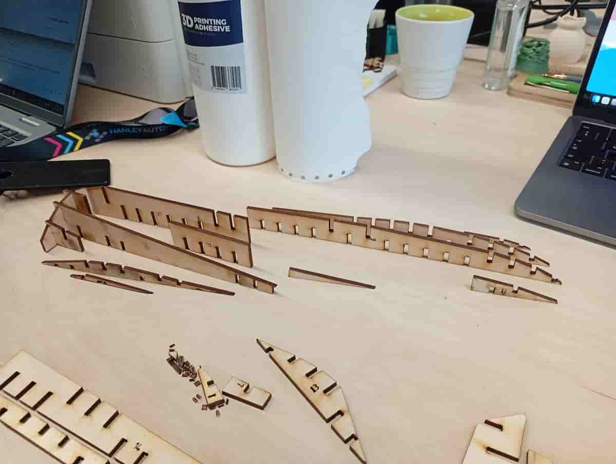
Grasshopper Conclusion
I wanted to experiment with grasshopper for this assignment. The limits I found were:
- Could not adjust the slot depth (always 50/50)
- Could not add notches at opening, or taper, or added clip features.
RegionSlitscomponent produced some self-intersecting boundaries.RegionSlitsmissed some intersections entirely.- The assembled model was not assemble-able, numbers not in order and direction of slots not consistent.
Grasshopper Contd.
I used the Contour node to make a stacked model, based on a BREP (ie a NURBS rhino shape, or a polysurface).
OpenNest 2 is the plugin I used to nest the slices. It’s a little buggy sometimes, and I find it’s best to disconnect, and reconnect the nodes. There are examples on food4rhino.
File:
Cut something on the Vinyl Cutter
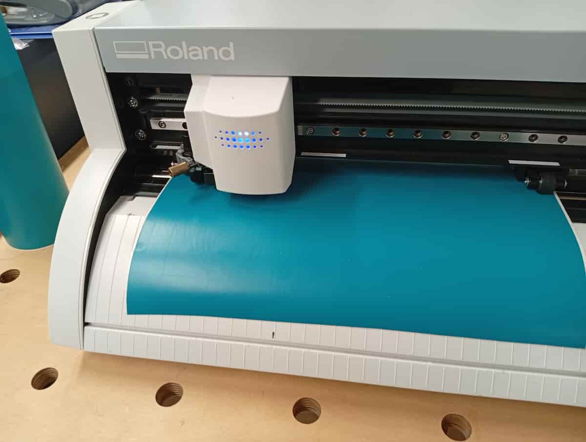
To make use of the Vinyl Cutter, I drew something in Inkscape. The Vinyl Cutter is a Roland GS2-24, and I used a laptop in the lab with the Roland DGA Print Driver.
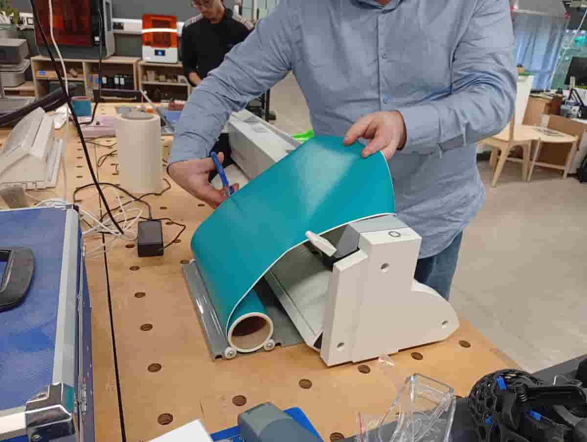
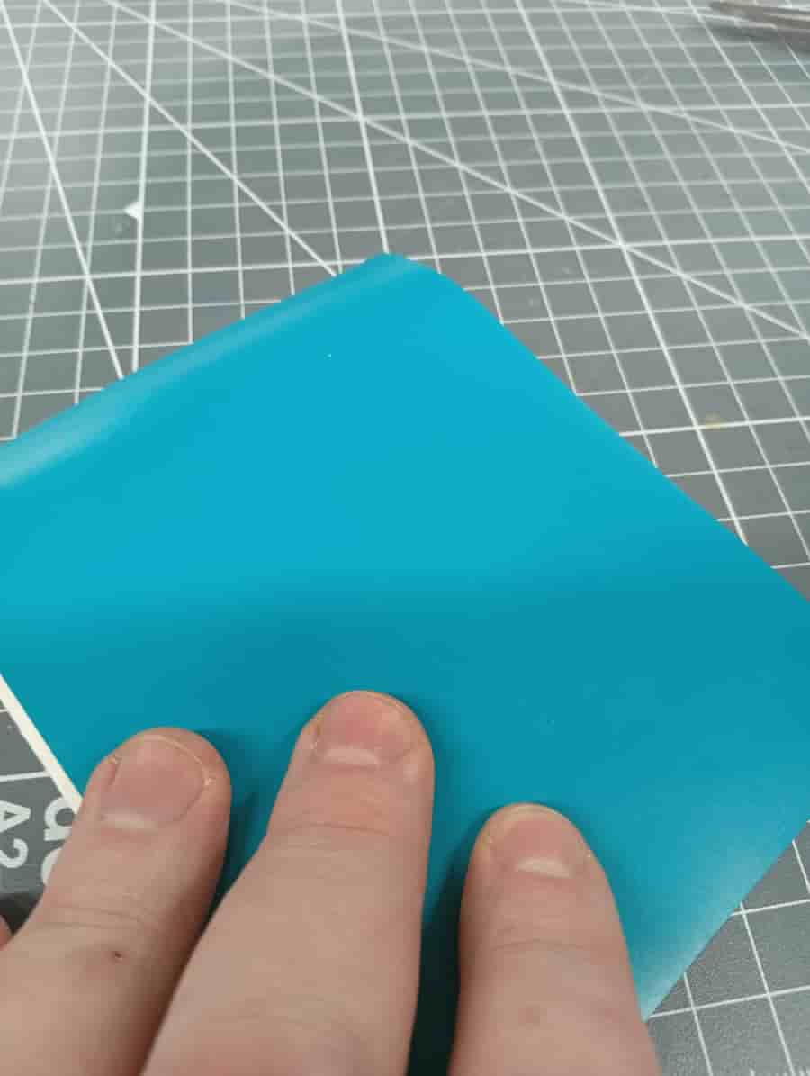
From the roll, cut roughly to length. This is a 300mm roll of polymeric adhesive vinyl.
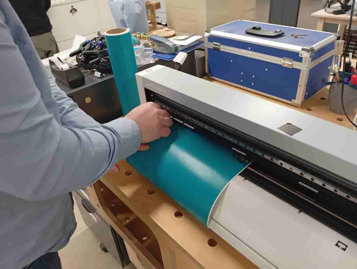
Release the lever at the back left of the machine. Feed the vinyl through the machine from the front. Adjust the wheels. The white stickers correspond to the knurled parts of the bar underneath, so make sure both wheels are within the white demarkated sections. Make sure the edge is parallel with the lines marked on the machine, so that it doesn’t misalign itself too much as it moves.
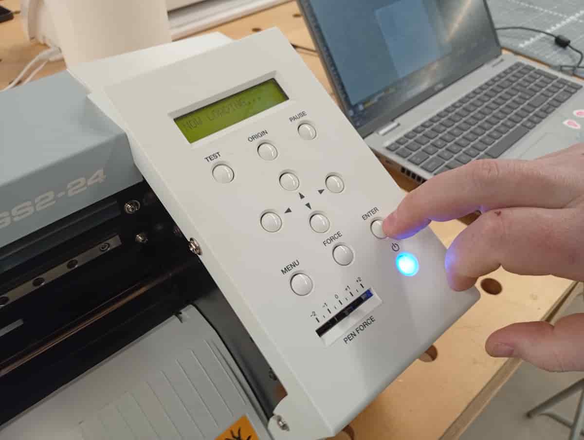
From the menu, select “Piece” to add.
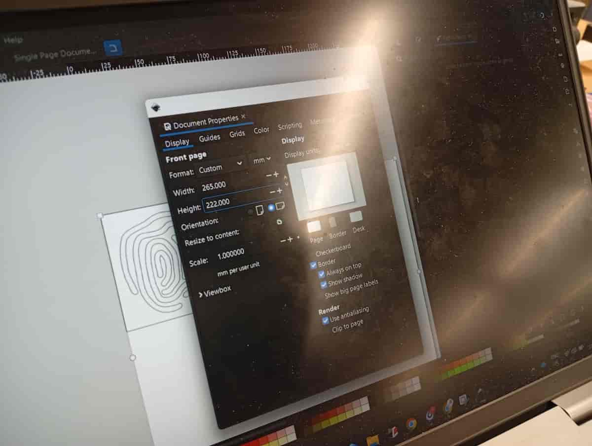
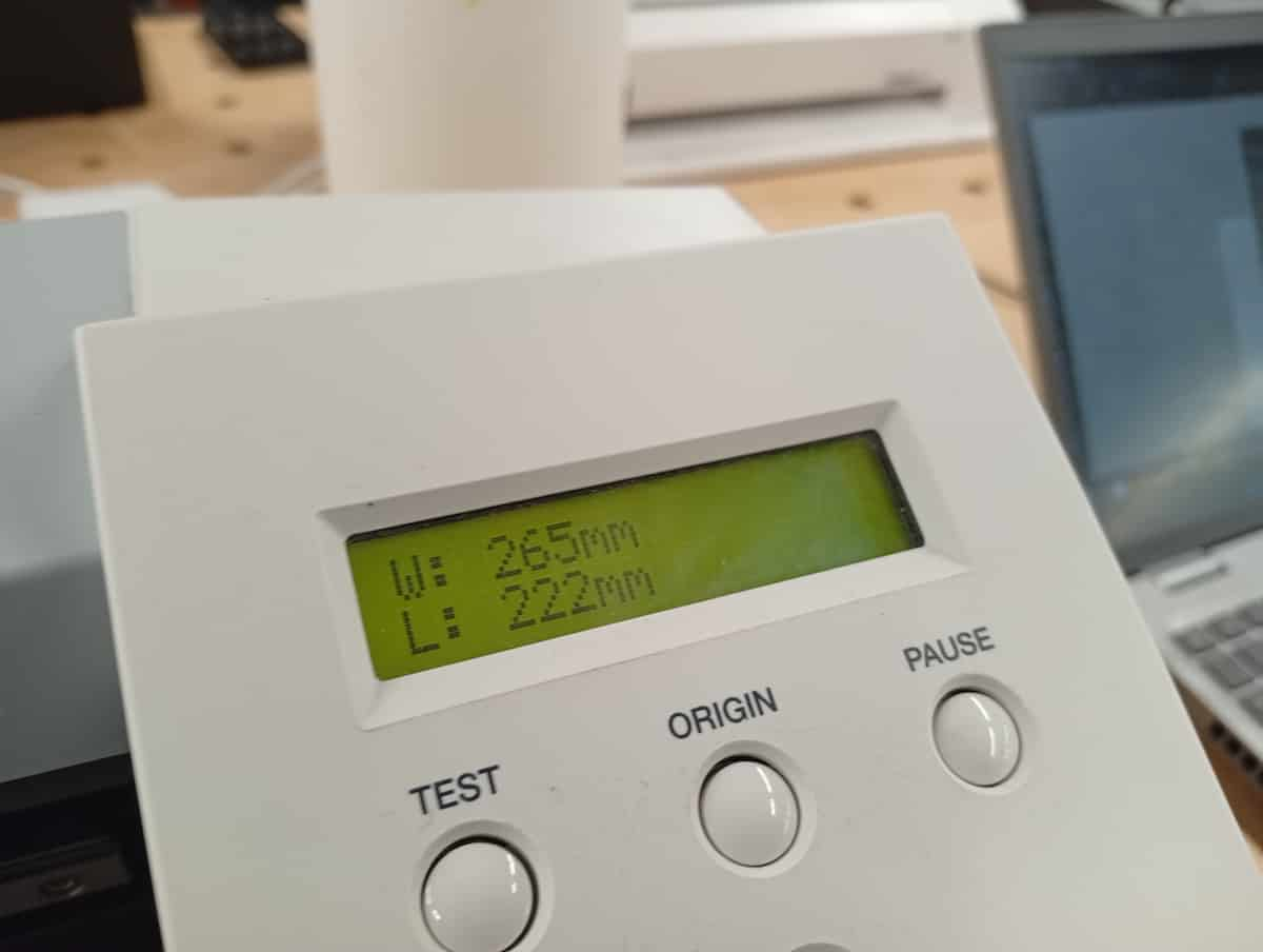
The carraige travels the width of the machine, and rolls the piece through. It returns the width and height on the display. Update this in Inkscape (Document Preferences).
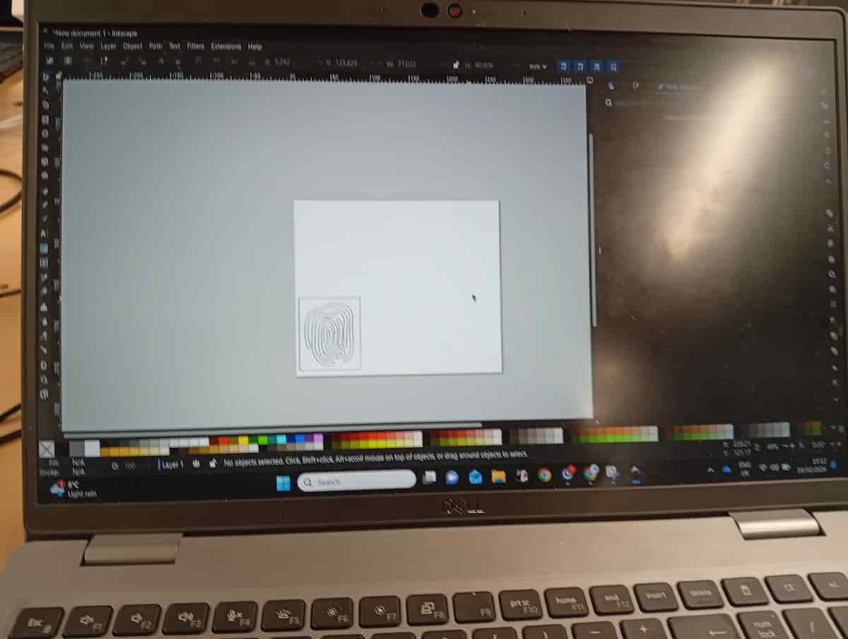
Put your drawing in place according to the updated page size.
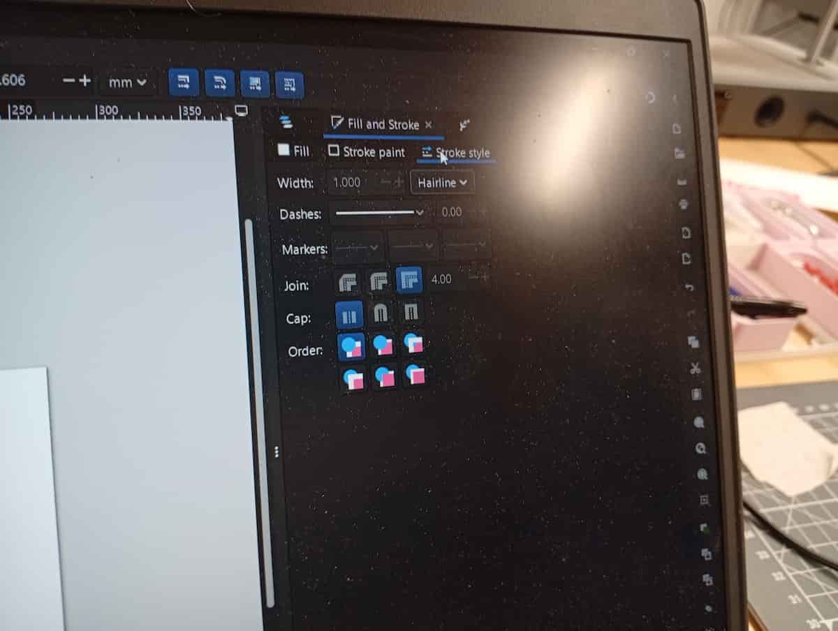
Set Stroke Width to “Hairline”, and Style to Solid, Opaque, Black.
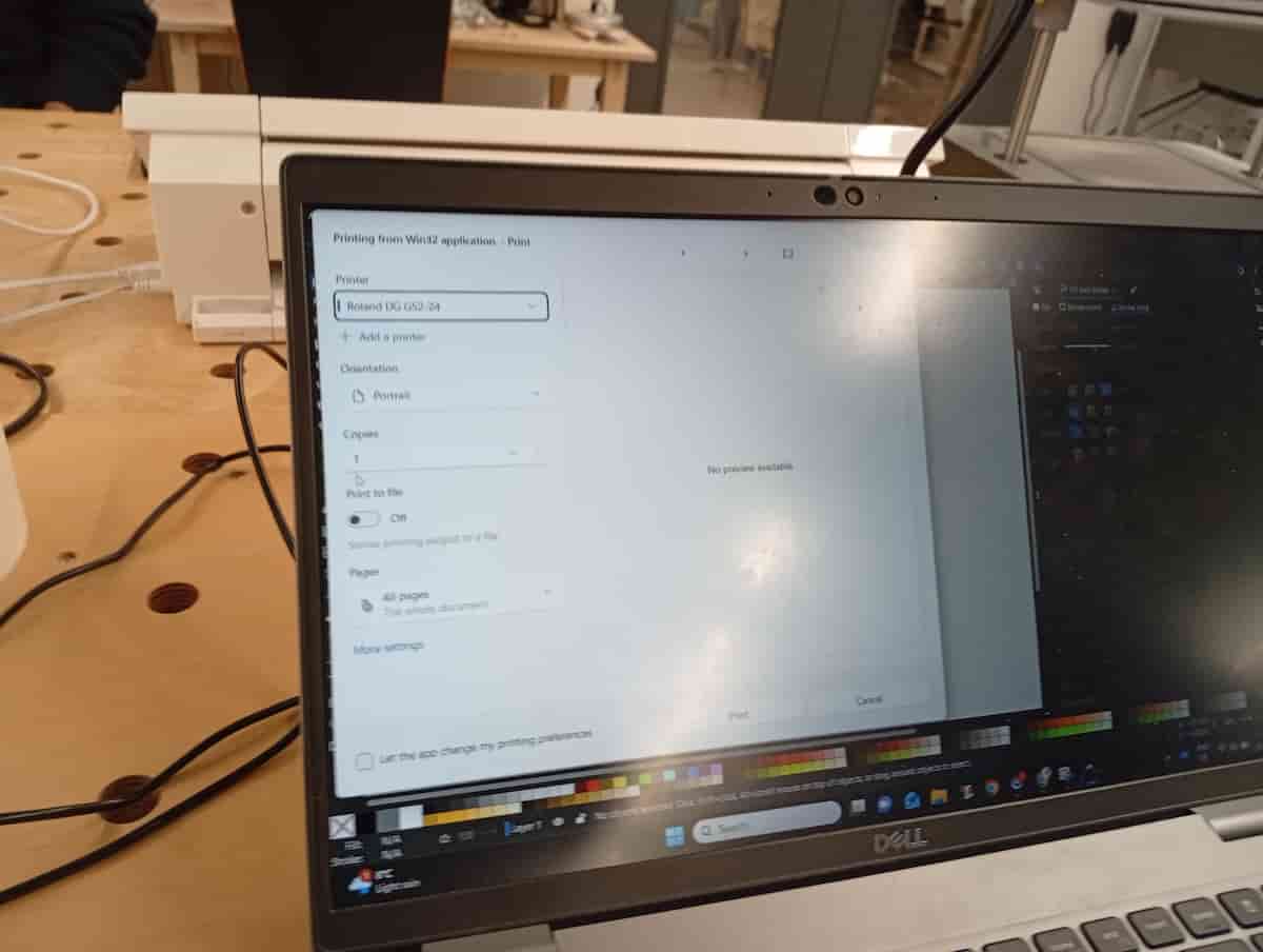
File and Print. Choose Roland GS2-24.
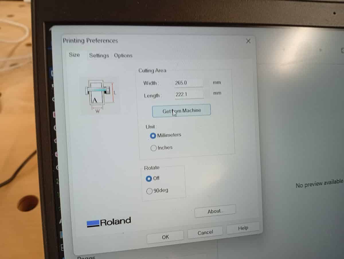
Choose Advanced and Get From Machine to import the same dimensions to the print driver automatically.
Observe cutting.
Remove work when done.
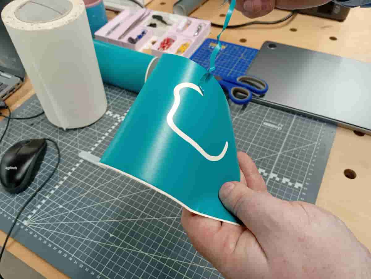
Weeding. Depending on what you are keeping, this step may vary. Use tweasers and scalpel to weed out the various cut parts.
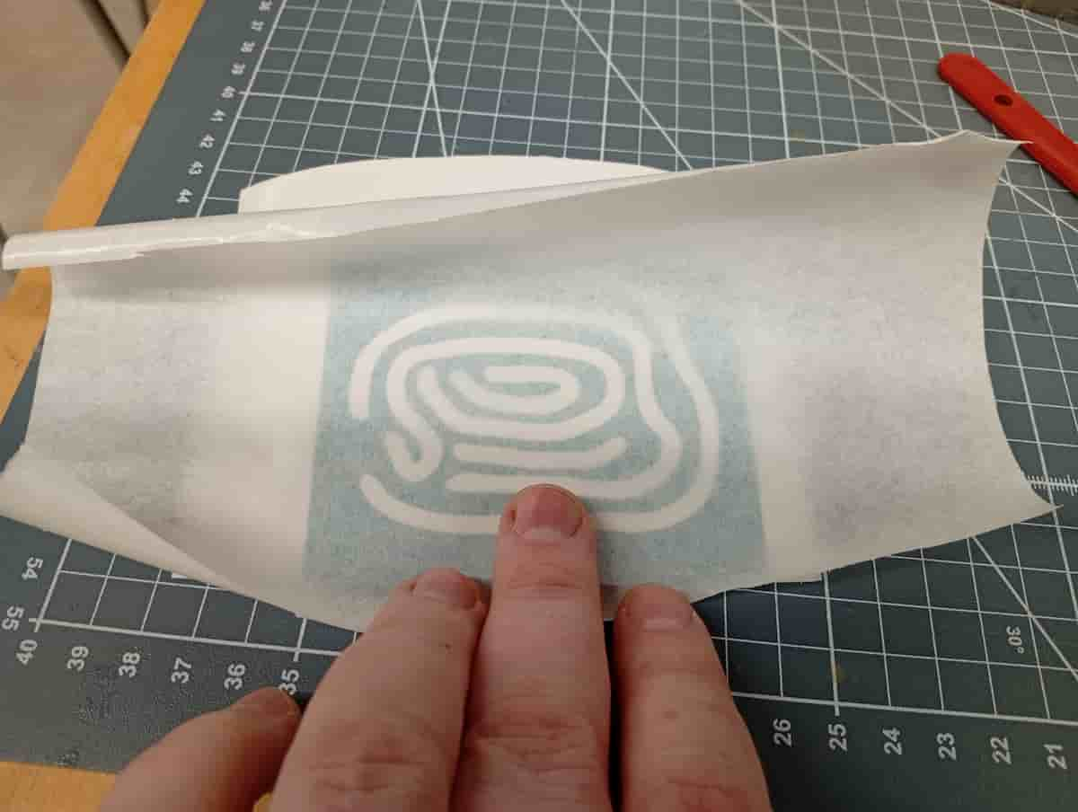
Transfer Tape.
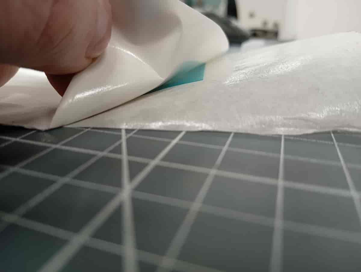
Remove the paper backing. Pulling at a low angle to avoid pulling parts off the transfer tape.
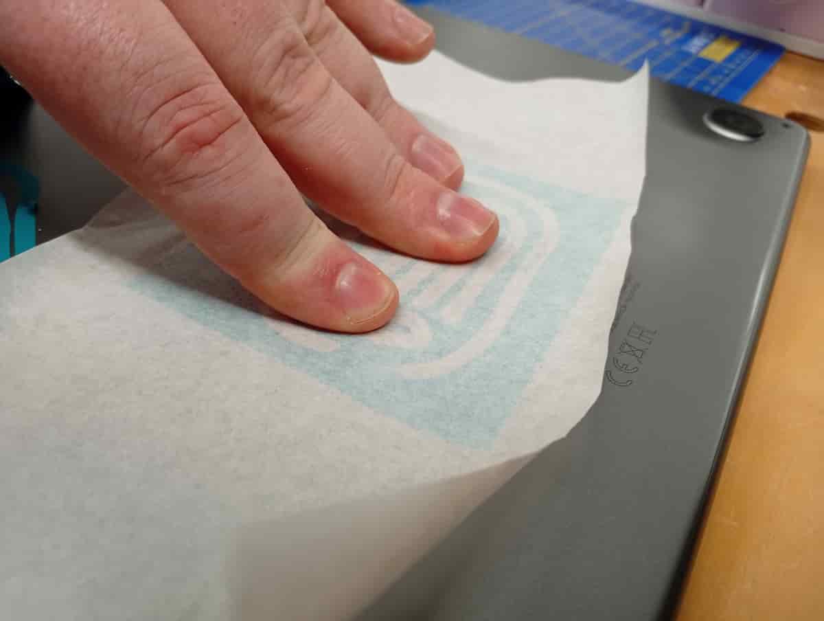
Apply to the centre and press from the centre out.
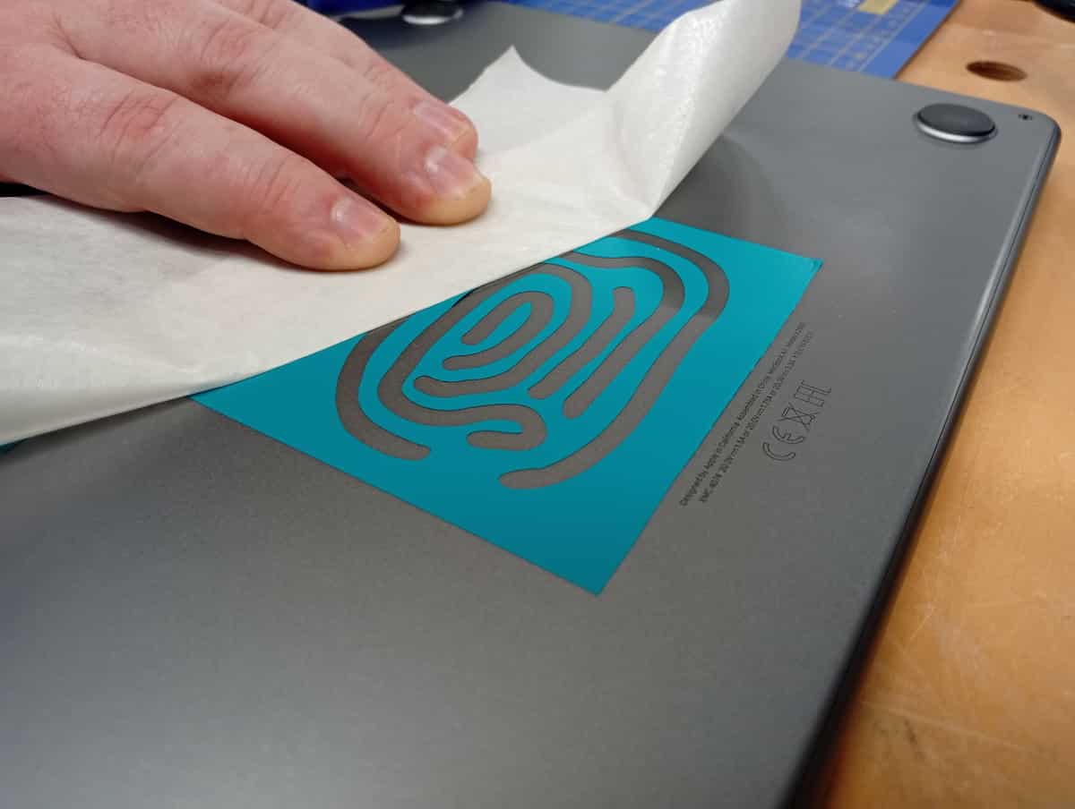
Now with the transfer tape, remove this from the sticker without disturbing the sticker.
 Et voila!
Files
- All, ZIP
- fingerprint.svg (11KB)
- Slices(GHX)
- test.dxf (525KB)
- simplecontours.ghx