Week 7 - Computer-Controlled Machining
This week, we began to formally engage with CNC Milling. CNC machining is the core link in the digital manufacturing project for realizing physical production - from CAD model design to CAM programming, and then to the actual cutting process on the machine tool, all of which rely on a mastery of the operating specifications, machining processes, and safety procedures of CNC milling machines.
Group assignment:
Understand the safety regulations and basic information of CNC milling machine processing from an overall perspective. For example, the basic parameters and characteristics of CNC milling machines, the content of operation security training, the machine pre-inspection process, environmental and material safety requirements, and the "safety rules" during the operation process. Through systematic learning and practice, establish a comprehensive understanding of CNC machining safety and machine tool basics, and build a solid safety defense line for subsequent actual machining operations.
Individual assignment:
Taking the CNC milling of a chair as the project objective, complete the full-process practice from design to finished product. First, assign individual tasks, then use OnShape to complete the CAD model design of the chair, including the structural design of the seat and legs, size adjustment and tolerance adaptation, as well as the structural optimization of tenon-and-mortise joints (T-bone/dog bone); then generate DXF cutting files and conduct process planning, use MasterCam X6 to generate the G-code required for machining, complete G-code conversion and machining simulation verification; subsequently, perform the actual machining operation of CNC milling, and finally complete the assembly and effect display of the finished product.
Overall, the focus of this week is not to complete high-precision complex machining projects, but to establish a basic understanding of the entire process of CNC milling, including how to comply with machining safety regulations, how to use CAD/CAM tools to complete the transformation from design to machining, and how to verify the feasibility of machining processes through simulation and actual operation. Through these basic exercises, a solid practical foundation will be laid for subsequent digital manufacturing and physical project development.
Group Assignment
Group Assignment Page: https://fabacademy.org/2026/labs/chaihuo/docs/week7/week7_group_assignment
2. Security Training
Before operating the CNC machine formally, we first conducted Security Training. The spindle speed of the CNC milling machine is high, the cutting force is large, and the processing object is also large-sized sheets, so it is different from desktop-level equipment and cannot rely solely on experience for operation. During the training, I focused on recording the following points:
- When operating, do not wear loose clothing or gloves that are easily caught, and long hair must be tied up. When the spindle and cutting tools are rotating at high speed, any hanging objects are at risk of being caught.
- Before starting the machine, it is necessary to confirm the position of the emergency stop button. Both the operator and the assisting students nearby should know how to immediately stop the machine in case of an abnormality.
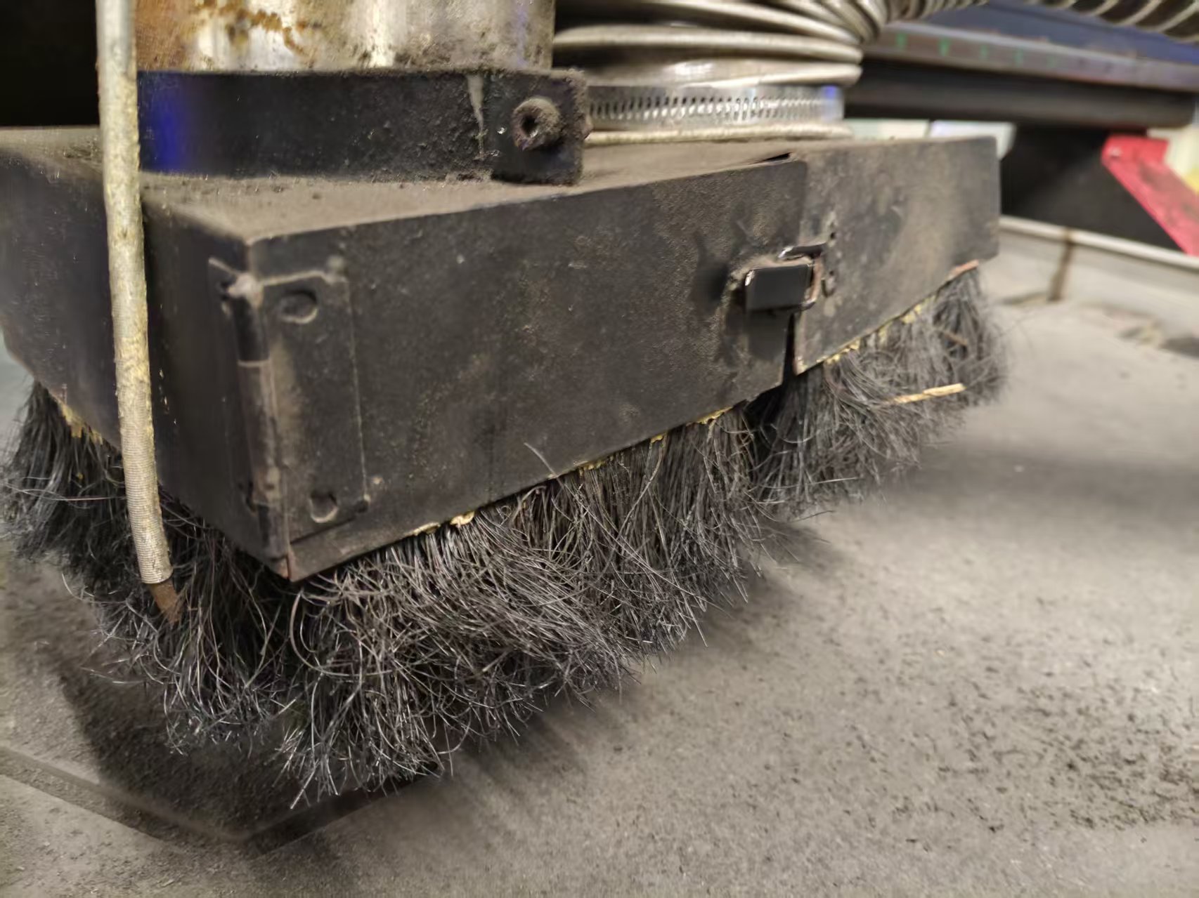
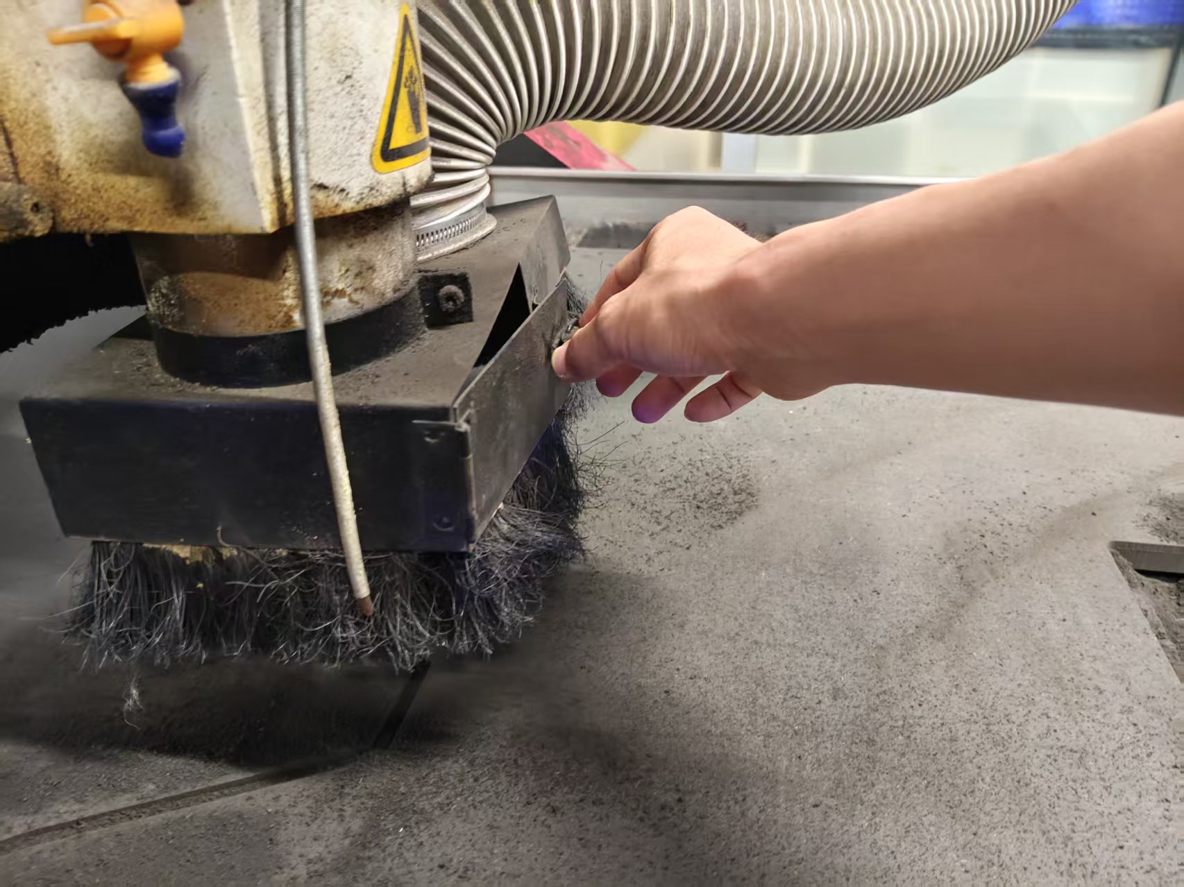
- Before processing, it is necessary to check the cutting tools, fixtures, plate fixation, and dust removal system. Loose cutting tools, unsecured plates, or insufficient dust collection can all affect the processing quality and may also pose a danger.
- Do not put your hands into the processing area or reach across the motion range to pick up items while the machine is running. Even if the program is paused, the spindle will not stop instantly.
- When processing MDF/HDF, a large amount of dust will be generated, so dust removal equipment needs to be turned on, and masks and goggles should be worn. When processing for a long time, attention should also be paid to noise protection.
- Before starting the program, perform a dry run or simulation check first to confirm that there are no obvious issues with the path, origin, and tool height, and then proceed with formal cutting.
These rules may seem basic, but when standing next to an actual machine tool, it becomes evident that the risks feel more real. The first step in CNC machining is not to turn on the software, but to confirm that people, machines, materials, and the environment are all in a controllable state.
1. CNC Milling Machine Information
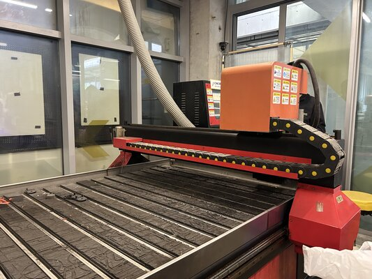
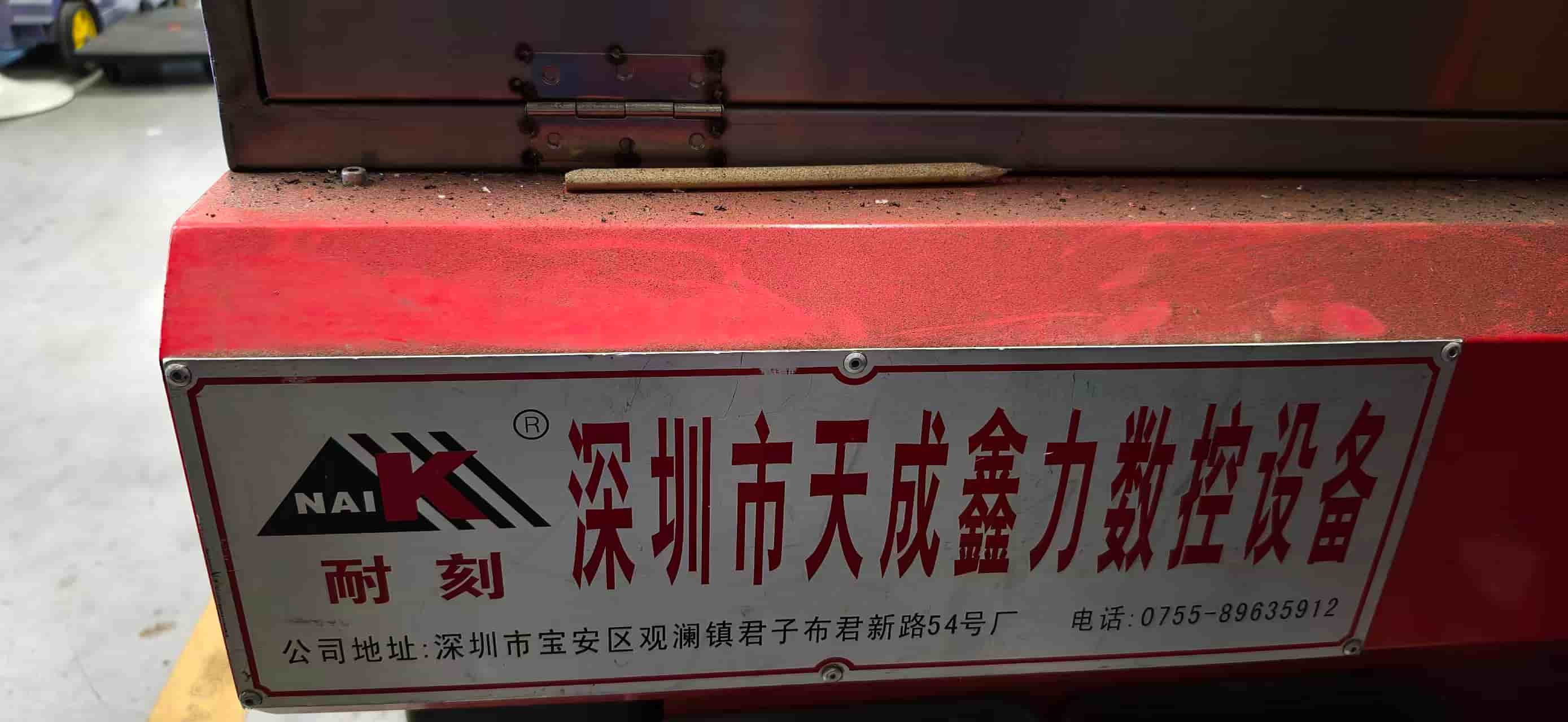
The CNC milling machine used in our laboratory is Tiancheng Xinli 3STX-1325A. Since the same laboratory equipment is used in this course, the CAM settings, tool paths, and machining parameters in subsequent individual assignments are all based on the capabilities of this machine.
| Project | Parameter |
|---|---|
| Manufacturer | Tiancheng Xinli CNC |
| Model | 3STX-1325A |
| Working Area X × Y | 1300 mm × 2500 mm |
| Z-axis travel | 180 mm |
| Spindle speed range | 0-24000 rpm |
| Spindle Power | 3 kW water-cooled spindle |
| Control File Format | G-code / UPP / NC |
| Maximum cutting feed rate | 15000 mm/min |
| Positioning accuracy | ±0.15 mm / 300 mm |
| Positioning accuracy | ±0.15mm/300mm |
3. Material Information
This week, 18 mm MDF/HDF boards were used for testing and personal processing. The nominal thickness of the boards cannot be directly used as a design basis because the plug-in structure is very sensitive to thickness. Therefore, we measured the actual thickness with a caliper before processing.
- Nominal thickness: 18 mm
- Actual measured thickness: 18.3 mm
- Sheet size: 1220 mm × 2440 mm
- Material characteristics: high density, heavy weight, and a large amount of dust during cutting
The actual thickness of 18.3 mm is very important for the subsequent design. If the slot width is still designed to be 18.0 mm, the parts may need to be forced in; if the slot width is too large, the chair will wobble after assembly. Therefore, the material measurement results from the group test directly influenced my personal chair design.
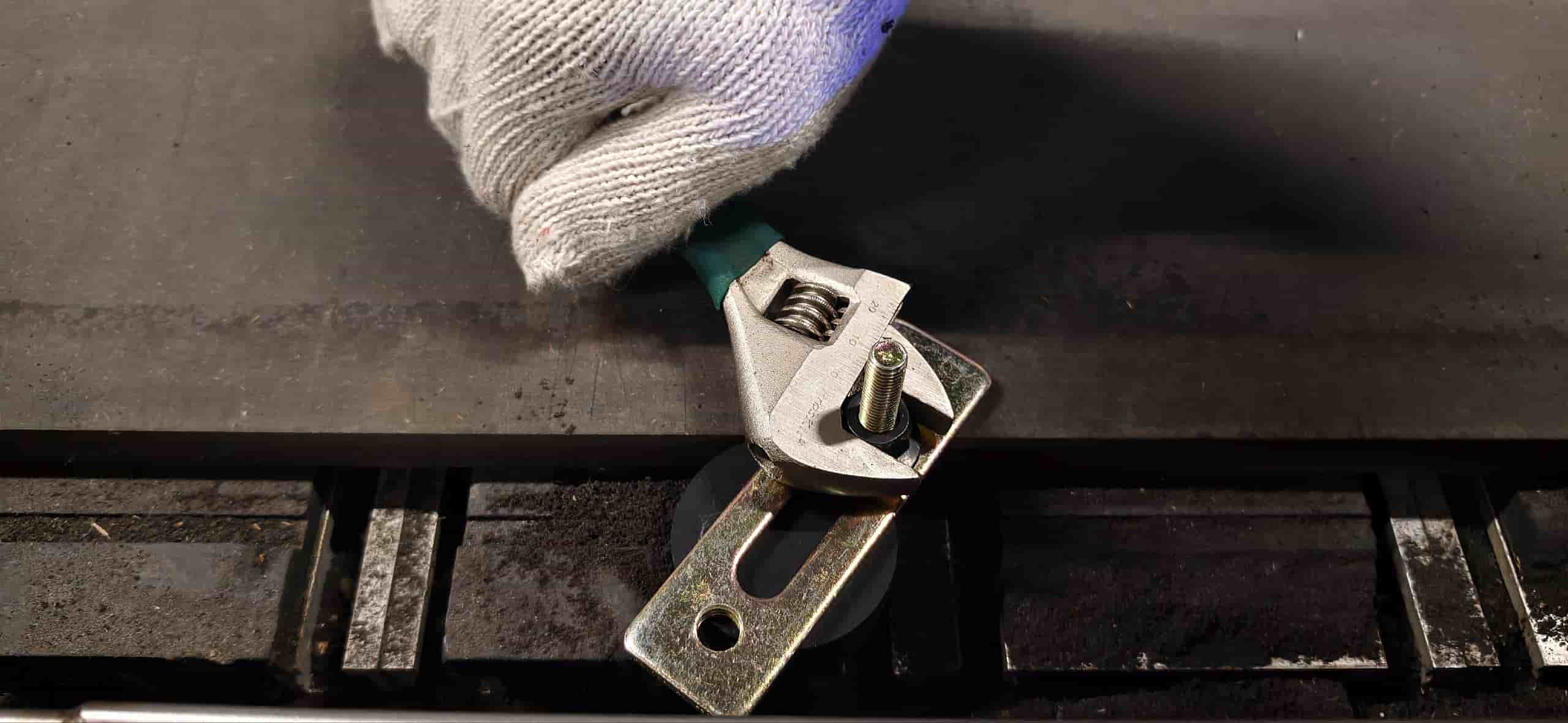
4. Machine Pre-inspection and Clamping
Before processing, we first clean the workbench surface and the sacrificial plate. Sawdust, debris, or protrusions on the workbench surface will prevent the board from fitting flatly, resulting in inconsistent cutting depths at different positions for the same program.
Next, lay the plate flat and secure it on the workbench. When securing, ensure that the pressure plate, screws, or clamps do not enter the tool path. Since the plate is large in size and heavy in weight, multiple people need to collaborate during handling and positioning, and it should not be forcefully moved by a single person.
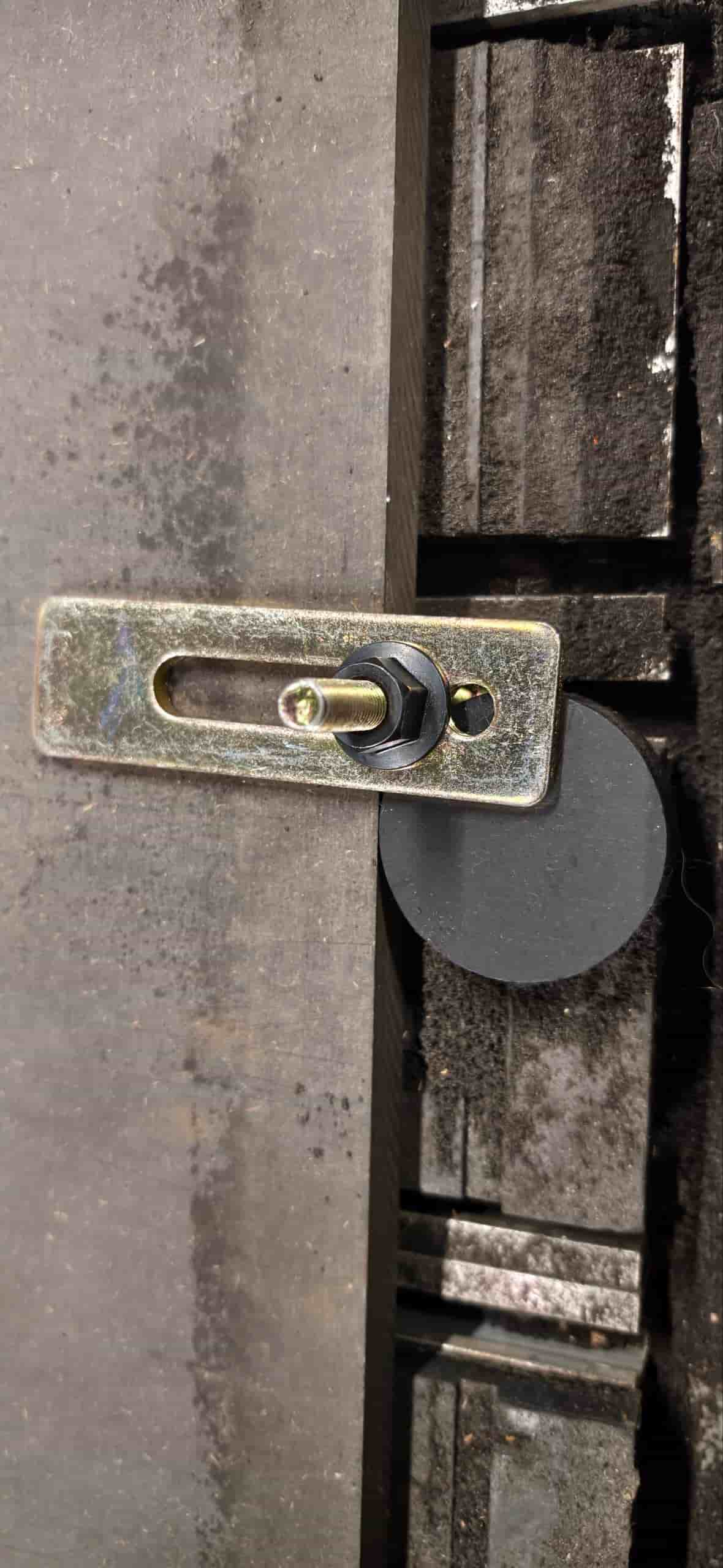
Set the workpiece origin after completing the clamping. The X/Y origin is set near the corner of the plate, and the Z origin is set on the upper surface of the plate. Special attention should be paid here: the cutting depth in this design is calculated relative to the plate surface, so the Z zero point should be based on the upper surface of the material, rather than the machine table.
5. CAM and Machining Sequence
The focus of the group test is to understand how the tool path affects actual cutting. For contour cutting and slot machining, we follow the sequence of "inside first, outside second; small first, large second".
First, machine the internal slots, holes, and pocket areas, then cut the outer contour. The reason is that once the outer contour is cut, the part may loosen from the whole sheet. If the internal structure is machined after the part has already loosened, both accuracy and safety will deteriorate. This principle is also applied by me to the machining of my personal chair: first cut the cross slot in the center of the seat surface and the middle slot of the chair legs, then cut the outer contour of each part.
6. Parameter Testing and Results
The goal of the group assignment is to observe the effects of spindle speed, feed rate, and single-pass depth of cut on cutting quality, and to find the machining range suitable for this machine tool, this material, and this cutting tool.
The test file includes three types of content:
- Contours and rectangular grooves of different sizes are used to observe edge quality;
- A slot with a known width, used to estimate the actual cutting width of the tool and machining deviation;
- Multiple sets of insertion slots with different gaps, used to determine the press-fit range of MDF boards.
During the testing process, we fixed the spindle speed and varied the feed rate and cutting depth. At lower feed rates, the tool stays in a local area for a longer time, making it prone to heat generation and slight discoloration at the edges; when the feed rate is too high, the cutting edge becomes rough, and burrs are more likely to appear on the exit side. When the single cutting depth is too large, the tool load increases significantly, so for plates around 18 mm, layer-by-layer cutting is more suitable.
This test also re-verified the internal angle issue: circular milling cutters cannot machine true 90-degree internal right angles. Without dogbone corners or T-bone reliefs, square tenons will be blocked by the rounded corners of the internal angles of the notches, preventing the parts from being fully inserted. This discovery directly influenced my personal design, and I added dogbone structures to the joining positions of the chair seat and chair legs.
7. Recommended processing parameters
Combining group testing and subsequent individual processing, the reference parameters used for MDF/HDF board processing this week are as follows:
| Project | Settings |
|---|---|
| Tool | 8 mm flat end mill |
| Spindle speed | 24000 rpm |
| Feed Rate | 5000 mm/min |
| Processing Method | Layered cutting, starting with the inner contour and then the outer contour |
| Z Zero Point | Upper surface of the plate |
| Design Considerations | Set the slot width based on the measured board thickness and add Dogbone / T-bone for the inner corner |
These parameters are not fixed formulas and only apply to this machine, this type of sheet material, and the current tool state this week. Before actual machining, judgment still needs to be made based on the material, tool wear, and cutting sound.
8. Group Assignment Summary
Through group assignments, I've understood that CNC machining cannot solely rely on software files. The lines in CAD are just the starting point of machining; what truly affects the results also includes the measured thickness of the material, tool diameter, plate fixation, cutting sequence, feed rate, and spindle speed. Especially for the plug-in structure, a tolerance change on the 0.1 mm level can turn a part from "not fitting in" to "too loose". These test results provided the parameter basis for my personal chair design.
Individual Assignment
1. Individual task assignment
My personal assignment is to design and fabricate a spliced MDF chair. The chair does not use screws or glue, but is assembled through the central slot of the seat, the tenons of the chair legs, and the cross slots between the two chair legs.
The focus of this assignment is to document the design process: I need to explain why this structure was chosen, how the dimensions were determined based on material thickness, how to address the issue that CNC circular cutters cannot machine internal right angles, and how to convert the model in OnShape into a DXF file that can generate tool paths in MasterCam.
2. Structural Design Concept
The initial direction I determined was to make a small chair assembled from sheet metal parts. CNC milling is suitable for machining two-dimensional profiles, and then forming a three-dimensional structure through plug-in connections. Therefore, I disassembled the chair into two main parts:
- Seat surface: Provides a sitting surface and has a cross-shaped slot at the center;
- Chair leg: Composed of two mutually intersecting support plates, the upper end is inserted into the slot of the chair seat, and the lower end contacts the ground to form support.
The advantage of this structure is that it has a small number of parts, clear assembly logic, and can also reflect the characteristics of "two-dimensional cutting to three-dimensional assembly" in CNC sheet metal processing.
3. OnShape Design Process
3.1 Establish the seat surface plan
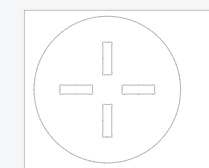
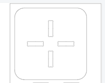
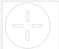
I first created a sketch of the seat surface in OnShape. The seat surface tried two types of contours: circular and square with rounded corners. The circular seat surface is visually softer, while the square seat surface with rounded corners is closer to the stress range of common stool surfaces and is also more convenient for layout.
A cross-shaped through slot is provided at the center of the chair seat to receive the tenon at the top of the chair leg. The slot position needs to be centered; otherwise, the stress will be biased to one side after the chair leg is assembled. The chair seat size is set to approximately 300 mm, which can serve as the basic support range for a small chair seat while not taking up too much board material.
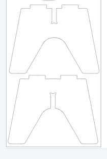
3.2 Establish Chair Leg Solution
The chair legs adopt a bilaterally symmetric structure. When drawing the sketch, I first draw the centerline, and then use symmetric constraints to establish the left and right side profiles, which ensures that the forces on both sides are consistent. The top of the chair leg retains a tenon for inserting into the center slot of the chair seat; the middle of the chair leg is slotted to allow the two chair legs to cross each other.
The height of the chair legs is set to approximately 250 mm. Since this is a small chair for course practice, I prioritize clear structure and controllable processing over making it the size of a full adult chair. The bottom contour is kept as flat as possible to avoid instability when in contact with the ground after assembly.
3.5 3D Assembly Inspection
After completing the sketches of the chair seat and legs, I conducted a 3D inspection in OnShape. This step mainly confirms three things:
- Can the chair leg tenon be inserted into the chair seat slot from the correct direction?
- Whether the two chair legs interfere with each other when crossed;
- Does the chair leg and seat form a stable cross support after assembly?
Completing assembly inspections before actual processing can reduce the risk of "the sheet has been cut but the parts cannot be installed."
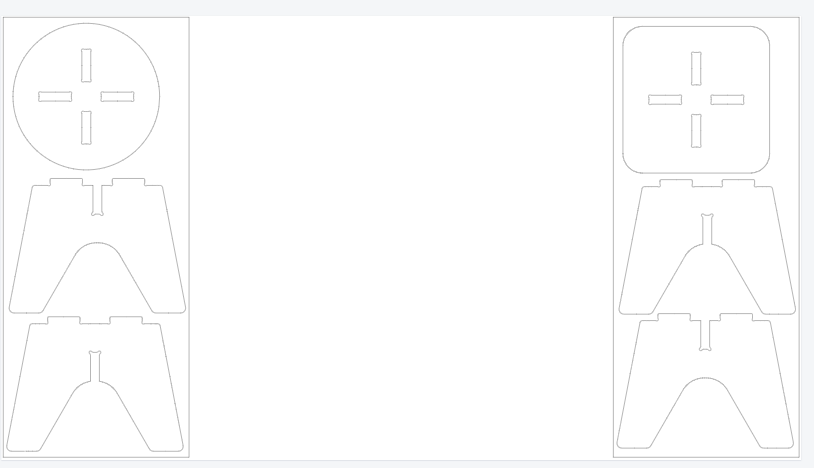
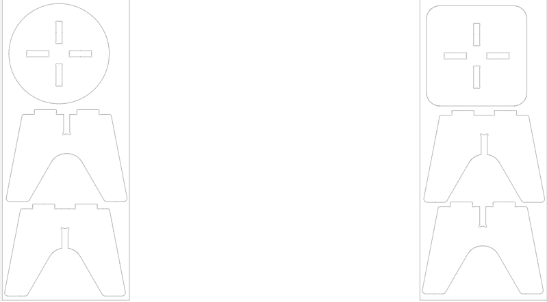
4. DXF Cutting Files and Layout
After confirming the feasibility of the CAD model, I exported the 2D profiles of the seat and chair legs as DXF files. The DXF files only retain the lines that actually need to be cut, including the outer contour of the seat, the central cross slot, the outer contour of the chair legs, the cross slot of the chair legs, and the dogbone corner structure.
After exporting, I imported the file into MasterCam for layout and tool path planning. During layout, it is necessary to ensure sufficient spacing between parts to avoid the cutter affecting adjacent parts when cutting one part, and also to avoid the cutting path hitting the screws or clamps that secure the plate.
This machining process uses an 8 mm flat end mill. To ensure stable cutting, I have set the machining sequence to first cut the internal structure and then the external contour:
- Cross slot at the center of the seat surface;
- Cross slot in the middle of the chair leg;
- Dogbone / T-bone details;
- Outer contour of the seat and chair legs.
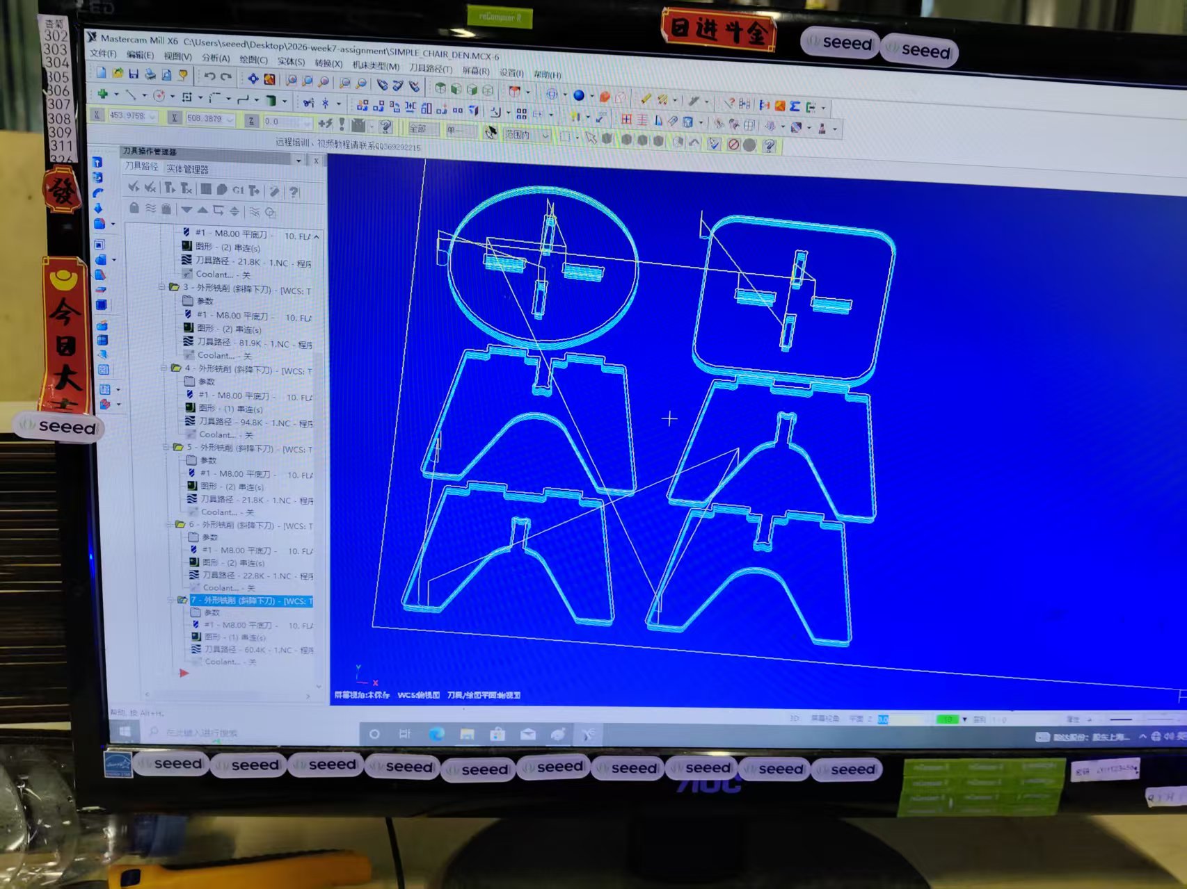
5. MasterCam X6 Generates G Code
In MasterCam X6, after importing the DXF file, I set the workpiece coordinate system, tool diameter, cutting depth, and feed rate. According to the results of the group test, the main parameters used this time are:
| Project | Parameter |
|---|---|
| Cutting Tool | 8 mm flat end mill |
| Spindle speed | 24000 rpm |
| Feed Rate | 5000 mm/min |
| Material | 18 mm MDF/HDF Board |
| Processing Strategy | Layered cutting, starting from the inside and then moving to the outside |
To avoid path errors, I check the tool path before generating G code. The key points to check include whether the notch is compensated on the inside, whether the outer contour is compensated on the outside, whether the tool will cut into the part body, and whether the path will pass through the fixture area.
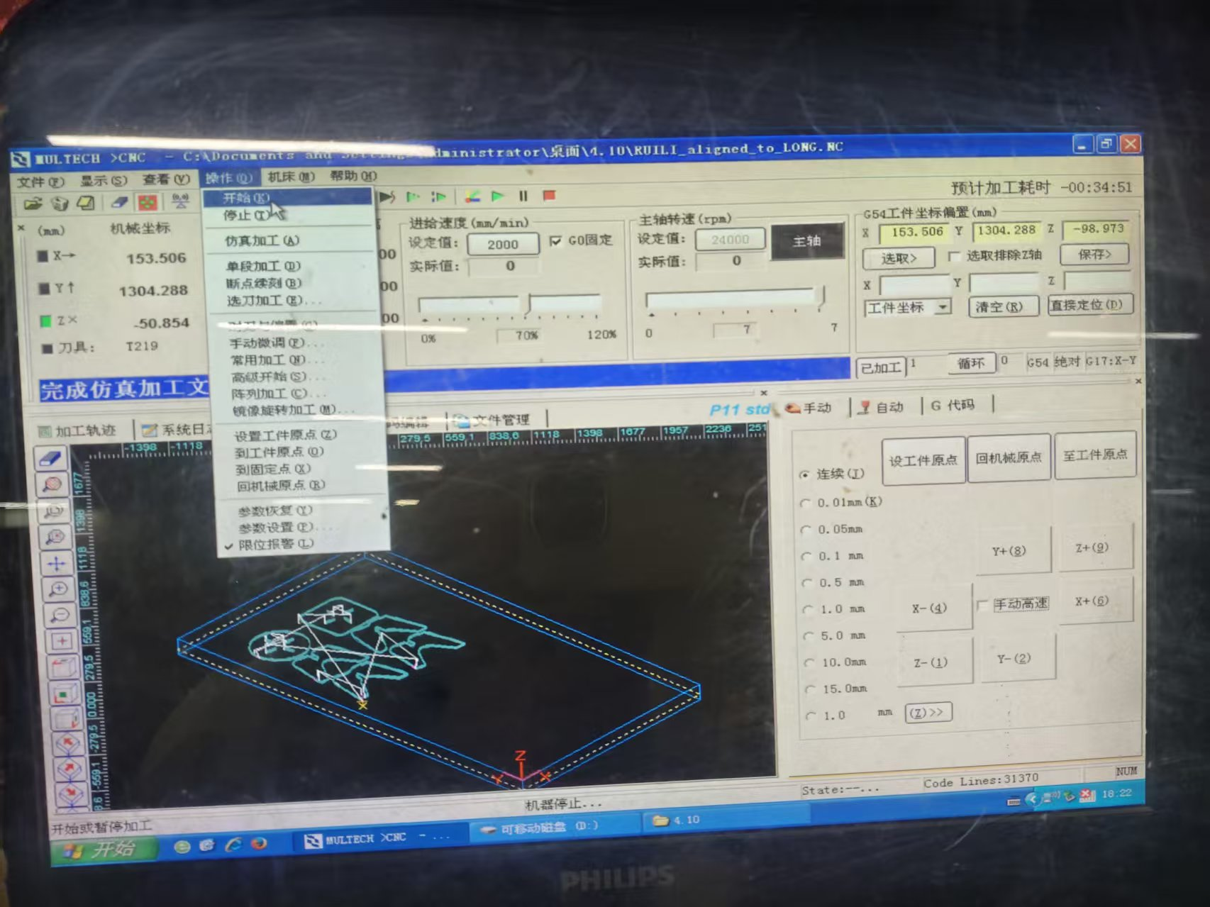
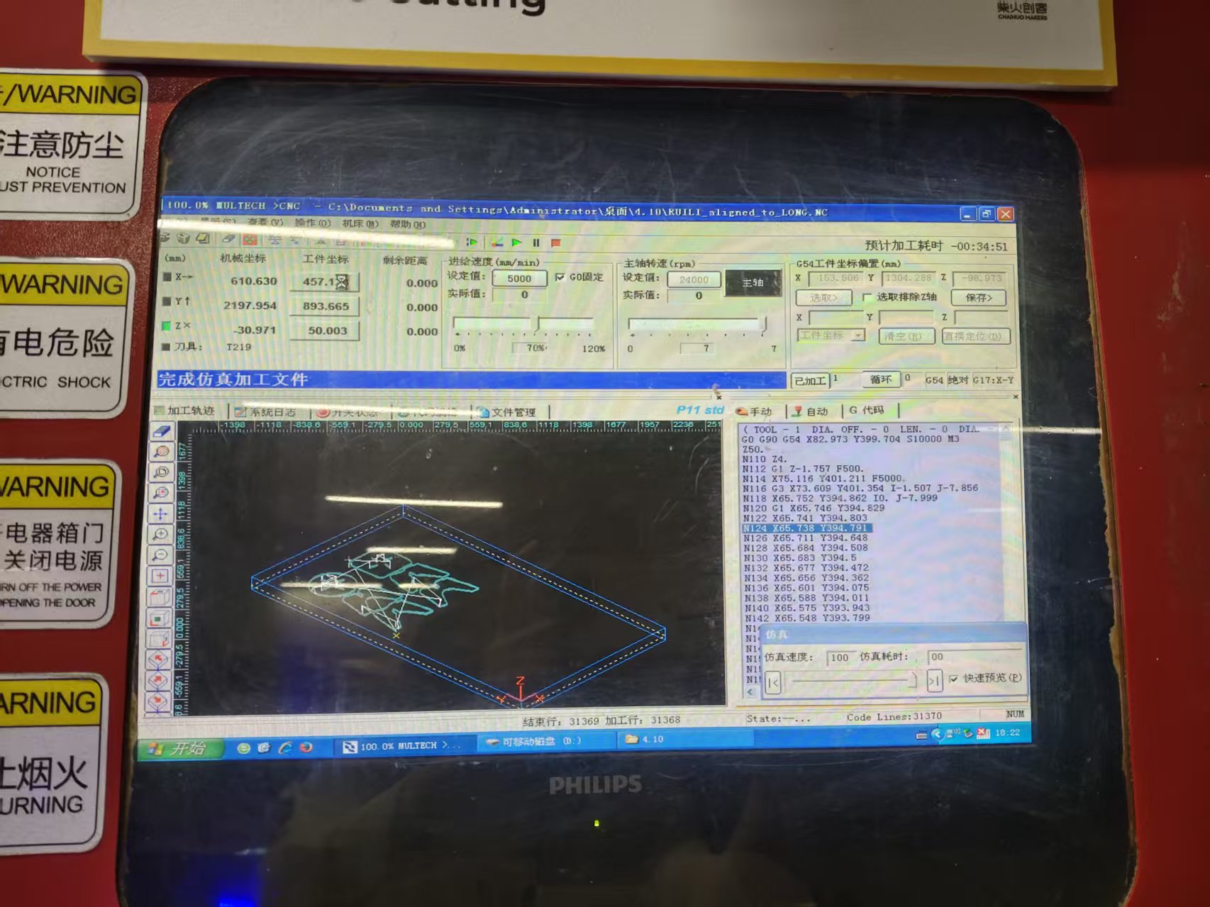
6.G Code Conversion and Machining Simulation
The G-code generated by MasterCam needs to be imported into the CNC milling machine control system and confirmed according to the format supported by the machine tool. Before the formal cutting, I first run a simulation to check whether the tool movement direction, machining depth, tool retraction position, and contour sequence are correct.
The significance of simulation is to expose risks in advance. For example, if the cutting depth in the Z direction is set incorrectly, the tool may cut through too deeply; if the contour compensation direction is reversed, the actual part size will be smaller or larger; if the outer contour is cut off prematurely, subsequent slot machining will lose a stable reference.
7. Numerical Control Milling Process
After confirming that there are no obvious issues in the simulation, we proceed to actual machining. Before machining, I completed the following preparations:
- Install and tighten the 8 mm flat-bottom end mill;
- Inspect the spindle, cooling, and dust removal systems;
- Secure the MDF board to the workbench;
- Set the X/Y/Z workpiece origin;
- Reconfirm that there are no extra items in the position of the emergency stop button and the processing area.

During machining, I observed the cutting state throughout, including cutting sound, chip evacuation, whether the plate moved, and whether the tool had abnormal vibrations. After the internal grooves and dogbone structures were completed, the outer contour was cut. This ensures that the part is separated from the plate only at the last moment, reducing shaking during the machining process.
After processing is completed, wait for the spindle to stop completely before removing the part. After removing the part, clean the burrs and wood chips on the edges, and check whether the notch is intact, the dogbone corner has been cut out, and the outer contour has any obvious chipping.
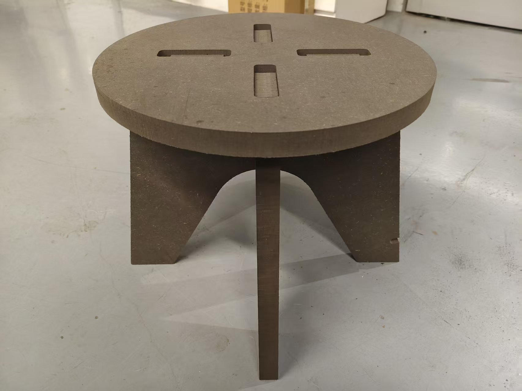
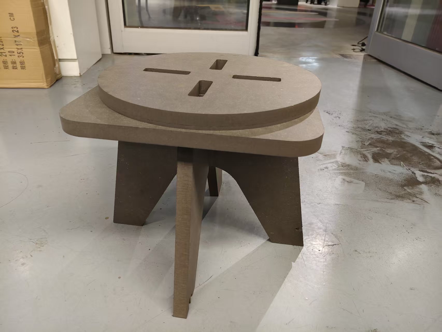
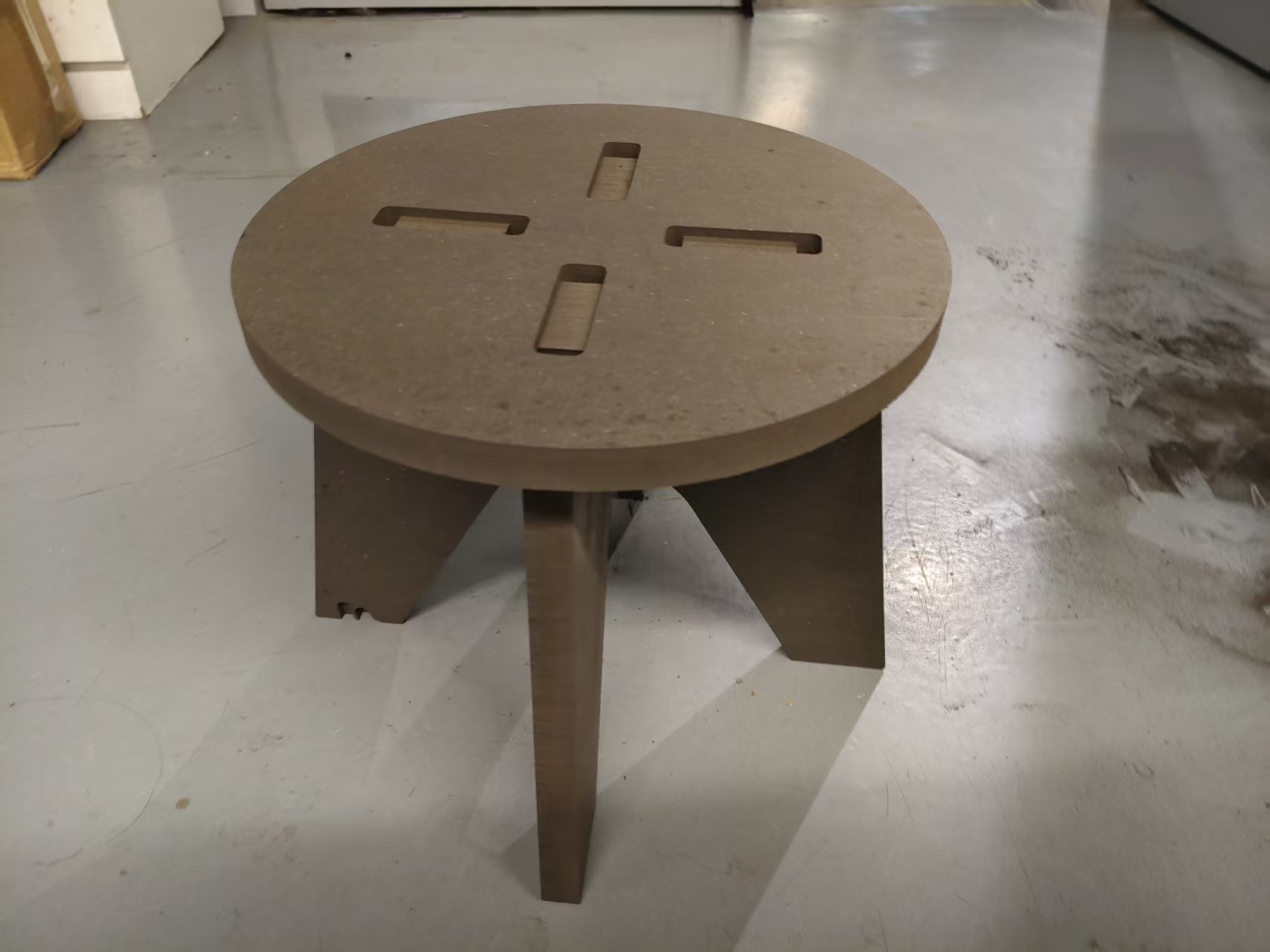
8. Finished Product Assembly and Effect Display
Finally, cross the two chair legs through the middle slot, and then insert the tenons at the top of the chair legs into the cross slot at the center of the chair seat. The entire process does not require screws or glue, and relies on the slot fit to complete the fixation.
After assembly, the chair can maintain basic stability, indicating that the slot width, tolerance, and dog bone structure have played their roles. Through this machining process, I have more intuitively understood the difference between CNC design and ordinary modeling: just because a model can be established on the screen does not mean it can be machined by a tool; material, tool, and assembly method must be considered together during design.
9. This Week's Summary
The biggest takeaway this week was understanding the complete process of CNC machining. CAD is responsible for defining the shape of parts, but whether machining can be successful ultimately depends on material thickness measurement, tool diameter, path compensation, internal angle treatment, cutting parameters, and clamping methods.
In the design of the personal chair, I applied the experience gained from group testing to the actual design: adjusted the slot width based on the measured board thickness, used Dogbone / T-bone to solve the internal right-angle problem, planned the tool path in the order of "inside first, outside second", and checked the path through simulation before machining. Finally, the transformation from the digital model to the physical chair was completed.