Week 3 - Computer Controlled Cutting
This week, we started to learn about Computer-Controlled Cutting. Cutting is one of the most fundamental and practical skills in digital manufacturing - from laser cutting to engraving machines, these devices can transform 2D design drawings into physical parts, serving as an important bridge from creativity to prototype.
Group Assignment:
As a group, systematically test the machining tolerance of the laser cutter. By designing and setting tolerance test rules (test size range from 3.0 mm to 3.6 mm), observe the actual cutting accuracy of the equipment under different dimensional parameters to determine the minimum gap size that the laser cutter can cut precisely. At the same time, adjust cutting parameters such as power and speed, record the complete process from designing the test specification to optimizing the cutting parameters, and update the results to the group page to complete the reference Merge Request.
Individual Assignment:
For the machining tolerance of the group experiment results, design a set of Press-fit Construction Kits using CAD software. During the design process, it is necessary to consider the material thickness and splicing structure so that the parts can be assembled based on the bracket using glue or screws. In addition, it is also necessary to use a Vinyl Cutter to cut self-designed graphics onto materials such as vinyl film, and record the equipment model, cutting and pressure parameters, as well as the problems encountered and solutions.
Overall, the focus of this week is not on creating complex works, but on understanding "how device precision affects design". Through tolerance testing, we can learn that there are differences between the dimensions in the design files and the actual cut dimensions; through the practice of pressing kits and engraving machines, we further learn how to apply these test results to actual production.
Group Assignment
1. Equipment Introduction
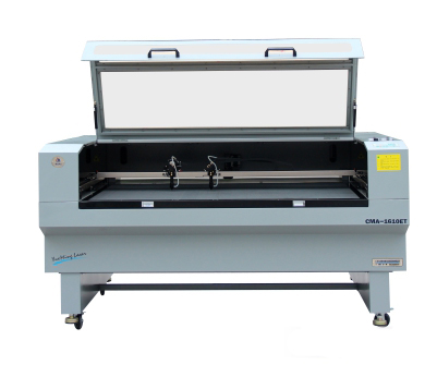
The group experiment this time uses the CMA 1610 Laser Cutter from Chaihuo Makerspace. This is a CO2 laser cutting device suitable for processing non-metallic materials such as wood, acrylic, and cardboard.
Before use, it is necessary to understand the basic safety operating specifications:
- Certification : Only authorized and trained users are allowed to operate the laser cutter, and new users must operate under supervision
- Personal Protection : Wear safety clothing during operation
- Operating Specification : Leave the device unattended during operation, and confirm that everything is normal before starting
- Emergency: Familiarize yourself with the location of the emergency stop button, and use a fire extinguisher or evacuate if necessary
- Cleanup after operation: Turn off all equipment and clean the workbench after use
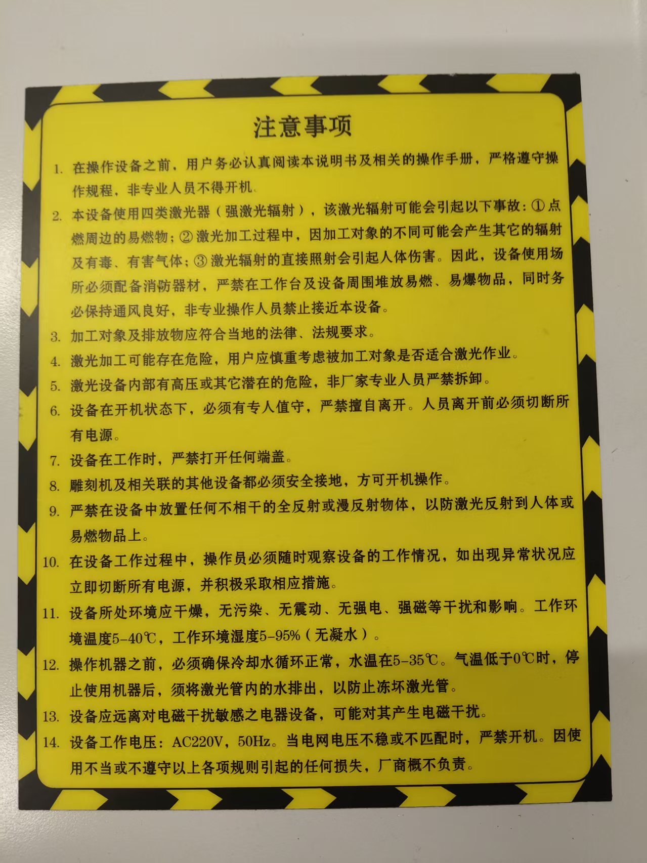
If the smoke increases significantly during the cutting process, it indicates that the exhaust system may not be working properly, or the material parameters are not set appropriately. After cutting is completed, the material should not be removed immediately. It is recommended to wait for a period of time to allow the smoke and odor to fully dissipate before opening the equipment to process the parts.
The main parameters of CMA 1610 are as follows:
| Parameter | Value |
|---|---|
| Laser Type | CO2 laser, wavelength 10 microns |
| Laser Power | 30–150 watts |
| Cutting speed | 0–600 mm/s |
| Maximum cutting thickness | 0–25 mm (depending on the material) |
| Applicable Materials | Non-metallic materials such as wood and acrylic |
Before operation, the cooling system, exhaust management system, and laser switch must be turned on in sequence to ensure that the equipment is in normal working condition. After the design file is imported via the installed software SmartCarve and parameter settings are completed, cutting can begin.
2. Laser Cutting Tolerance Test
2.1 What is cutting tolerance?
Laser cutting is not a line without width. When the laser beam cuts through the material, it ablates a portion of the material, and this burned width is commonly referred to as kerf . The kerf causes a deviation between the actual cutting size and the designed size.
For example, if we draw a 3 mm wide slot in CAD, when the laser cuts along both sides of the slot, it will burn away an additional portion of the material, and the final actual slot width may be greater than 3 mm. For press-fit structures, this deviation is very critical. If the slot is too wide, the part will be loose; if the slot is too narrow, the part cannot be inserted or is prone to breakage.
Therefore, before formally designing the pressing kit, it is necessary to first determine the actual cutting seam under the current equipment, materials, and parameters through testing.
2.2 Test Method
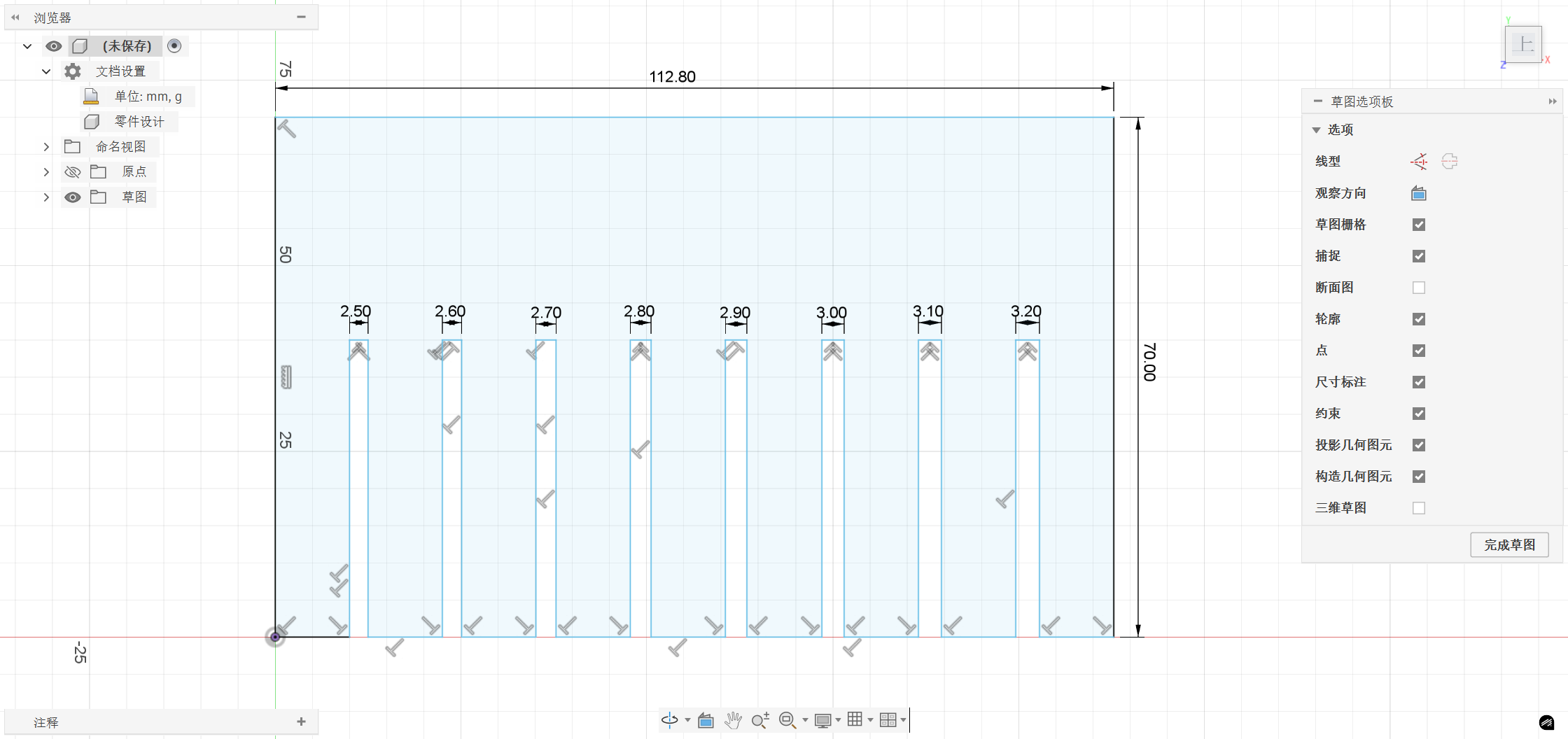
We designed a comb-shaped tolerance test gauge using Fusion 360. The test gauge contains multiple slots of different widths, which are used to test the insertion effect of 3 mm basswood boards at different slot widths.
The slot width range for this test is 2.5 mm to 3.2 mm , with a difference of 0.1 mm between each slot, for a total of 8 slots.
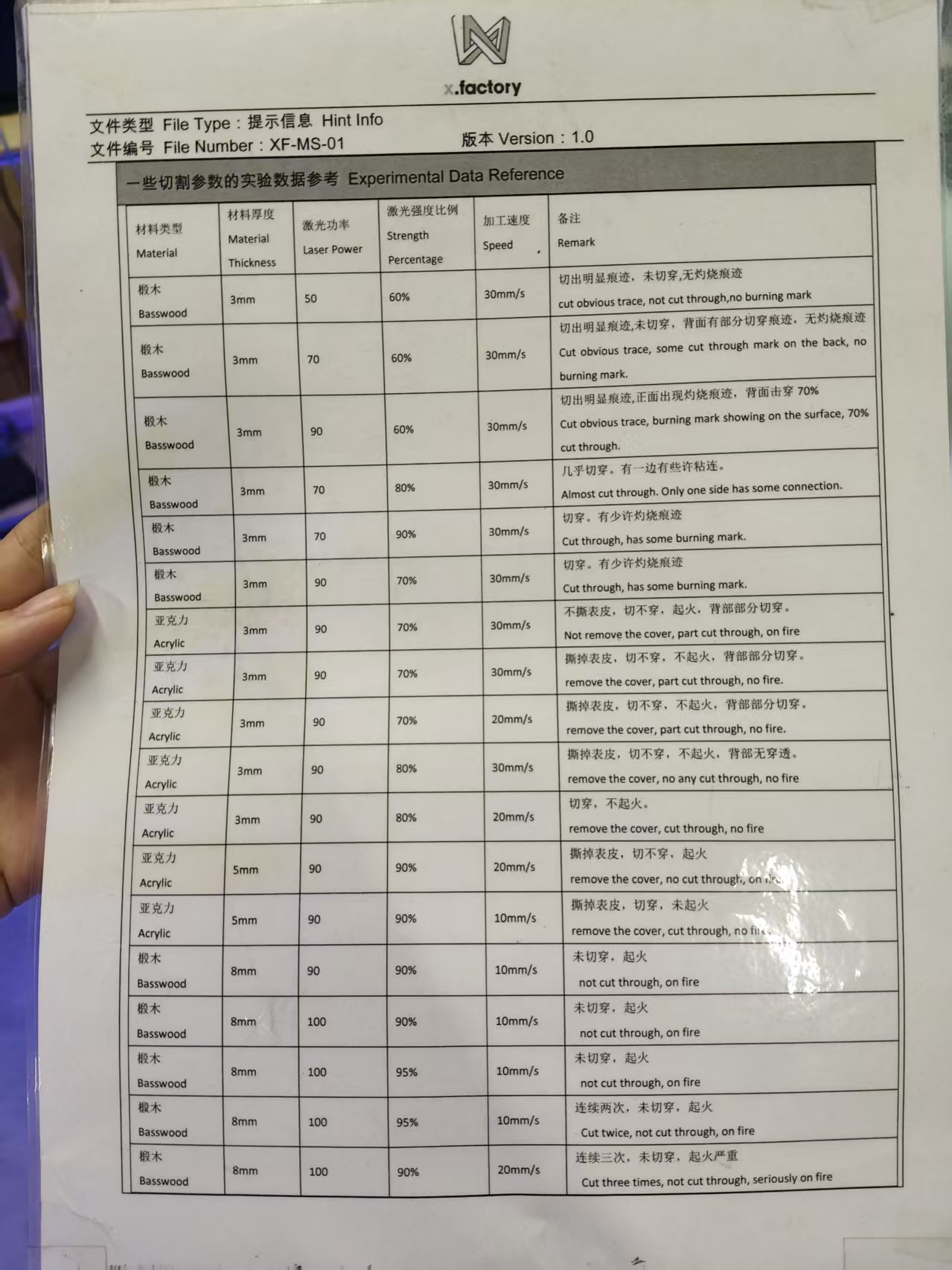
The materials and parameters used in the test are as follows:
| Project | Parameter |
|---|---|
| Device | CMA 1610 Laser Cutter |
| Material | 3 mm Basswood Board |
| Design Software | Fusion 360 |
| Control Software | SmartCarve |
| Test Slot Width | 2.5-3.2 mm |
2.3 Test Results
After the cutting is completed, we use a vernier caliper to measure the actual width of each slot and record the difference between the designed dimension and the actual dimension.
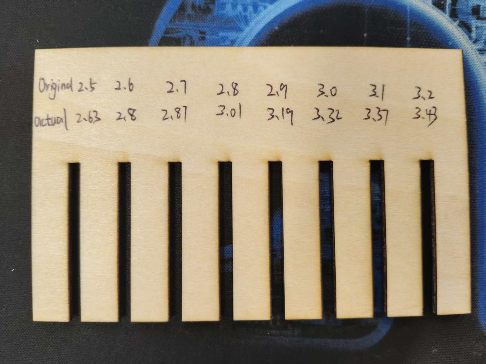
After cutting is completed, use a vernier caliper to measure the actual width of each slot, and the results are recorded as follows:
| Slot | Design Dimensions (mm) | Measured Dimensions (mm) | Difference (mm) |
|---|---|---|---|
| 1 | 2.5 | 2.63 | 0.13 |
| 2 | 2.6 | 2.8 | 0.2 |
| 3 | 2.7 | 2.87 | 0.17 |
| 4 | 2.8 | 3.01 | 0.21 |
| 5 | 2.9 | 3.19 | 0.29 |
| 6 | 3 | 3.32 | 0.32 |
| 7 | 3.1 | 3.37 | 0.27 |
| 8 | 3.2 | 3.43 | 0.23 |
| Average Difference | 0.22 | ||
| Unilateral slit (average difference ÷ 2) | 0.11 |
2.4 Conclusion
Since both sides of the slot will be ablated by the laser, the average difference needs to be divided by 2 to obtain the single-sided kerf width. According to the results of this measurement, under the current equipment, material, and parameter conditions, the single-sided kerf of CMA 1610 on a 3 mm basswood board is approximately 0.11 mm.
That is to say, if you want the actual width of the slot to be close to 3 mm, you can set the slot width during design as follows:
Design slot width = Material thickness - 2 × Single-sided kerf
Design slot width = 3.00 mm - 2 × 0.11 mm = 2.78 mm
Therefore, in the subsequent press-fit assembly kit, I set the slot width to 2.78 mm, so that the actual slot width after cutting is as close as possible to 3 mm.
3. Collaboration Group: Upload to GitLab Repository
In addition to device testing, this week we also need to update the group assignment content to the Fab Academy group page. The group page uses a GitLab repository for collaboration, so it needs to be completed through Fork, modification, preview, and Merge Request.
The group pages and repositories used this time are as follows:
- Group Page: https://fabacademy.org/2026/labs/chaihuo/
- Group Repository: https://gitlab.fabcloud.org/academany/fabacademy/2026/labs/chaihuo/site
The basic process is as follows:
- Fork the GitLab group repository to your own account.
- Clone the personal repository to your local computer.
- Install Node dependencies according to the README file in the repository, for example, run
yarn. - Use
yarn startto preview the page locally. - Update personal information in
docs/students/students.md. - Add the group assignment document under the path
docs/week3/Beijing_lab/. - Add experimental images and videos under the path
static/img/week3/Beijing_lab/. - Use
yarn buildlocalto generate local HTML files and check if the pages are working properly. - After submitting the modifications, initiate a Pull Request to the group repository and wait for the administrator to review and merge.
Through this part of the operation, I have also further familiarized myself with the GitLab collaboration process. The assignments in Fab Academy are not just about completing experiments individually; they also require organizing the experimental process into web documents and submitting them to a public page via version control tools.
Individual Assignment
1. Press-fit Construction Kit
1.1 Design Concept
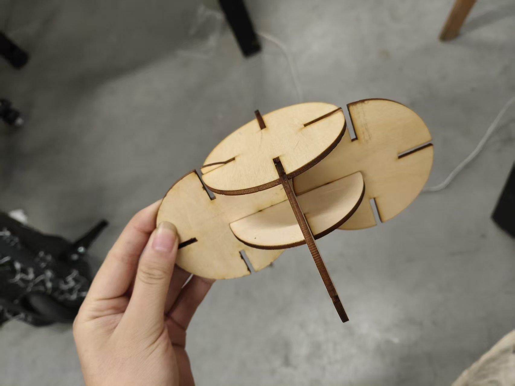
Based on the slotting results measured from the group project, I designed a set of circular slotted press-fit assembly kits. Each part is a circular sheet structure with four evenly distributed slots on the edge. Multiple identical parts can be vertically inserted into each other through the slots to form different spatial structures.
The core of this structure is Press-fit , which relies on friction and slight interference between materials to achieve fixation. It does not require glue, screws, or other connectors, making it ideal for practicing laser cutting parameters and tolerance compensation.
The material for this time is 3 mm basswood board . According to the previous kerf test, the unilateral kerf is approximately 0.11 mm , so the designed width of the slot is set to 2.78 mm .
1.2 Design Process
Step 1: Create a new sketch
Open Fusion 360, click on the top left cornerCreate Sketch, selectXYas the floor plan flowchart.
Step 2: Draw a circle
Select the Center Diameter Circle tool, use the origin as the center, and enter the diameter 80 mm . This way, a circular part suitable for handheld operation and splicing can be obtained.
Step 3: Draw the card slot
Draw a rectangular slot on the circular edge, with the slot width set to 2.78 mm. This dimension is derived from the group tolerance test results:
Material Thickness = 3.00 mm
Single-sided slit = 0.11 mm
Design slot width = 3.00 - 0.11 × 2 = 2.78 mm
During cutting, the laser ablates approximately 0.11 mm on each side of the slot, so the actual width of the cut slot will be close to 3.00 mm, just suitable for inserting a 3 mm plate.
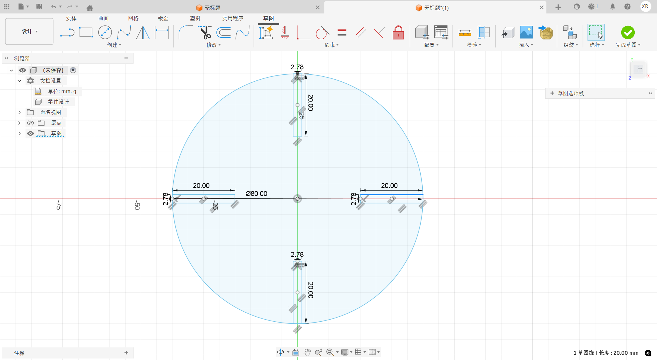
Step 4: Copy the card slot
To enable the parts to be plugged in from multiple directions, I arranged the card slots in a circular pattern centered on the circle's center, creating four evenly distributed card slots. This allows the parts to be combined horizontally, vertically, or crosswise, providing a higher degree of assembly freedom.
Step 5: Export the cutting file
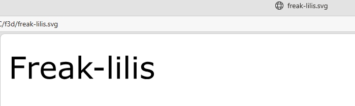
After completing the sketch, export the design as .dxf file for importing into the laser cutting software. The source file is also saved in .f3d format of Fusion 360 for easy parameter modification later.
1.3 Laser Cutting Parameters
The cutting parameters for this pressing kit are as follows:
| Parameter | Specific parameters |
|---|---|
| Device | CMA 1610 |
| Material | 3mm basswood board |
| Laser Power | 90% |
| Laser Intensity Ratio | 60% |
| Cutting speed | 30 mm/s |
| Number of Cuts | 1 time |
1.4 Test Results
After the first trial cut, the parts can be smoothly inserted between each other, the slot fit is relatively tight, and the structure can be fixed by friction without obvious looseness. This indicates that the 2.78 mm slot width calculated based on the 0.11 mm single-sided kerf is effective for the current material and cutting parameters.
If more complex or larger-sized structures need to be made later, the slot width can be further fine-tuned based on the feel. For example, if the plugging is too tight, the slot width can be increased by 0.05 mm; if the plugging is too loose, the slot width needs to be appropriately reduced.
Through this exercise, I have more intuitively understood why the press-fit structure cannot be designed solely based on the nominal thickness of the material. In actual processing, slits, tolerances, and material elasticity must be considered; otherwise, even if the CAD dimensions appear correct, the actual parts may not be able to be assembled.
2. Engraving Machine Cutting (Vinyl Cutting)
2.1 Design Concept
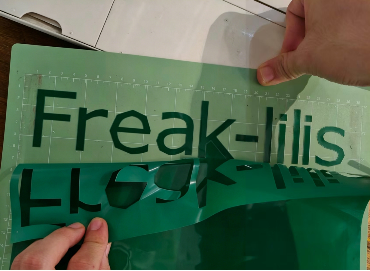
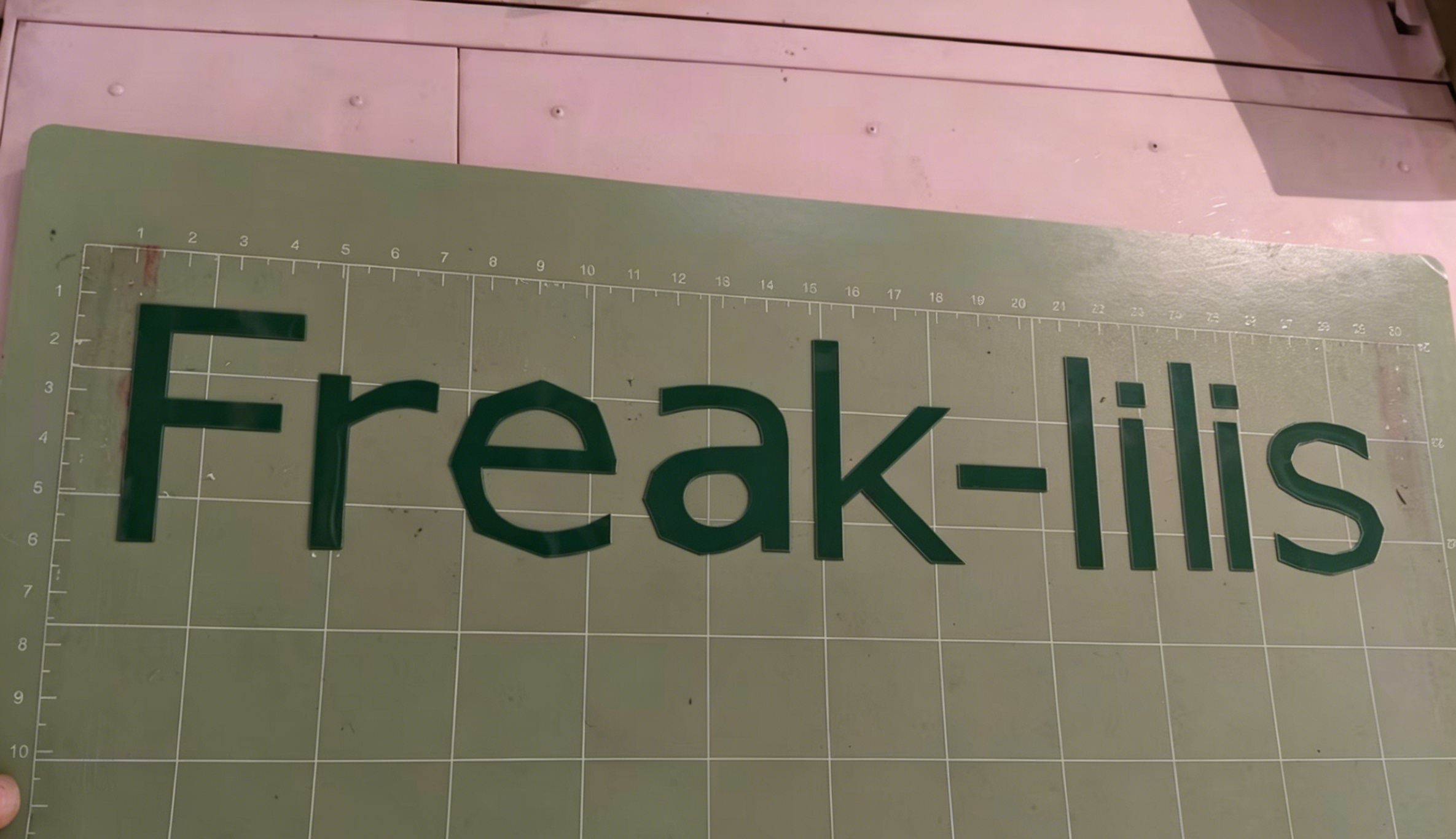
During this engraving machine operation, I chose to use FreakStudio-lilis as the cutting pattern. Among them, FreakStudio is the name of my personal studio, and lilis is my personal alias. When combined, they can serve as a personal logo. After making it into a sticker using the engraving machine, it can be affixed to devices, works, or toolboxes for personal signature use.

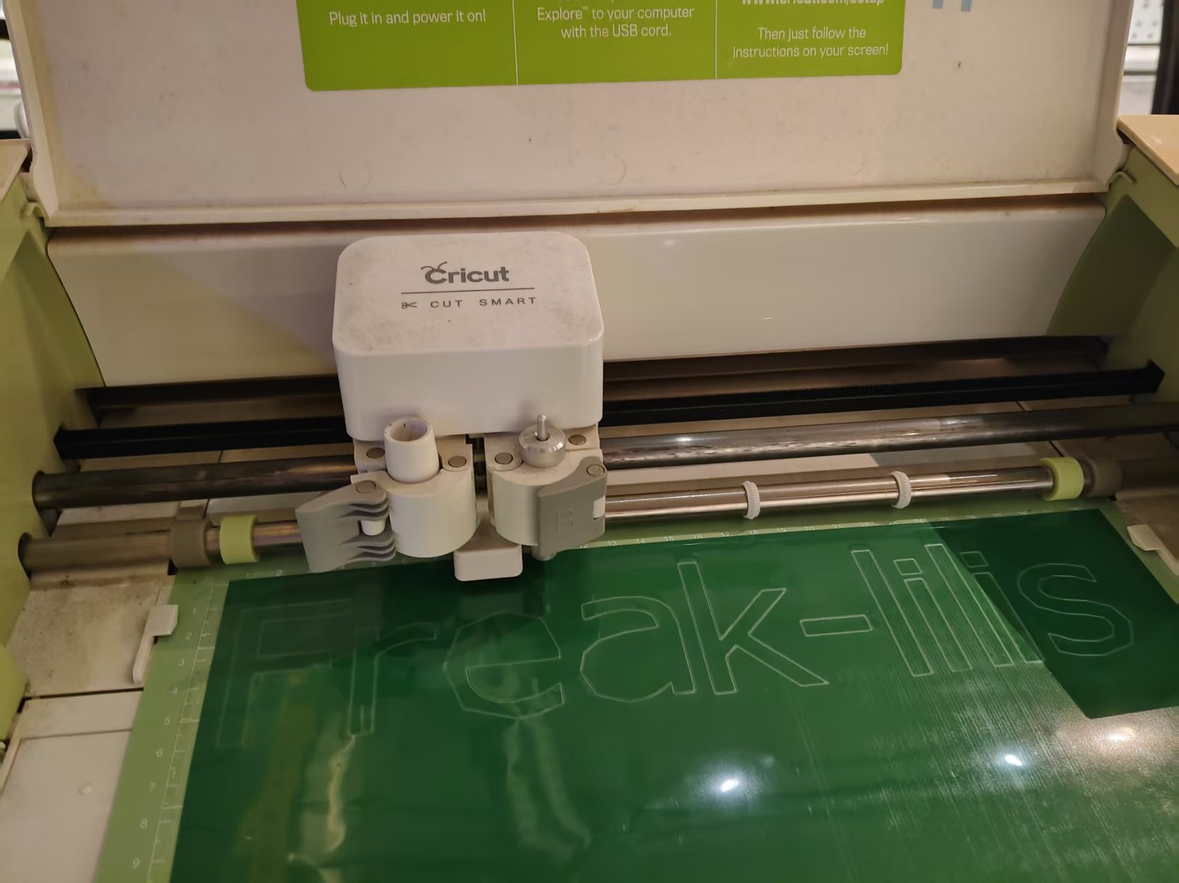
2.2 Equipment Introduction
The equipment used this time is the Cricut X1 Vinyl Cutter from the Maker Space. The vinyl cutter cuts patterns on vinyl film using a small blade. Ideally, the blade only cuts through the top film layer without cutting the backing paper. After cutting, the excess film needs to be peeled off, and then a transfer film is used to apply the pattern to the target surface.

| Parameter | Value |
|---|---|
| Device Model | Cricut X1 |
| Material | Green vinyl film |
| Material Thickness | Thin film material, with a relatively small thickness |
| Supporting Software | Cricut Design Space |
| Design Software | Inkscape |
2.3 Design Document Production
Step 1: Enter text in Inkscape
Open Inkscape, use the text tool (shortcut key T) to type FreakStudio-lilis on the canvas, then select an appropriate font and font size to ensure the overall proportion is harmonious.
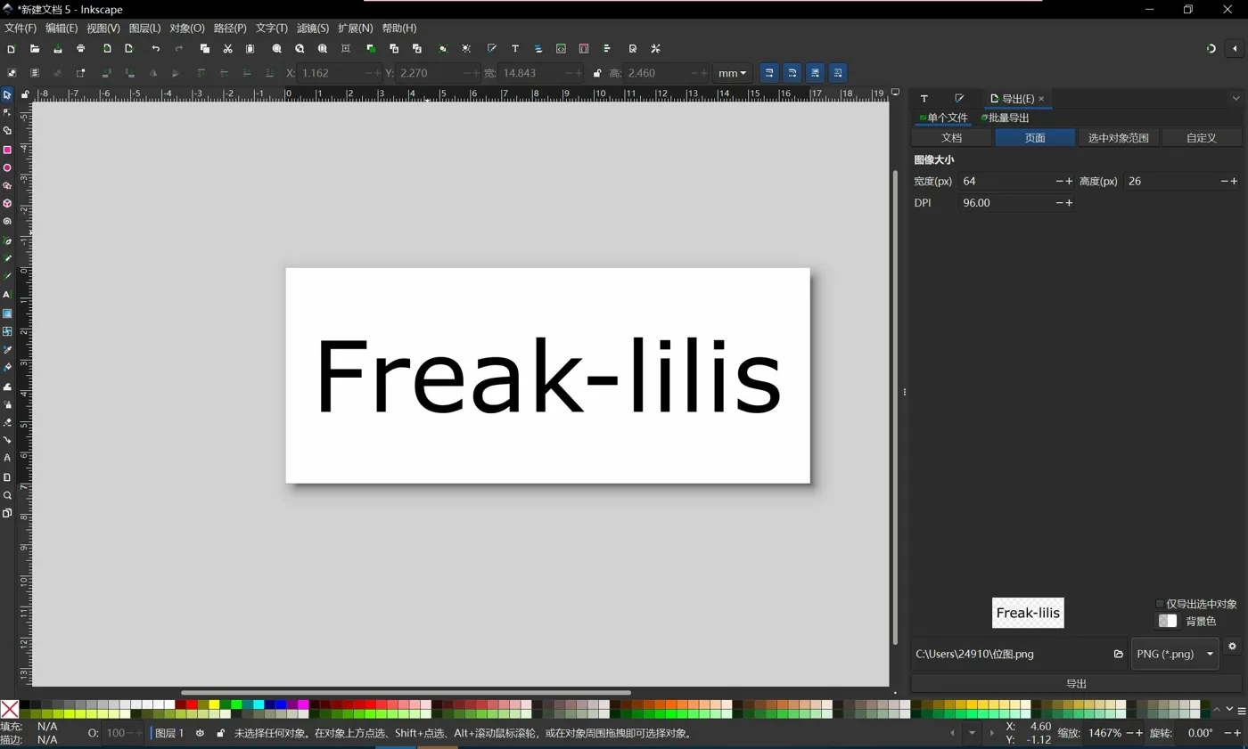
Step 2: Convert text to path
The engraving machine cuts not "text objects" but vector paths. Therefore, before exporting, you need to convert text to paths first:
- Select the text using the Selection Tool.
- Click the top menu Path → Object to Path.
- After conversion, each letter becomes an editable vector outline.
This step is crucial. If it is not converted to a path, issues such as missing fonts, misaligned patterns, or unrecognizable cutting paths may occur after importing into the engraving machine software.
Step 3: Export the SVG file
After completing the path conversion, save the file as Plain SVG format. Plain SVG is more suitable for transfer between different software and has better compatibility than the default SVG in Inkscape.
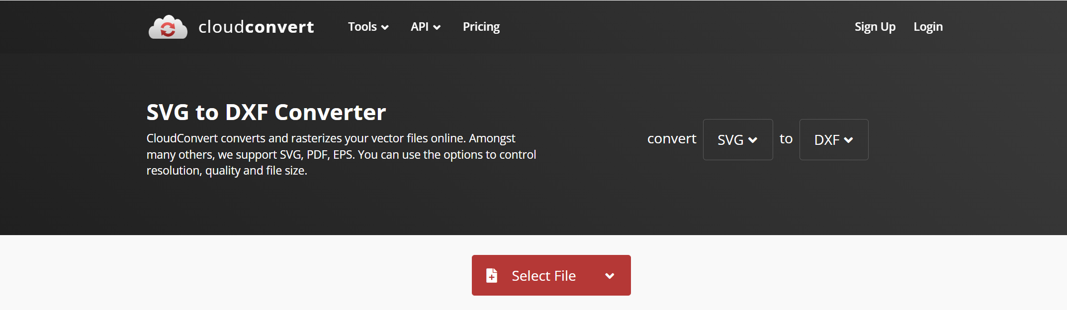
Step 4: Convert SVG to DXF format
Since Cricut Design Space has certain requirements for file formats, I tried to convert SVG to DXF format. An error occurred when Inkscape directly exported DXF, so I first saved it as Plain SVG and then converted SVG to DXF using an online conversion tool.
Conversion Tool: https://cloudconvert.com/svg-to-dxf
2.4 Machine Preparation
Before cutting, you need to prepare materials and a cutting mat first:
- Cut the vinyl film to the appropriate size.
- Confirm that the surface of the film is clean, without obvious creases or bubbles.
- Smoothly apply the film onto the cutting mat and align it with the grid lines.
- Gently flatten with your hand or a scraper to prevent the material from lifting during cutting.
- Feed the cutting mat into the Cricut X1 and complete the fixation as prompted by the software.
2.5 Cutting Parameter Settings
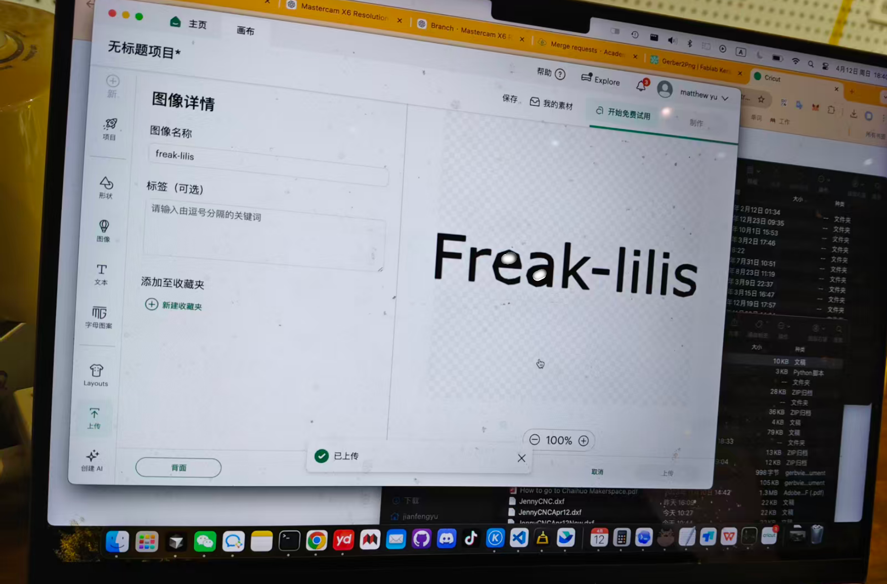
After importing a DXF file into Cricut Design Space, you need to adjust the pattern size and cutting position, trying to keep the pattern within the material range while minimizing material waste.
The parameters set this time are as follows:
| Parameter | Value |
|---|---|
| Material Type | Ordinary vinyl film |
| Cutting speed | 20 mm/s |
| Cutting Pressure | 80 g |
| Cutting Method | Half cut, retain backing paper |
2.6 Problems Encountered and Solutions
When creating the file, the first problem encountered was that Inkscape reported an error when directly exporting DXF and could not save it properly. Later, I changed to first saving it as Plain SVG and then converting it to DXF via CloudConvert, and the file could be imported into Cricut Design Space normally.
The second issue is that the pressure was too low during the first test cutting, causing some strokes to not be completely cut through. For text stickers, if thin lines are not cut through, it is easy to pull up the pattern along with the excess film when removing it later. The solution is to appropriately increase the cutting pressure and retest, resulting in significantly more stable cutting results.
2.7 Summary
Through this engraving machine practice, I fully experienced the process from pattern design, path conversion, file format processing, material fixation to final cutting. Finally, the FreakStudio-lilis text pattern could be cut out normally and used as a personal logo sticker.
The most important step in this exercise is to convert text to paths . Only after converting to paths can the engraving machine software recognize the text as a cuttable vector outline. At the same time, the cutting pressure also needs to be adjusted according to the material state; too low pressure will result in incomplete cutting, while too high pressure may cut through the backing paper.
Attachment

[!NOTE]
AI Assistance:
During the preparation of this documentation, ChatGPT \(GPT\-4\) was used as a language assistance tool.
It helped with sentence polishing and translation from Chinese to English to improve readability and clarity.