Week 9 - Input Devices
This week we start learning about Input Devices . Input devices are the entry point for embedded systems to perceive the external world. They can convert real-world information such as button presses, temperature, humidity, light, distance, sound, etc., into electrical signals, which are then read and processed by the microcontroller.
The signal forms output by different input devices are not the same. Some devices output digital signals, which have only two states: high level and low level; some devices output analog signals, where the voltage changes continuously with the external environment; and some sensors output data through communication protocols, such as OneWire, I2C, SPI, or UART. Therefore, the focus this week is to understand the types of input signals and learn how to read sensor data on a microcontroller.
Group assignment:
The group assignment mainly involves using test equipment such as oscilloscopes and multimeters to observe the electrical characteristics of input devices and development boards. By measuring the digital signals of the key module with an oscilloscope, analyze the changes in high and low levels when it is pressed and released; at the same time, use a multimeter to measure the power supply voltage of the development board and the current in the GPIO branch to understand the relationship between power supply, signal, and load in input testing.
Individual assignment:
Individual assignments require integrating at least one sensor on a self-designed microcontroller development board and implementing data acquisition and processing through programming. This time, I choose to use the DHT22 temperature and humidity sensor, read temperature and humidity data via MicroPython, and output the results in the REPL. Finally, based on the sensor parameters and actual readings, a simple analysis of the measurement accuracy is conducted.
Overall, the focus of this week is not to implement complex sensor fusion, but to complete the entire process from hardware connection, protocol understanding, code reading to data verification. Through these basic exercises, a foundation can be laid for environmental perception and interactive control in subsequent projects.
Group Assignment
Group Assignment Page: https://fabacademy.org/2026/labs/chaihuo/docs/week9/chaihuo/week9_group_assignment
1. Input Signal Type
Before the formal measurement, we first distinguished several common types of input signals.
| Signal Type | Features | Typical Equipment |
|---|---|---|
| Digital Signal | There are only two states: high level and low level | Button, Touch Switch, Limit Switch |
| Analog Signal | The voltage changes continuously and requires ADC reading | Potentiometer, Photoresistor, Analog Temperature Sensor |
| Bus Communication Signal | Transmit data via Communication Protocol | I2C Sensor, SPI Sensor, DHT22 |
Digital signals are typically used to determine "whether a certain event has occurred", such as whether a button has been pressed. Analog signals, on the other hand, can represent continuously varying physical quantities, such as position or light intensity. Bus communication signals encode data into a specific protocol, and the microcontroller needs to read it according to the protocol timing.
2. Measure digital signals
This group test uses the button module as a digital input device. The output terminal of the button module is connected to the oscilloscope probe, and GND is connected to the oscilloscope ground. By pressing and releasing the button, the level change is observed.
To verify the digital signal output of the key module, we connected the oscilloscope probe to the DIN pin of the module, and the ground clip to GND. This way, the oscilloscope can directly observe the waveform of the key output signal changing over time.
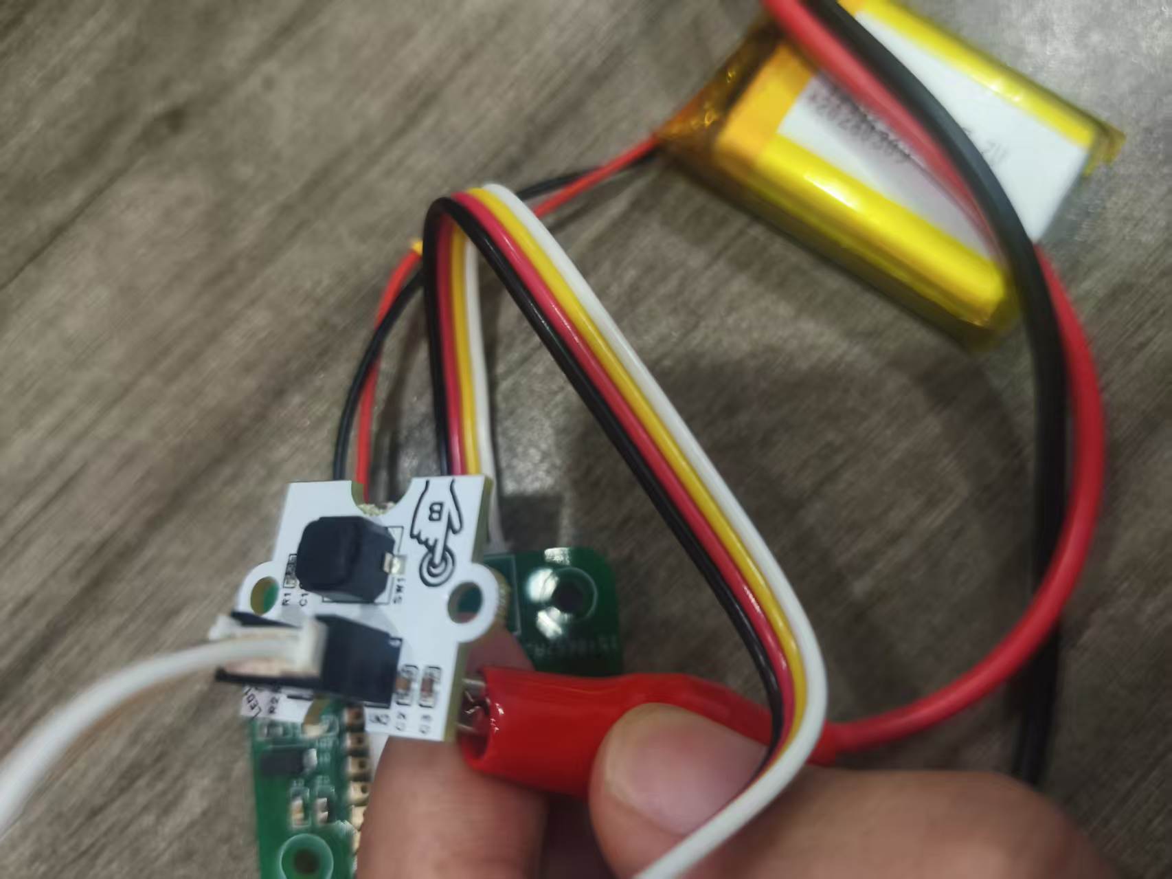
After completing the wiring, press the button on the module, and the oscilloscope successfully captures the high and low level transition waveforms. The rising and falling edges of the waveform are synchronized with the button action, indicating that the button module can stably output digital signals.
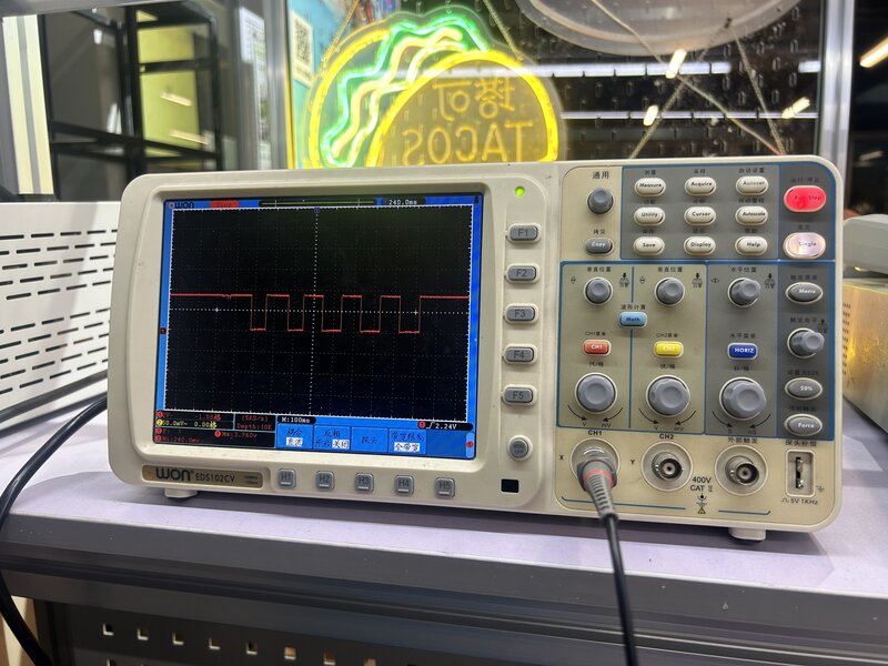
In an oscilloscope, the vertical axis represents voltage, and the horizontal axis represents time.
The parameters observed this time are as follows:
| Project | Observation Results |
|---|---|
| Vertical Scale | 2 V / div |
| Waveform Height | Approximately 1.75 div |
| Estimated Voltage | 2 V × 1.75 ≈ 3.3 V |
| Horizontal Scale | 100 ms / div |
| One cycle | Approximately 2 div |
| Estimation Cycle | 100 ms × 2 = 200 ms |
3. Use a multimeter to measure the electrical parameters of the development board
In addition to using an oscilloscope to observe the waveform of the input signal changing over time, we also used a multimeter to perform basic measurements on the power supply and GPIO outputs on the development board. An oscilloscope is more suitable for observing the process of signal changes, while a multimeter is suitable for quickly confirming static or average values such as voltage, current, and conduction state.
The platform for this test is the Week 6 self-made PCB. Each student's board has an ESP32 module (XIAO ESP32-C3 or ESP32-S3) soldered on it, with power pins and GPIO headers brought out. After completing the circuit board soldering in Week 8, we directly measured the VCC/GND power rails on the board, as well as the GPIO output lines used to drive LEDs, water pumps, or other actuators.
3.1 Review of Multimeter Functions
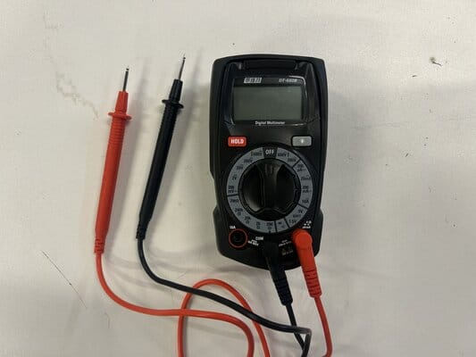
A multimeter can measure voltage (V), current (A), and resistance (Ω), and can also be used for continuity testing. Before use, it is necessary to select the appropriate range and probe jack according to the measurement object.
| Part | Function |
|---|---|
| Display | Displays the measured value; if the probe polarity is reversed, a negative value will be displayed |
| Selection | Select voltage, current, resistance, or continuity test range |
| 10A Jack | Used to measure currents greater than 200 mA |
| COM Jack | Black test lead, connect to the circuit ground |
| VΩmA Jack | Red test lead, used for measuring voltage, resistance, and current less than or equal to 200 mA |
The DT-660B multimeter from Chaihuo Laboratory was used this time.
3.2 Measure Voltage
Voltage represents the potential difference between two points. When measuring voltage, the multimeter needs to be connected in parallel with the two points being measured: the red probe is connected to the high-potential point, and the black probe is connected to GND.
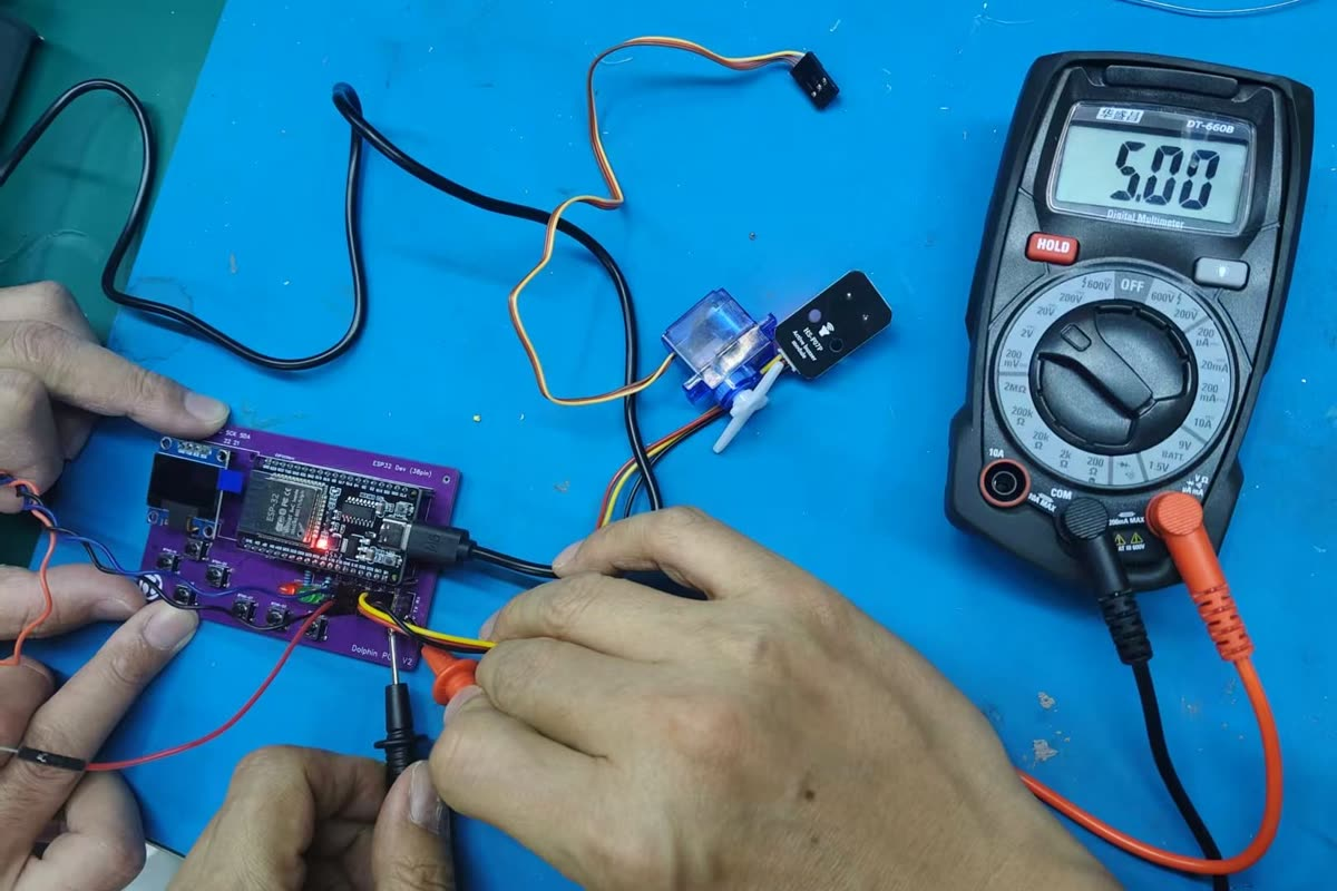
We measured the voltage between GND and VCC on the ESP32 development board. The multimeter showed 5.00 V, indicating that the 5 V power rail can output normally after the circuit board is soldered and powered.
| Measurement Location | Measurement Method | Reading | Description |
|---|---|---|---|
| GND and VCC | Parallel measurement of voltage | 5.00 V | 5 V power rail is normal |
This result can serve as the basic verification for subsequent input device testing: if the power supply voltage is abnormal, the output signals of the sensor or key module may also be unstable.
3.3 Measuring Current
Current represents the flow of charge in a circuit. When measuring current, a multimeter needs to be connected in series to the circuit, which means breaking the original current path and connecting the multimeter in the middle so that the current passes through the multimeter.
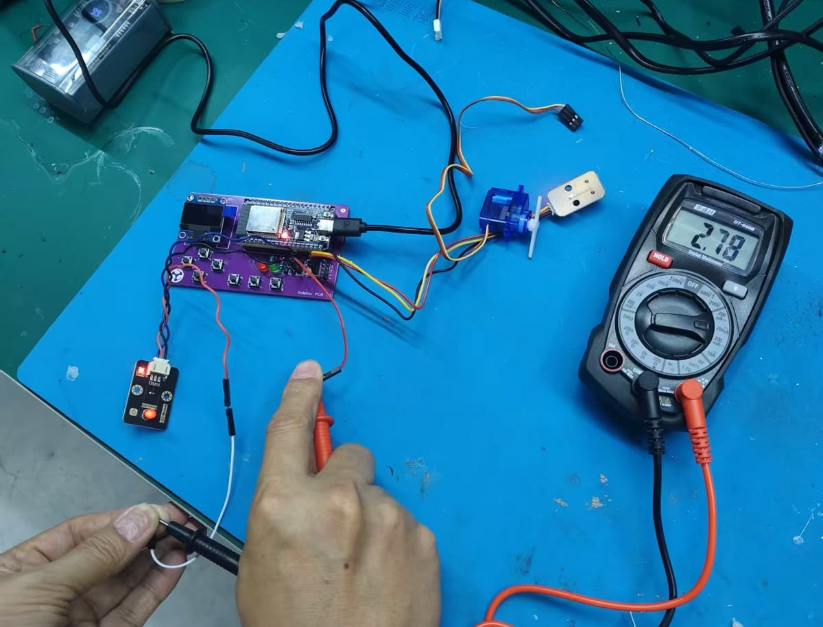
We measured the current in the branch between GPIO 19 and GND when the ESP32 output was in working condition. The multimeter showed 2.78 mA .
| Measurement Location | Measurement Method | Reading | Description |
|---|---|---|---|
| GPIO 19 and GND | Series measurement current | 2.78 mA | The current in the GPIO output branch is small and within the safe range |
Based on the measured voltage and current, the power of this branch can be estimated:
Through this step of measurement, we have not only confirmed whether the power supply rail is normal, but also verified that the current in the GPIO output branch does not exceed the range of common small-signal outputs. Compared with the oscilloscope waveform, the multimeter reading more intuitively reflects the power supply status and load size of the circuit.
4. Comparison between Analog Signals and Digital Signals
Although the actual measurement this time was of the key digital signal, the signal characteristics of analog input devices were also discussed in the group assignment. The output of an analog sensor is not simply 0 and 1, but a continuously varying voltage.
For example, the voltage at the output terminal of a potentiometer varies continuously with the position of the . If the power supply is 3.3 V, the potentiometer output may vary between 0 V and 3.3 V. A microcontroller cannot directly use this continuous voltage as digital data, so it needs to pass through ADC (Analog-to-Digital Converter) to convert the voltage into a digital value.
The differences between digital signals and analog signals can be summarized as follows:
| Project | Digital Signal | Analog Signal |
|---|---|---|
| Signal Morphology | High and low level transitions | Continuous Voltage Variation |
| Typical waveform | Square wave or step waveform | Smoothly changing curve |
| Reading Mode | GPIO Read 0 / 1 | ADC Read Value |
| Applicable Devices | Buttons, Switches | Potentiometer, Photosensitive Sensor |
This observation has allowed me to more clearly understand the differences in input devices. For inputs such as buttons, the program primarily determines high and low levels; for analog sensors, the program needs to read the ADC value and further convert it into an actual physical quantity.
6. Principles of Common Input Interfaces
In addition to directly outputting digital or analog signals, input devices may also output data through a communication protocol.
6.1 ADC Analog-to-Digital Conversion
ADC is used to read analog voltage. The microcontroller converts the input voltage into a digital value. For example, the range of a 12-bit ADC is typically 0-4095, where a larger value indicates a higher input voltage.
6.2 I2C Bus
I2C uses SDA and SCL two signal lines for communication, suitable for connecting multiple low-speed sensors, such as temperature and humidity sensors, barometric pressure sensors, OLED displays, etc. Each device is distinguished by its address.
6.3 SPI Bus
SPI typically uses signal lines such as MOSI, MISO, SCK, and CS, with a relatively high speed, making it suitable for connecting displays, memories, or high-speed sensors.
6.4 Single Bus / OneWire Class Protocol
The DHT22 uses a communication protocol similar to a single-wire bus, requiring only one data line to transmit temperature and humidity data. It has relatively strict timing requirements, so it usually requires the use of an existing library for reading.
Individual Assignment
1. Sensor Selection
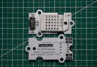
For this individual assignment, I chose to use the DHT22 Temperature and Humidity Sensor as the input device. The DHT22 can simultaneously measure ambient temperature and relative humidity, with its output being a digital signal, making it suitable for learning sensor data acquisition.
The advantage of DHT22 is that its wiring is simple, requiring only VCC, GND, and one data pin; meanwhile, the dht library has already been provided in MicroPython, which allows for relatively convenient data acquisition.
The materials for the input devices used this time are as follows:
| Material | Quantity | Function |
|---|---|---|
| DHT22 Temperature and Humidity Sensor Module | 1 | Collect temperature and humidity |
| Independently developed development board | 1 | As the master control platform |
| Connecting Line | several | Connect the sensor to the development board |
2. Hardware Connection
First, according to the module pin definition, connect the sensor's VCC and GND to the power and ground interfaces of the development board respectively, then connect the data pin DIO to the GPIO pin of the development board.
The original record uses GPIO20, while the code actually uses GPIO6. During the final test, it is necessary to ensure that the hardware wiring and the pin numbers in the code are consistent; otherwise, the program will fail to read.
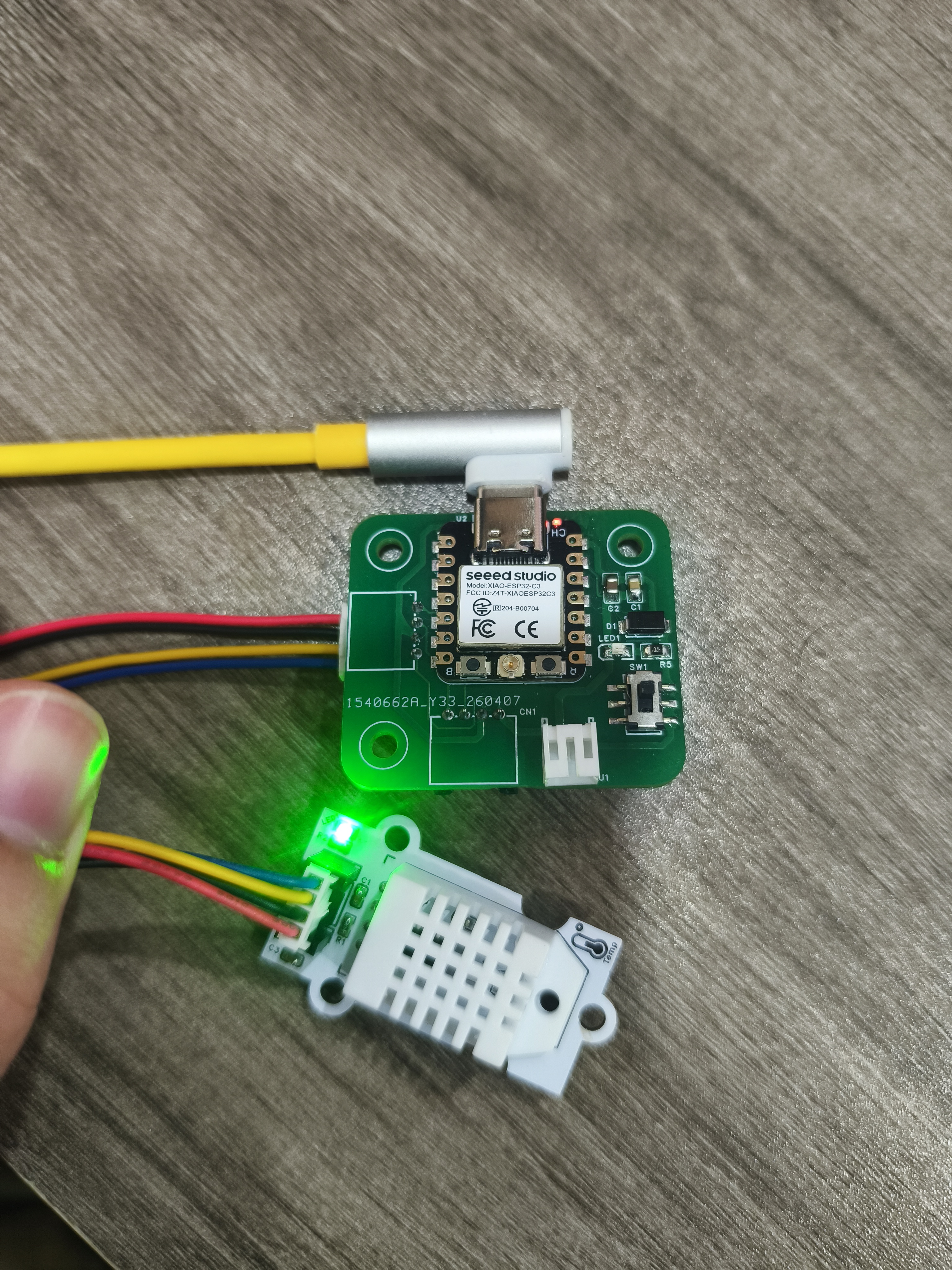
After power is turned on, the module indicator lights up, indicating that the sensor is powered normally. After the hardware connection is completed, you can enter the program reading phase.
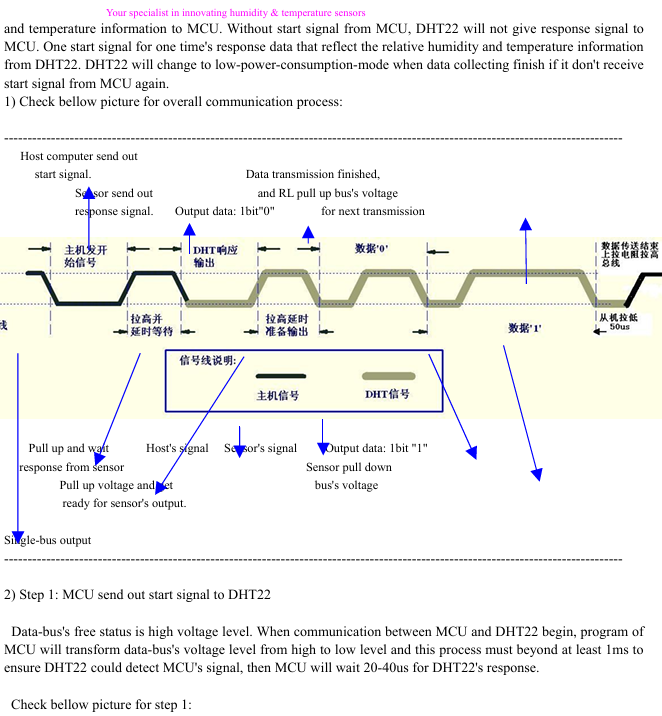
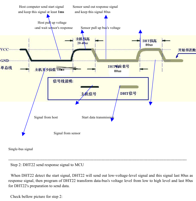
3. DHT22 Communication Principle
The DHT22 is a digital temperature and humidity sensor that has already completed the measurement of humidity and temperature internally, and sends the results to the microcontroller via a single-wire digital signal. The microcontroller does not need to perform analog voltage conversion on its own, but only needs to read the data according to the protocol.
Its communication process is roughly as follows:
- The microcontroller sends a start signal to the DHT22.
- The DHT22 responds to the host's request.
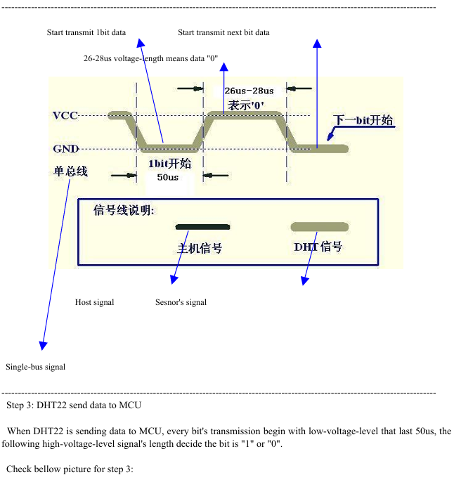
- The sensor sends temperature and humidity data at a fixed time sequence.
- The single-chip microcomputer parses the data and calculates whether the checksum is correct.
Since the communication timing of DHT22 is relatively strict and writing low-level drivers manually is rather troublesome, this time we directly use the dht library provided by MicroPython for reading.
4. Program Writing and Programming
This program runs in the MicroPython environment. The program first imports machine.Pin, time, and dht modules, then creates a DHT22 object, reads temperature and humidity in a loop, and prints them via REPL.
# Python env   : MicroPython v1.23.0
# -*- coding: utf-8 -*-
# @Time    : 2025/9/1 上午11:22
# @Author  : ben0i0d
# @File    : main.py
# @Description : dht22驱动测试文件 测试输出温湿度

# ======================================== 导入相关模块 =========================================

from machine import Pin
import time
import dht

# ======================================== 全局变量 ============================================

# ======================================== 功能函数 ============================================

# ======================================== 自定义类 ============================================

# ======================================== 初始化配置 ===========================================

# 延时等待设备初始化
time.sleep(3)
# 打印调试信息
print("FreakStudio : Using OneWire to read DHT22 sensor")

# 延时1s,等待DHT22传感器上电完成
time.sleep(1)
# 假设数据脚接 GPIO6
d = dht.DHT22(Pin(6))

# ========================================  主程序  ============================================

while True:
    try:
        d.measure()
        temp = d.temperature()
        hum = d.humidity()
        print("Temperature: %.1f C  Humidity: %.1f %%" % (temp, hum))
    except Exception as e:
        print("Read error:", e)
    time.sleep(2)
In the code, d.measure() is used to trigger sensor measurement, d.temperature() reads the temperature, d.humidity() reads the humidity. A 2-second delay is set between each reading because the sampling speed of the DHT22 cannot be too fast, and frequent readings are prone to errors.
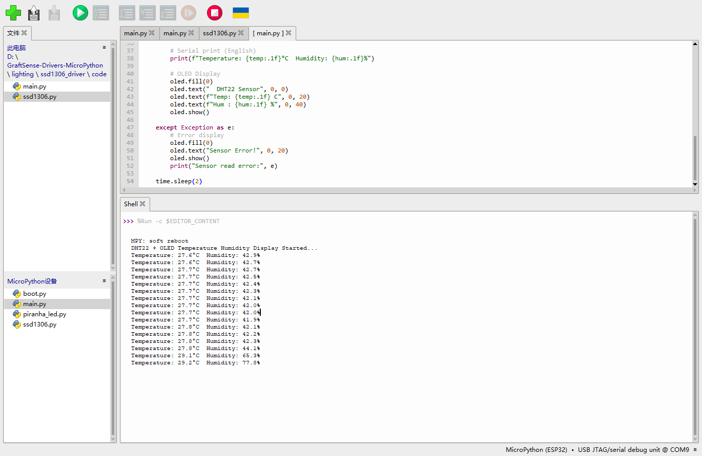
The development board successfully reads DHT22 data and prints the temperature and humidity in the REPL, indicating that both the hardware connection and program reading are working properly.
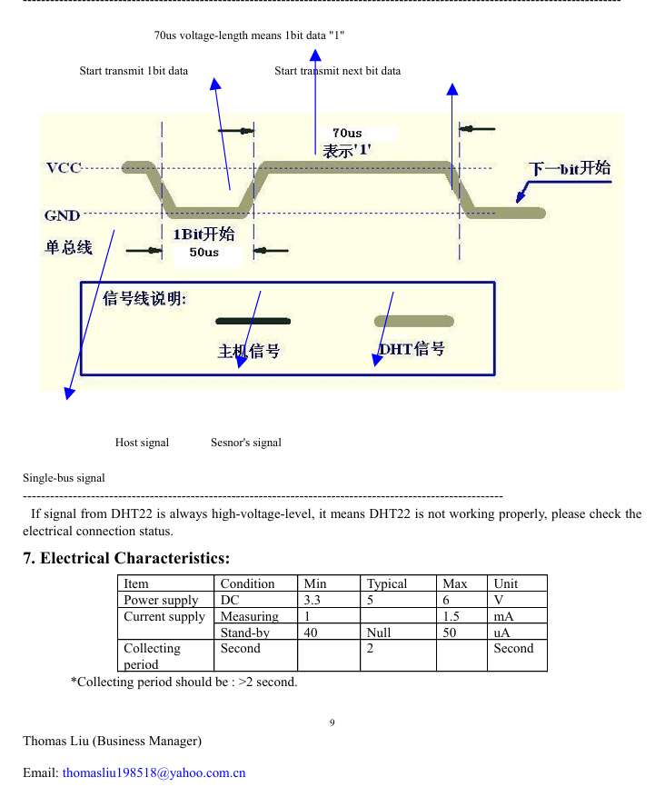
5. Sensor Performance Parameters
The main performance parameters of DHT22 are as follows:
| Humidity | Temperature | |
|---|---|---|
| Resolution | 0.1 %RH | 0.1 ℃ |
| Measuring Range | 0 ~ 99.9 %RH | -40 ~ 80 ℃ |
| Accuracy | ±2 %RH (at 25℃) | ±0.5 ℃ |
| Recommended Storage Conditions | ≤ 60% RH | 10℃ ~ 40℃ |
| Operating Voltage | \multicolumn{2}{c}{3.3V ~ 5V} |
According to the common specifications of the DHT22, its temperature measurement range is approximately -40°C to 80°C, with a temperature accuracy typically ±0.5°C; the humidity measurement range is approximately 0-100%RH, with a humidity accuracy typically ±2%RH to ±5%RH. Compared to the DHT11, the DHT22 has a wider measurement range and higher accuracy, making it more suitable for environmental monitoring projects.
6. Measurement Accuracy Verification
To verify whether the sensor readings are reasonable, I continuously read multiple sets of temperature and humidity data and observed whether the readings were stable. Since no calibrated professional temperature and humidity meter was used for comparison this time, the main focus here is on stability verification rather than strict laboratory calibration.
Test Method:
- Place the DHT22 in a stable indoor environment.
- Read data once every 2 seconds.
- Observe whether there are obvious jumps in the temperature and humidity readings.
- Roughly compare with indoor perceived temperature and environmental humidity.
The recording method is as follows:
| Number of times | Temperature (°C) | Humidity (%RH) | Observation |
|---|---|---|---|
| 1 | Room temperature reading | Environmental humidity reading | Reading is normal |
| 2 | Smaller change | Smaller change | Stable |
| 3 | Smaller change | Smaller change | Stable |
From the REPL output results, it can be seen that the sensor can continuously return temperature and humidity data without frequent occurrences of Read error. In an indoor environment, the temperature readings change little, and the humidity does not fluctuate significantly, indicating that the sensor reading process is basically stable.
If more rigorous accuracy verification is required in the future, a calibrated thermo-hygrometer can be used as a reference value, and then the error between the DHT22 reading and the reference instrument can be calculated. For example:
Error = DHT22 Reading - Reference Instrument Reading
This way, a more accurate deviation range can be obtained, and it can be determined whether the sensor meets the project requirements.
7. Design Documents and Bill of Material
The source files of the development board used this week come from the self-made development board files of the previous Electronic Design / Electronic Product Production Week.
The Bill of Material for input device-related items is as follows:
| Name | Quantity | Description |
|---|---|---|
| DHT22 Temperature and Humidity Sensor Module | 1 | Input device, used for collecting temperature and humidity |
| Independently Produce ESP32-C3 / XIAO-C3 Development Board | 1 | Main Control and Interface Expansion |
| Connecting Line | Several | Connect VCC, GND, DIO |
| MicroPython Firmware | 1 | Run the reading program |
8. Summary
Through this week's assignment, I completed the basic process from the hardware connection of input devices to program reading. In the group assignment, we observed the digital signals of the key module through an oscilloscope and understood concepts such as high and low levels, rising edges, falling edges, and voltage cycles; in the individual assignment, I used the DHT22 temperature and humidity sensor to implement Data Acquisition and printed the results via MicroPython.
This exercise has made me realize that the key to input devices is not only "connecting the wires" but also understanding the type of signals they output. If it's a button, attention should be paid to high and low levels and jitter; if it's an analog sensor, an ADC should be used; if it's a digital sensor like DHT22, attention should be paid to communication timing and reading frequency. Only by understanding the signals themselves can sensor data be used more stably in subsequent practical projects.
Attachment
ProPrj_GraftPort-XIAO扩展板_2026-03-14.epro2
BOM_Board1_PCB1_2026-06-09.xlsx
AI Assistance:
During the preparation of this documentation, ChatGPT (GPT-4) was used as a language assistance tool.
It helped with sentence polishing and translation from Chinese to English to improve readability and clarity.