Week 5 - 3D Scanning and Printing
During this week, we started learning about 3D Scanning and Printing (3D Scanning and Printing). These two technologies are very important components in digital manufacturing. 3D printing belongs to Additive Manufacturing (Additive Manufacturing), which forms three-dimensional structures by stacking materials layer by layer, thus enabling the production of some complex structures that are difficult to achieve with traditional subtractive manufacturing methods, such as CNC machining, for example, enclosed spaces, internal structures, or complex shapes.In contrast, 3D scanning is a method of acquiring three-dimensional data from the real world, which converts the surface of an object into an editable 3D model by photographing or scanning it.
Group assignment:
The group assignment mainly involves understanding different types of 3D printing technologies and equipment, such as FDM, SLA, etc., and observing and testing the basic workflow of the printer. At the same time, understand the impact of parameters such as printing materials, layer thickness, and support structures on the printing results, and familiarize yourself with the printing process through simple tests.
Individual assignment:
Individual assignments mainly consist of two parts. The first part is to design a 3D model that cannot be completed through subtractive manufacturing, such as an object with enclosed spaces or internal structures, and complete the modeling and 3D printing while documenting the design and production process. The second part is to perform 3D scanning on a real-world object, select appropriate objects and scanning software, generate a 3D model through shooting or scanning, and document the scanning and post-processing procedures.
Overall, the focus of this week is to understand the differences between 3D printing and traditional manufacturing methods, learn how to design structures suitable for additive manufacturing, and at the same time, gain a preliminary understanding of the basic methods of 3D scanning to obtain 3D models. Through these exercises, we can better understand the conversion process between digital models and physical objects, laying a foundation for subsequent digital manufacturing projects.
Team Assignment
Group Assignment Page: https://fabacademy.org/2026/labs/chaihuo/docs/week5/week5_group_assignment
1. Equipment Introduction
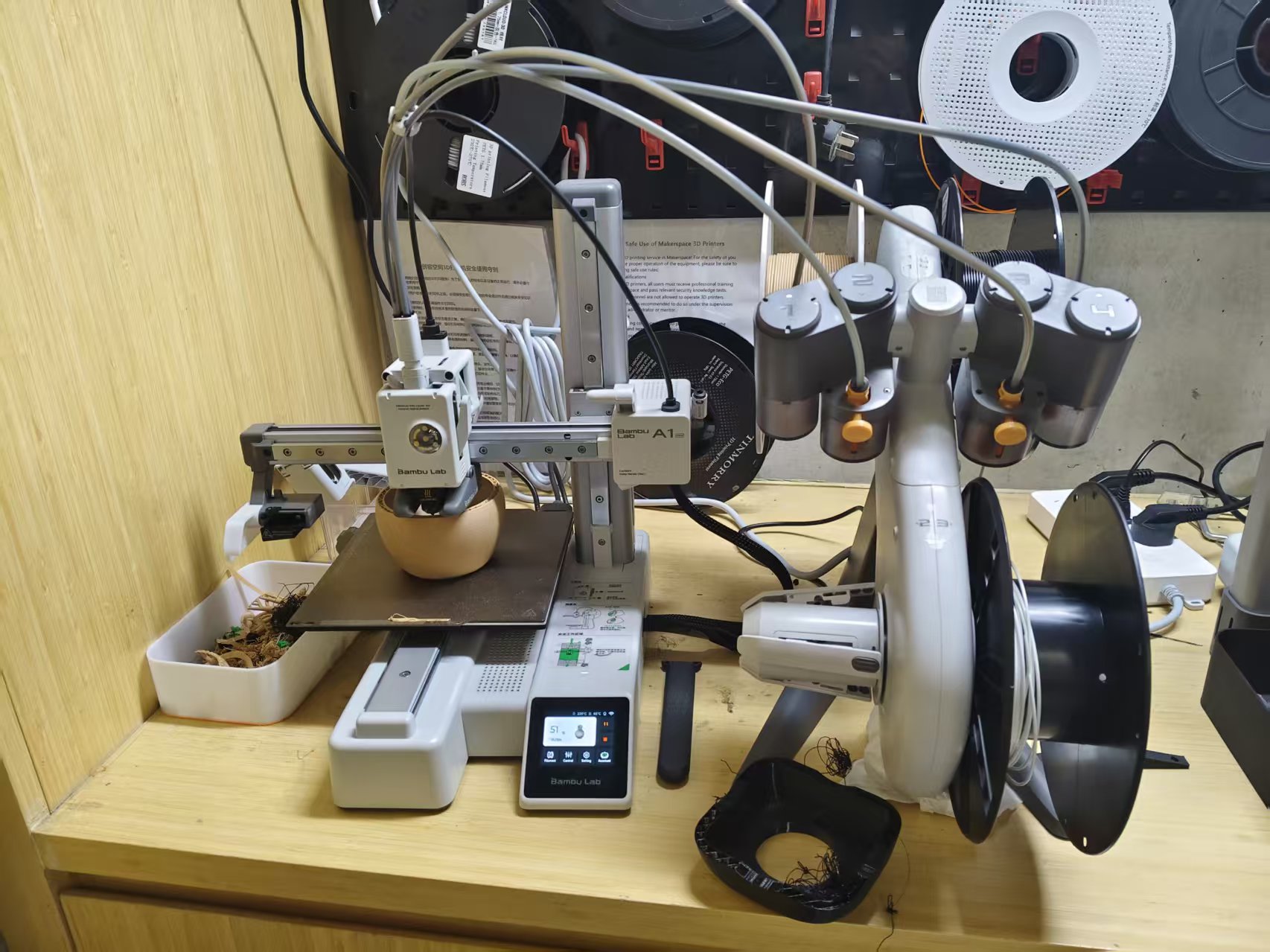
This group assignment mainly involved understanding and testing the two existing types of 3D printing equipment in the Maker Space: FDM (Fused Deposition Modeling) and SLA (Stereolithography) .
FDM printers are the most common desktop 3D printing devices, which melt consumables (usually PLA or ABS) through a heated nozzle and then deposit them layer by layer to form objects. Their advantages include low consumable costs, simple operation, and suitability for printing models with increased dimensions; the disadvantages are obvious layer lines and relatively low surface accuracy.
Chaihuo Maker Space is equipped with a Bambu Lab A1 Mini 3D printer and an Automatic Material System (AMS) Lite.
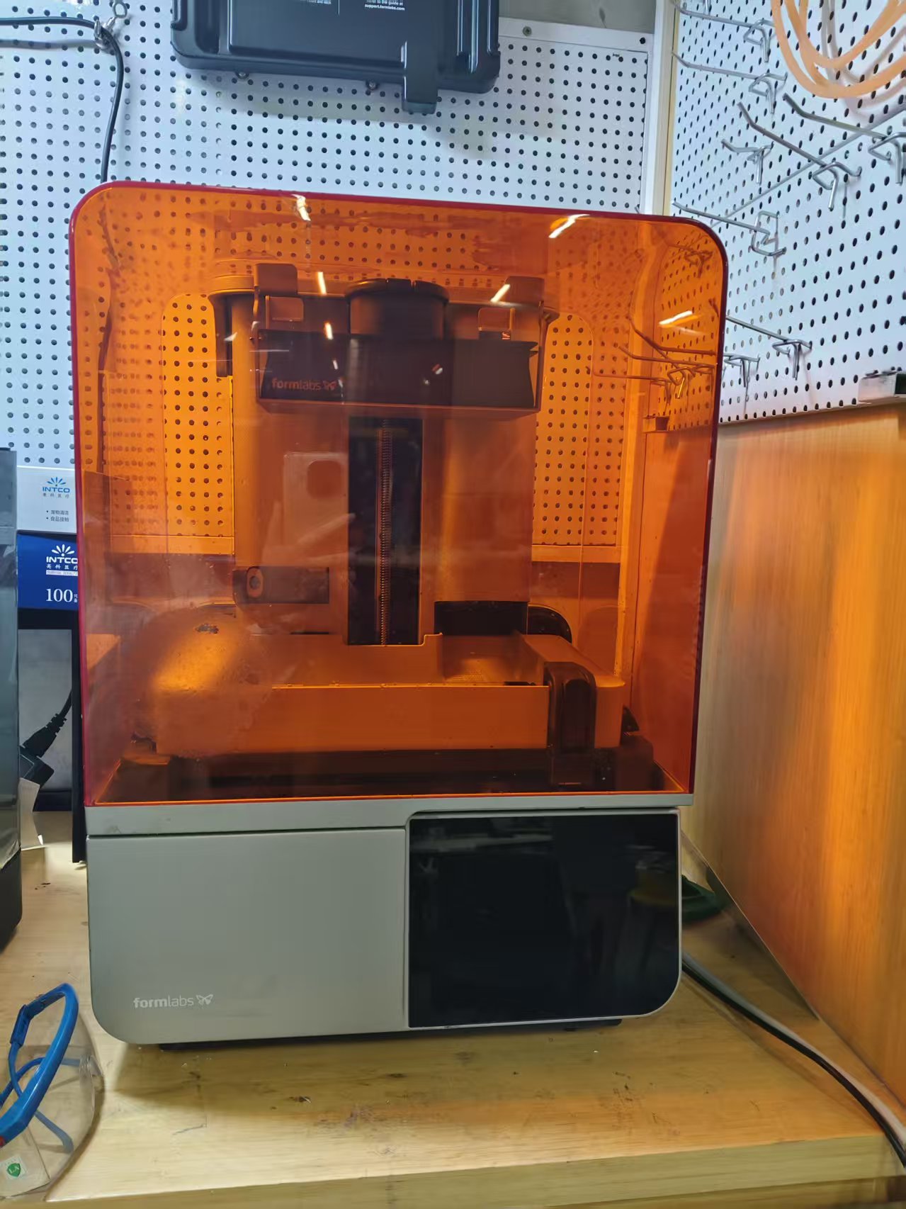
SLA printers create layer-by-layer models by absorbing photosensitive resin with ultraviolet light. Compared to FDM, SLA offers higher printing precision and smoother surfaces, making it suitable for models with higher requirements; however, the cost of consumable materials (resin) is higher, and post-processing steps are more complex, requiring cleaning with alcohol and secondary detail curing.
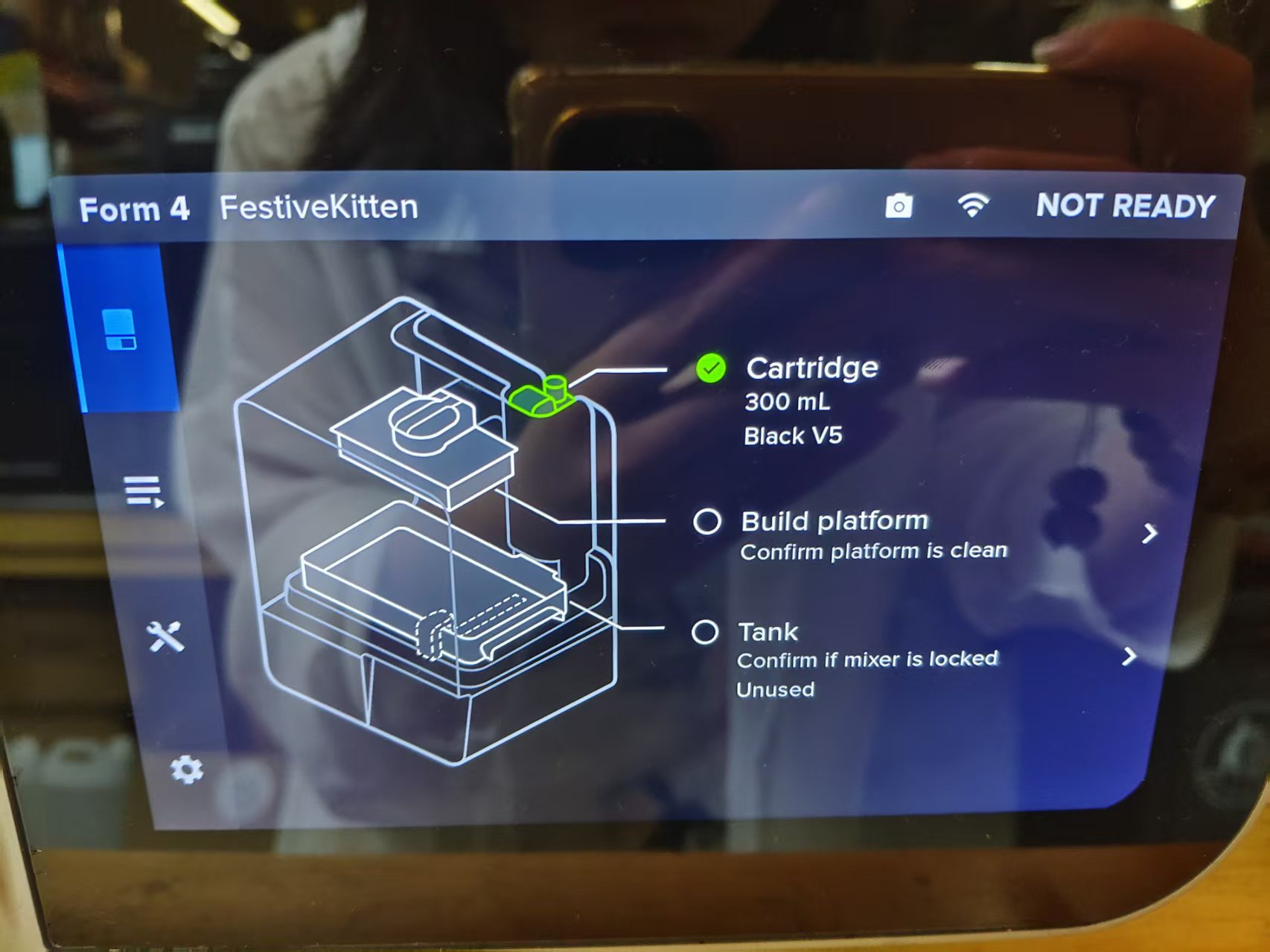
Chaihuo Maker Space is equipped with a Formlabs Form4 SLA 3D printer.
The comparison of the main parameters of the two devices is as follows:
| Parameter | Frequency Band | Service Level Agreement |
|---|---|---|
| Formation Principle | Bracket | Light curing |
| Common Materials | PLA、ABS、PETG | Photosensitive Resin |
| Layer Thickness Range | 0.1–0.3 mm | 0.025–0.1 mm |
| Surface Quality | Generally, layer striations are visible | High, smooth surface |
| Support Structure | Needs | Needs |
| Post-processing | Just rely on it | Needs cleaning + secondary curing |
| Applicable Scenarios | Functional parts, large-size models | Precise Model, Positioning Parts |
2. Influence of Key Parameters
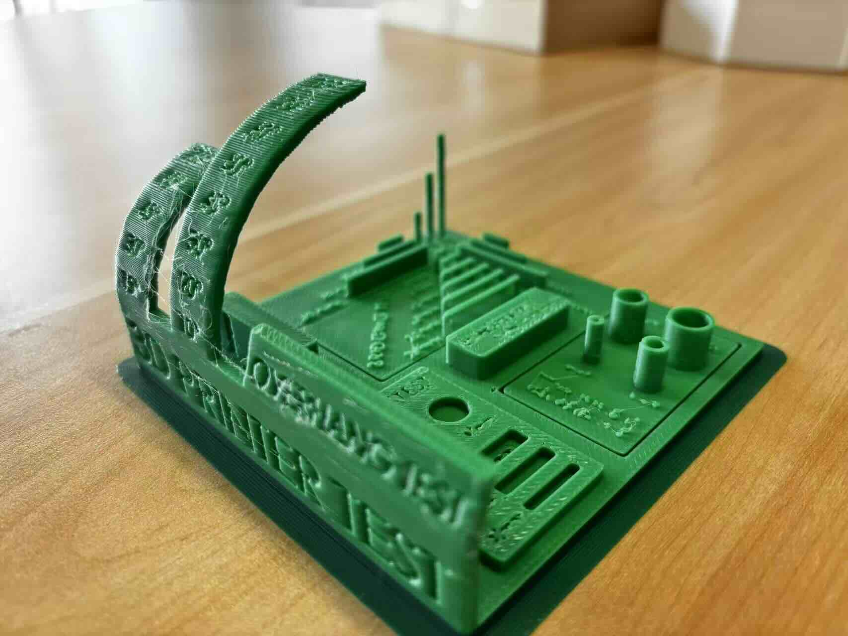
We conducted five comprehensive design rule tests to evaluate the printing capabilities of the A1 Mini.
2.1 Angle Test
Objective: To test the minimum angle at which the printer can print normally without support.
Result:
| Angle | Print Quality |
|---|---|
| 90° ~ 20° | ✅ Good print, clean surface |
| 10° | ❌ Failed, with "stringing/noodles" phenomenon occurring |
| 0° | ❌ Failed, severe wire drawing |
Conclusion: Without support, the minimum printable angle is 20°, and support structures need to be added below this angle.
2.2 Bridging Test
Objective: To test the maximum bridging span that the printer can stably print under unsupported conditions.
Results: All bridging within the range of 2mm to 20mm was successfully printed, with no stringing or sagging, and the structure is strong.
Conclusion: The bridging performance of A1 Mini is excellent, and bridging within 20mm can be completed without support.
2.3 Clearance Test
Objective: Determine the minimum functional clearance required for moving parts.
Result:
| Gap | Result |
|---|---|
| 0.1 mm | ❌ Completely immobile |
| 0.2 mm | ❌ Completely immobile |
| 0.3 mm | ⚠️ Can only move half the distance |
| 0.4 mm ~ 1 mm | ✅ Can move freely along the track |
Conclusion: The minimum recommended clearance for moving parts is 0.4 mm (exactly equal to the nozzle diameter). This test is also our first attempt to use a tree-like support structure.
2.4 Wall Thickness Test
Objective: Determine the minimum printable wall thickness that ensures structural strength.
Result:
| Wall Thickness | Result |
|---|---|
| 0.1 mm | ❌ Unable to print |
| 0.2 mm | ❌ Unable to print |
| 0.3 mm | ❌ Unable to print |
| 0.4 mm | ✅ Minimum printable thickness |
Conclusion: Wall thickness must be ≥ nozzle diameter (0.4 mm) for successful printing; below this value, the printer cannot extrude and form properly.
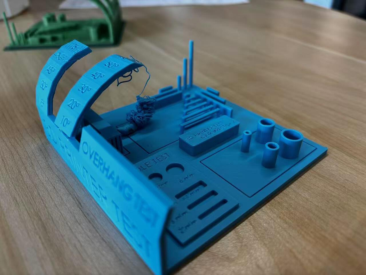
2.5 Overhang Test
Objective: Evaluate the printing quality under different overhang lengths.
Result:
| Overhang length | Quality Assessment |
|---|---|
| 1 mm | ✅ Surface clean, good effect |
| 2 mm ~ 5 mm | ⚠️ Slightly rough surface, minor blemishes |
| 6 mm ~ 10 mm | ❌ Severe stringing, "noodle" phenomenon is obvious |
Conclusion: The best effect is within 1 mm of overhang; acceptable within 5 mm ; more than 6 mm need to add support.
3. Summary of Design Rules
| Parameter | Recommended Limit | Threshold |
|---|---|---|
| Minimum Printing Angle | 20° | 10° (Start Failure) |
| Maximum unsupported bridging | 20 mm | Tested upper limit |
| Minimum clearance of moving parts | 0.4 mm | 0.3 mm (only partially movable) |
| Minimum Wall Thickness | 0.4 mm | < 0.4 mm (unprintable) |
| Maximum unsupported overhang | 1 mm (optimal) / 5 mm (acceptable) | ≥ 6 mm (obvious failure) |
Through the printing experiment of the integrated test model, we have gained an intuitive understanding of the performance boundaries of the Bambu Lab A1 Mini:
- Nozzle diameter is a core parameter : A nozzle diameter of 0.4 mm directly determines the lower limits of the minimum wall thickness and minimum clearance, which must be used as a reference during design.
- Excellent bridging performance : Without any support, the bridging print quality within 20 mm is very ideal, which is very helpful for saving support materials and post-processing time.
- Caution is needed for overhang and angle : Small angles (< 20°) and long overhangs (> 5 mm) are the areas most prone to filament failure, which should be avoided as much as possible in actual design, or support should be planned in advance.
- Tolerance design allows for a margin : For moving mating parts, it is recommended that the clearance be set to 0.4 mm or more, with 0.5 mm being a safer design margin.
The performance of each printer varies due to differences in model, settings, and consumables. In actual projects, the target printer should first be tested and calibrated before formal design is carried out.
Individual Assignment
1. A beautiful vase
For this individual assignment, I chose to design a vase as the 3D printing object. The changing contour of the vase's waist cannot be directly achieved through subtractive manufacturing (such as CNC machining), making it suitable as a practice object for additive manufacturing.
The design concept is to create geometric shapes with different diameters on planes at different heights, and then use the Loft command to connect these axes into smooth curved solid bodies, forming a vase shape with varying arcs.
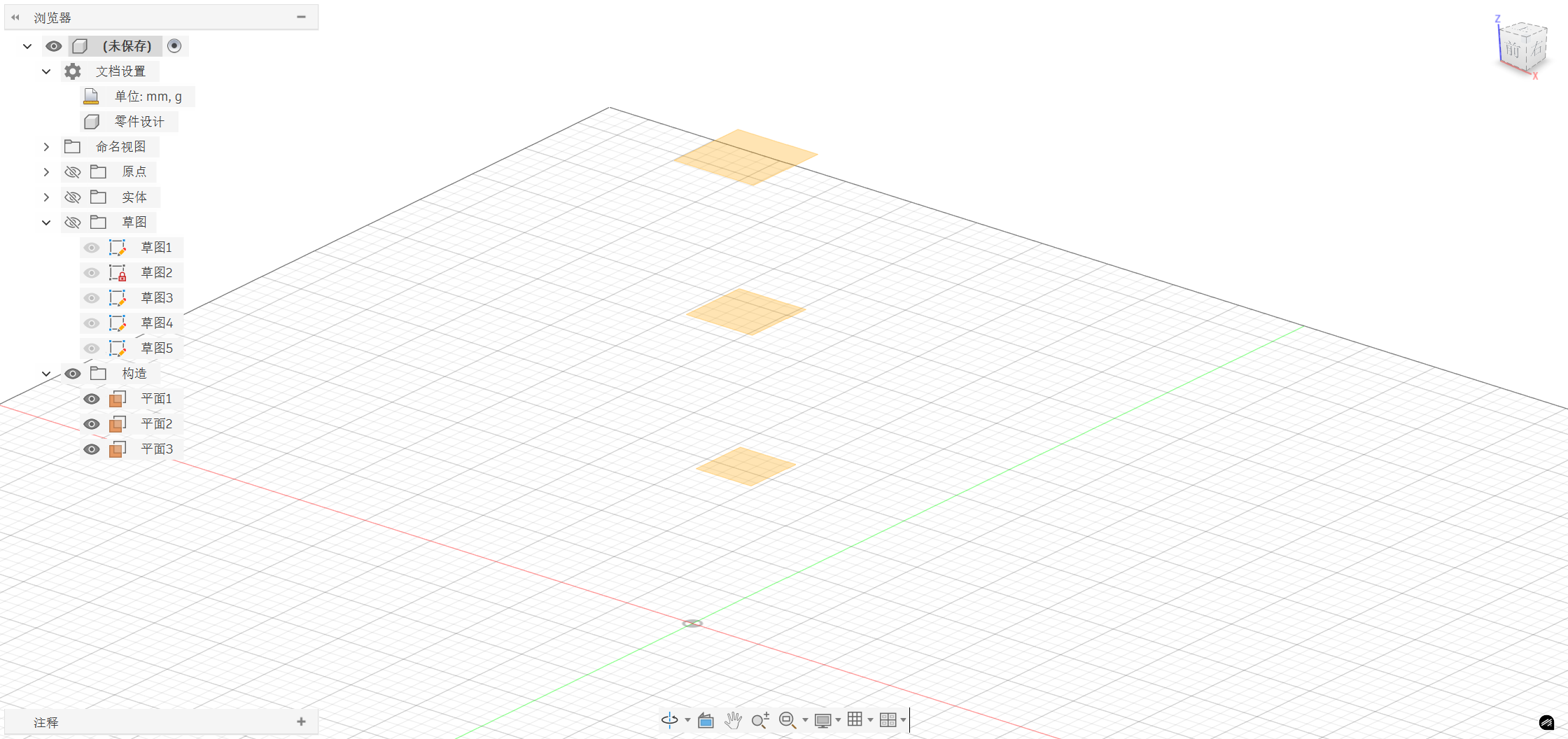
Step 1: Construct a reference plane
In Fusion 360, based on the XY plane, construct a new offset plane upward every 50 mm. Since the XY plane itself already exists, we only need to construct a total of 3 planes:
| Plane Number | XY Plane Height |
|---|---|
| Plane 1 | 0 mm (XY plane) |
| Plane 2 | 50mm |
| Plane 3 | 100 millimeters |
| Plane 4 | 150mm |
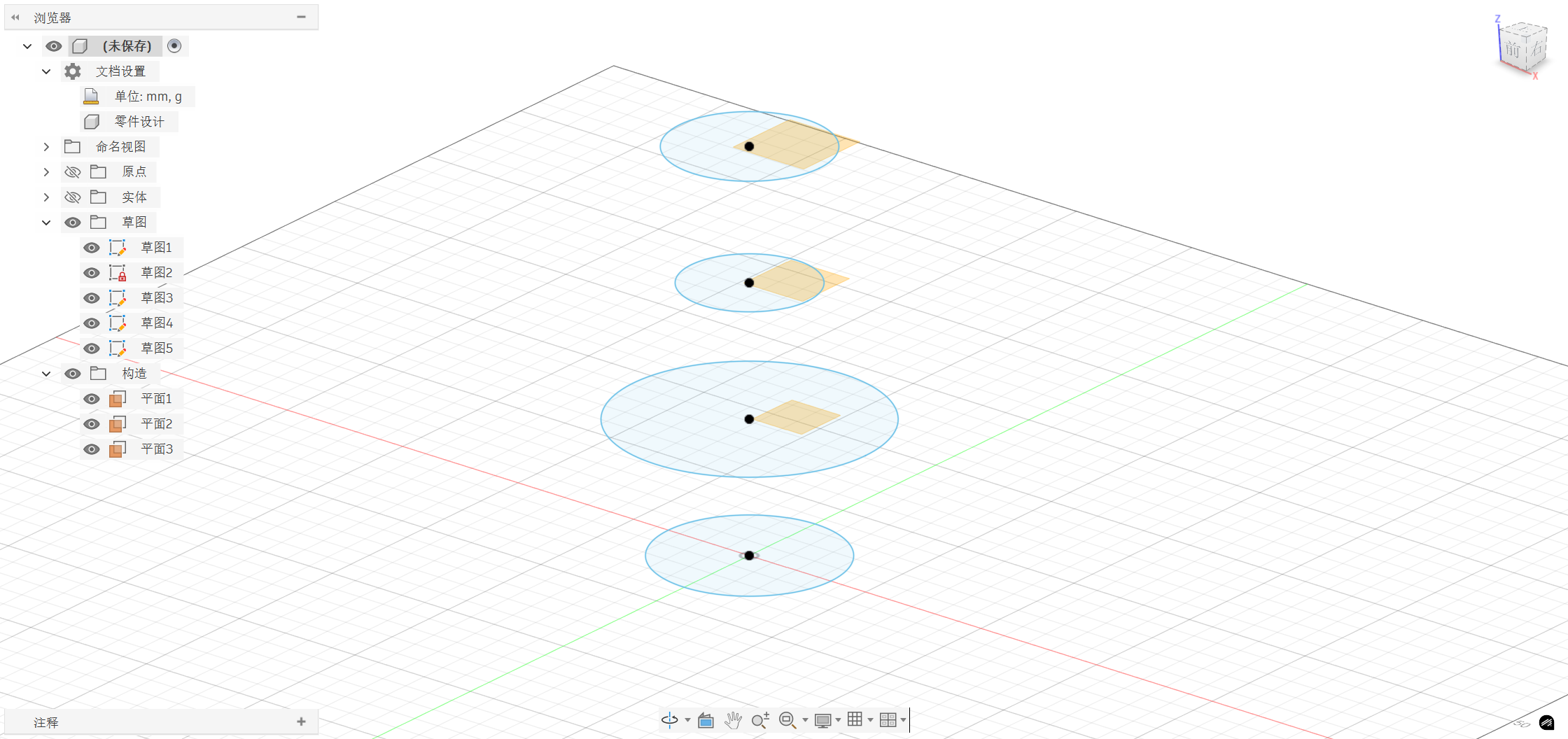
Step 2: Similar sketches on each plane
Create new sketches on 4 planes respectively, with the center of the circle as the center and the diameters as follows:
| Plane | Circular diameter dimension |
|---|---|
| Plane 1 (Bottom) | 70mm |
| Plane 2 | 100 millimeters |
| Plane 3 (Waist) | 50mm |
| Plane 4 (Top) | 60mm |
Such a change in diameter gives the vase an oval shape with a wider bottom, a constricted middle, and a slightly flared top.
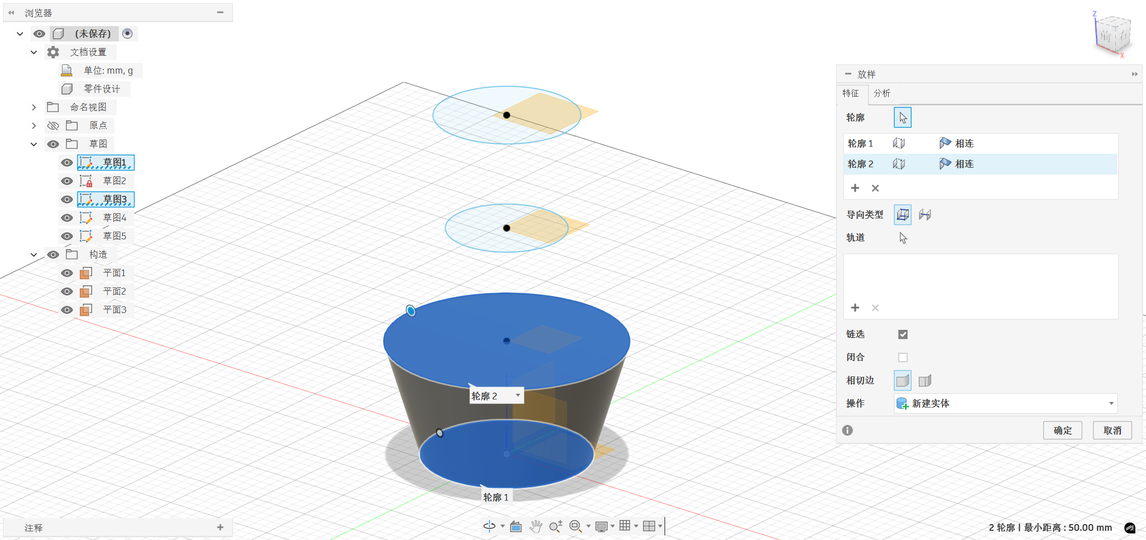
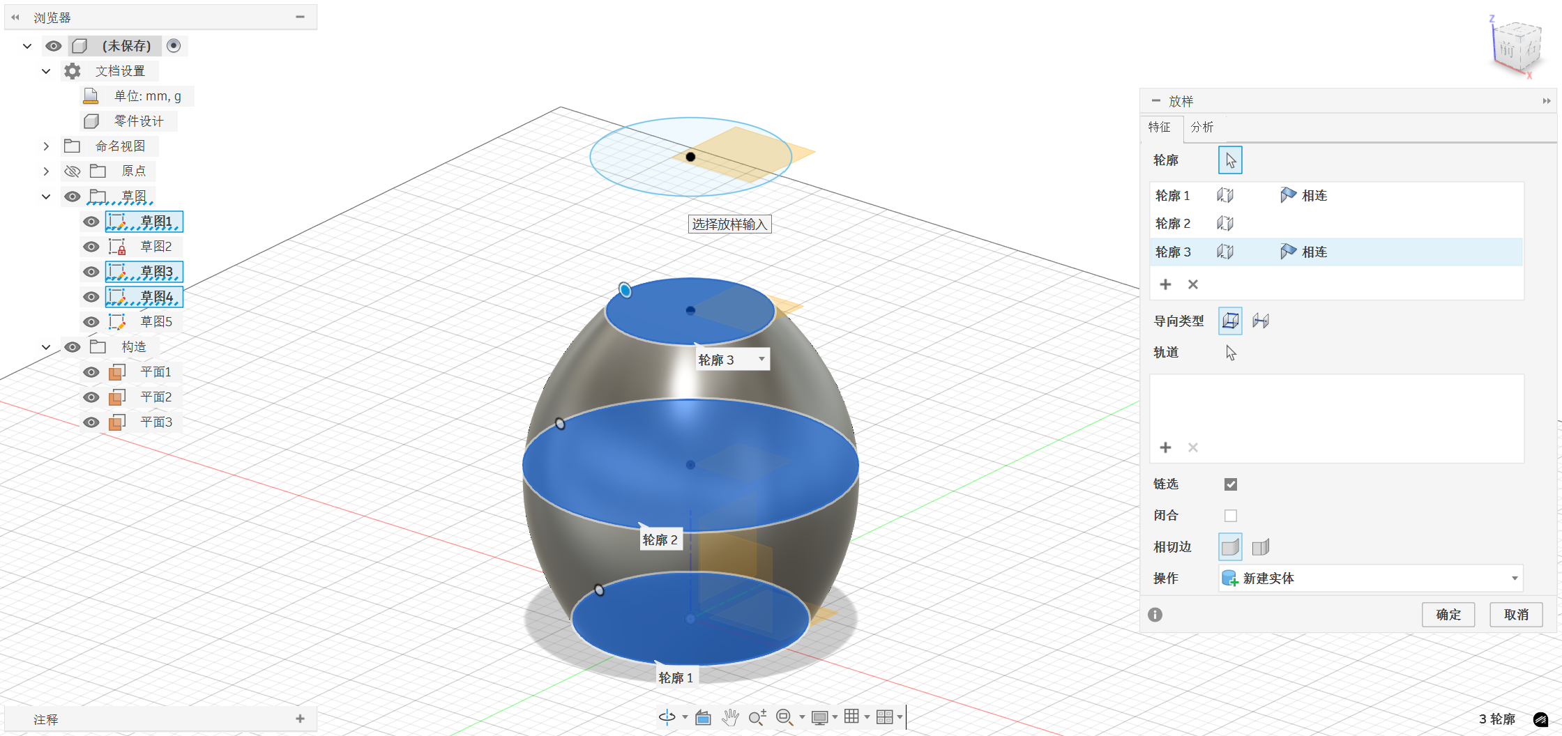
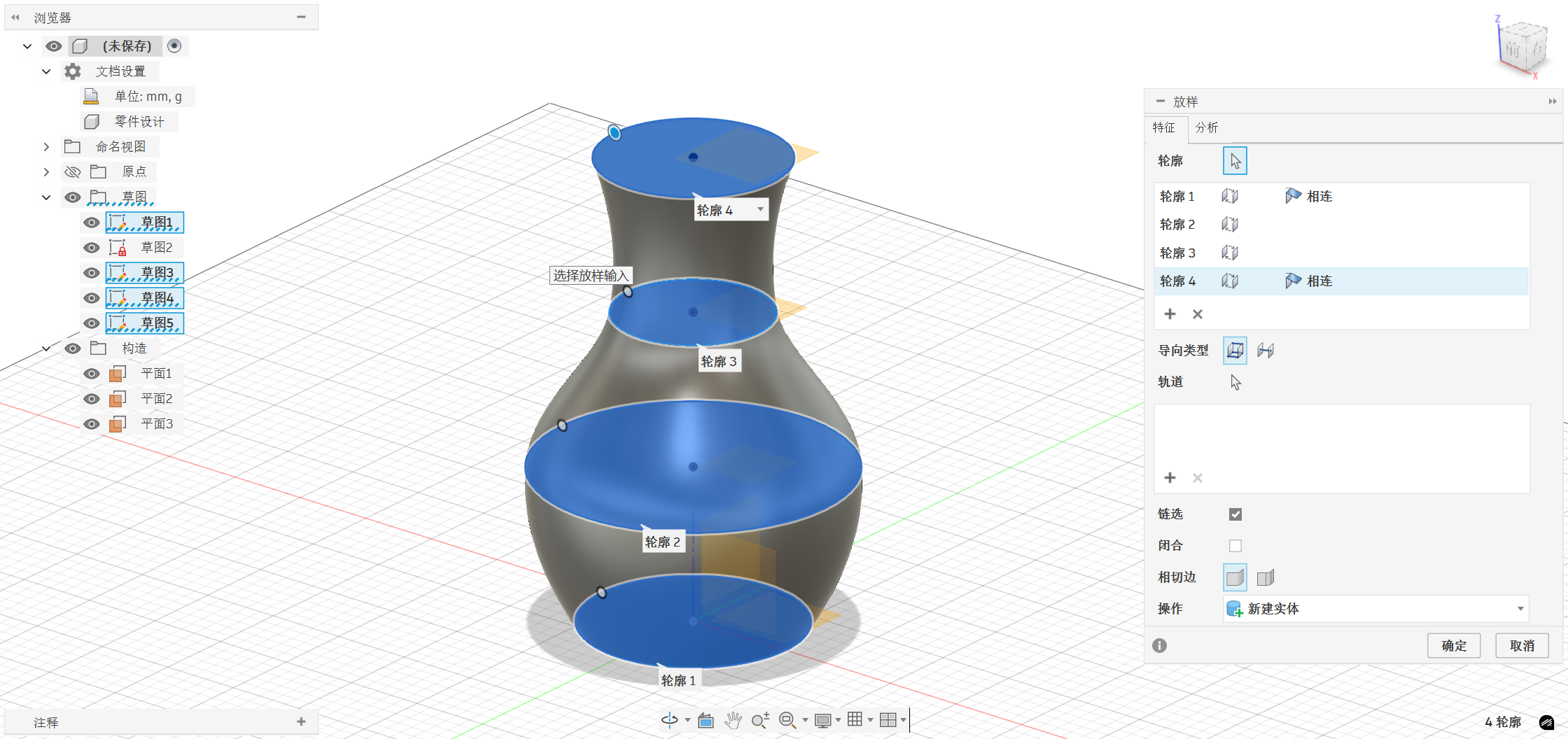
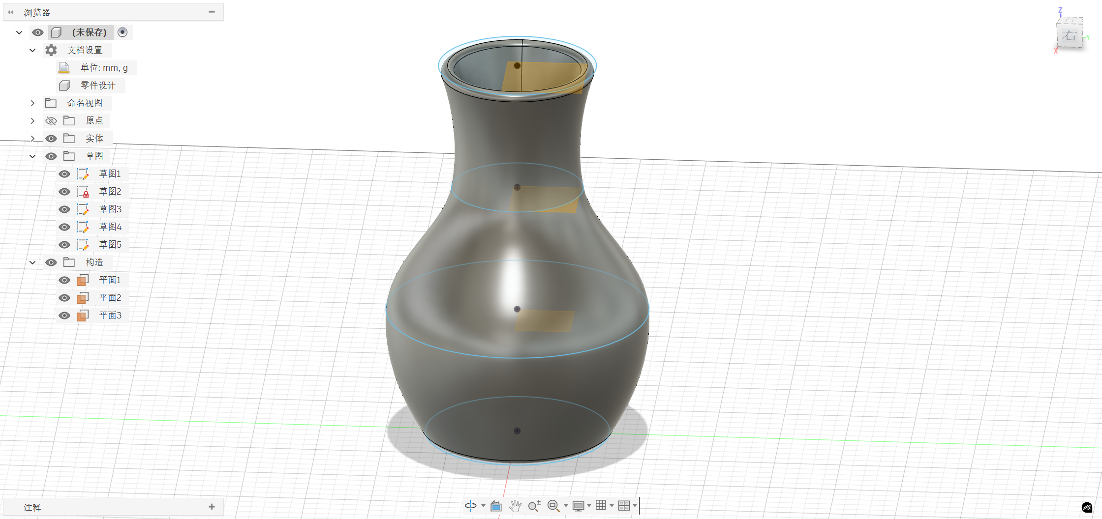
Step 3: Loft
SelectSamplingfrom the top menu, then click on 4 topological sketches in sequence from bottom to top, confirm generation, and Fusion 360 will automatically generate smooth transition curves between each waveform
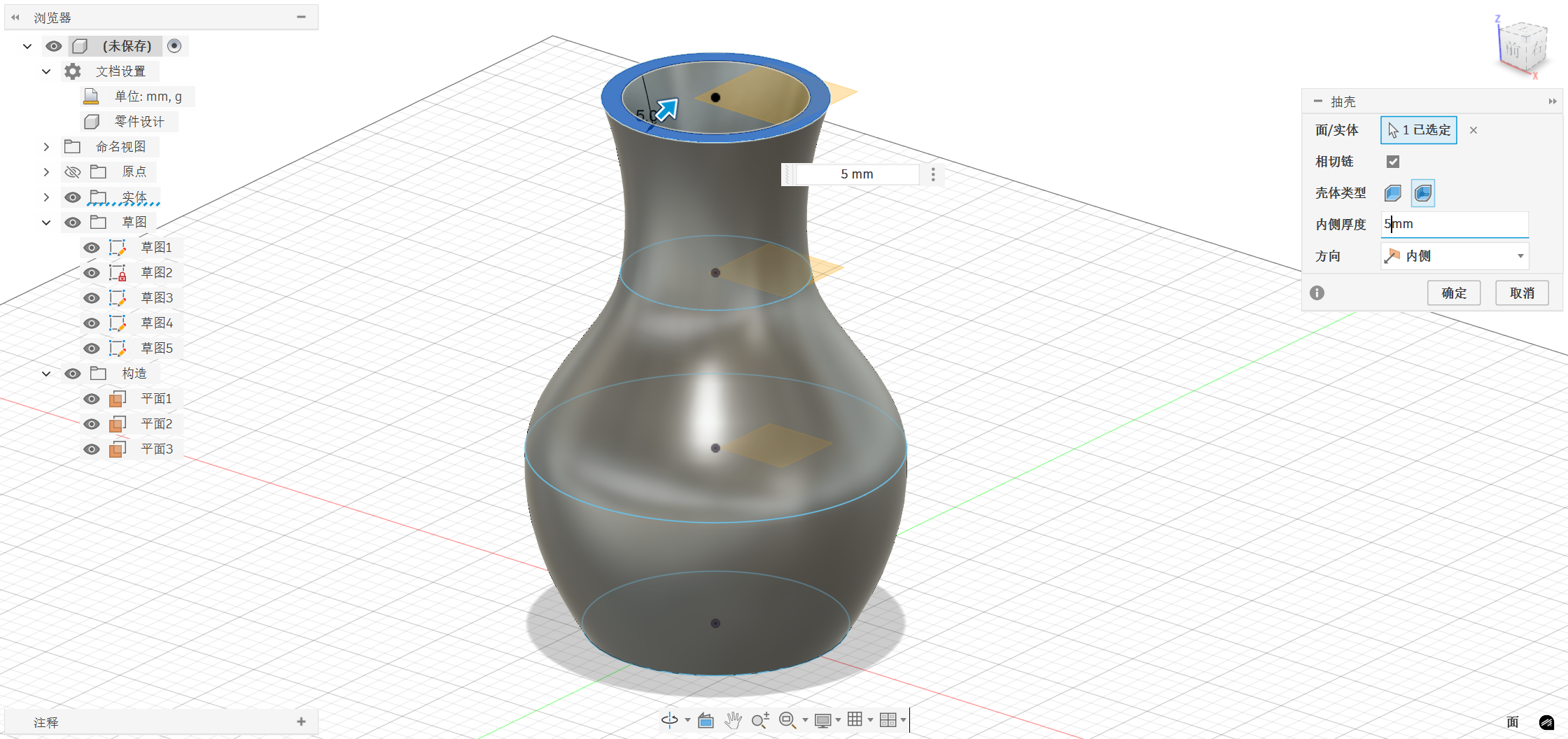
Step 4: Shell
After the vase entity is generated, it needs to be hollowed out internally to hold items:
SelectShellfrom the top menu, click on thetop of the vase,set the wall thickness to5mm,confirm, and the inside of the vase will be hollowed out, retaining a uniform wall thickness.
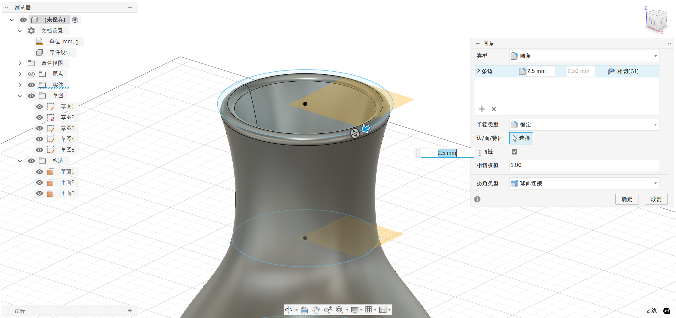
Step 5: Fillet
To make the bottom edge of the vase more rounded and less angular, width: selectrounded cornersfrom the top menu, select thetop and bottom edges of the vase,and set the rounded corner radius to2.5mm.
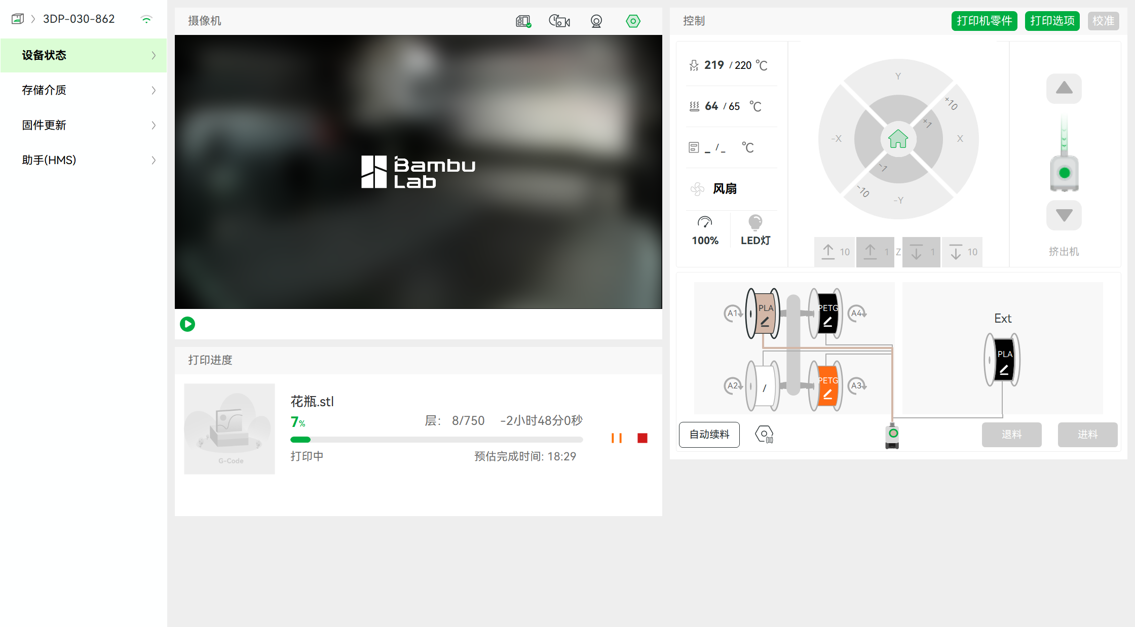
Step 6: Export and Print
After the modeling is completed, right-click on the entity and select "Export As" .stl format, then import it into slicing software to set printing parameters.
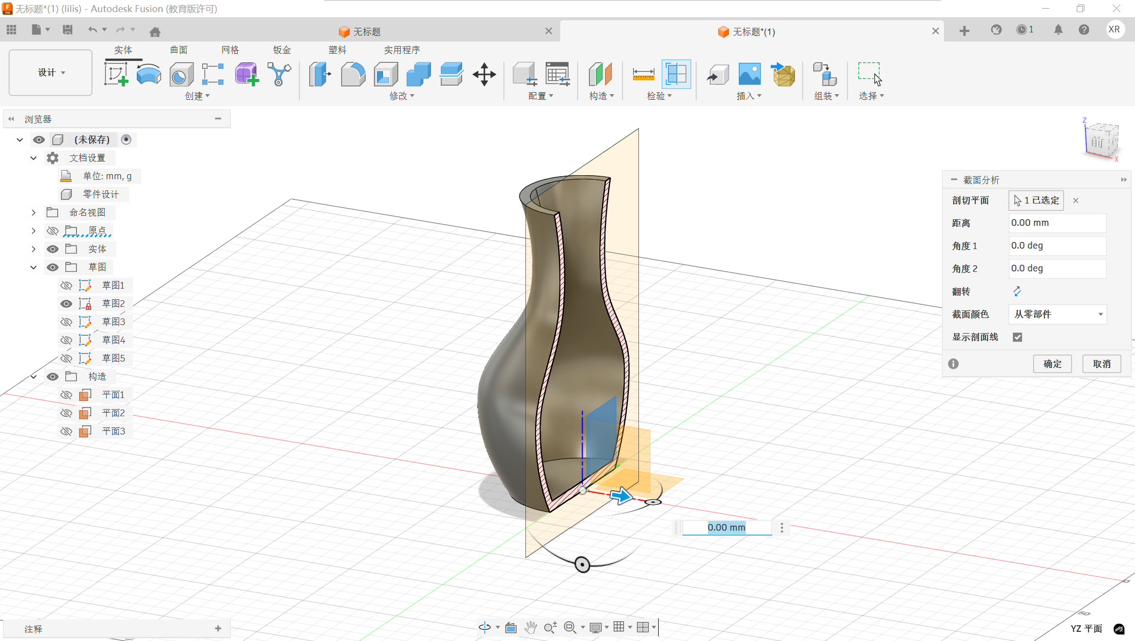
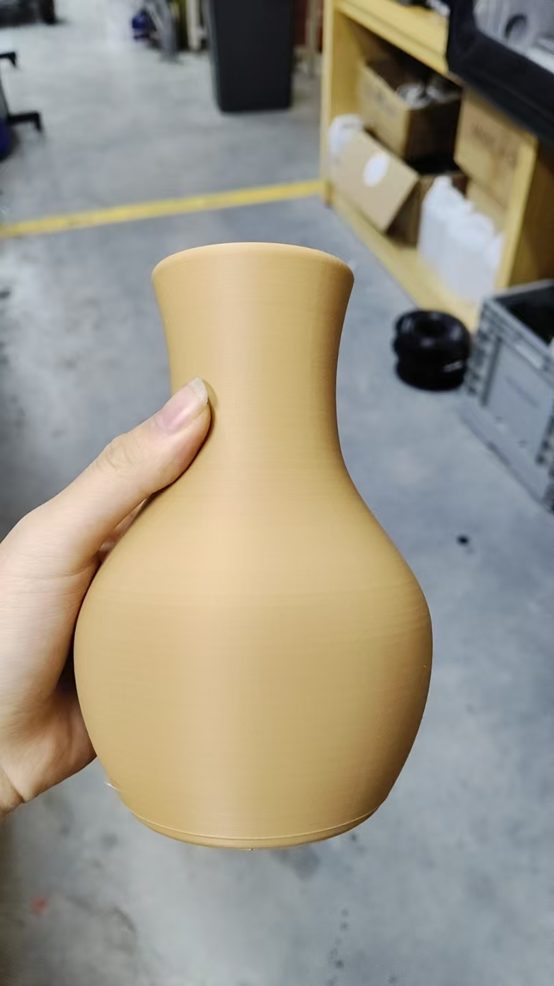
The software operation page is shown in the figure below:
After waiting for the printing to complete, the finished product is shown in the figure below:
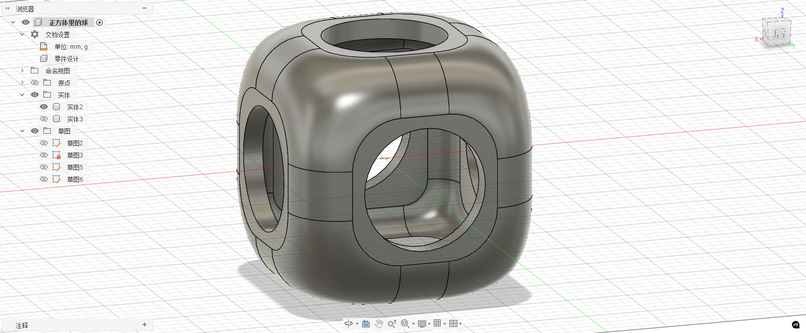
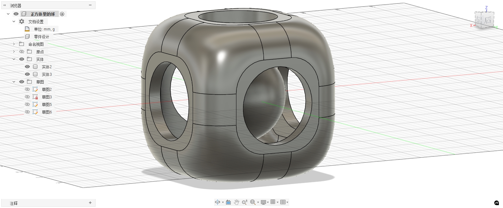
2. Ball in the square
In this assignment, I also designed a structure with a sphere embedded inside a cube. The exterior is a cube shell, and the interior contains a freely movable sphere. The characteristic of this structure is that there is an enclosed space inside, and the sphere is already enclosed within the structure after printing.
Note: This design has only completed the modeling and has not undergone actual 3D printing.
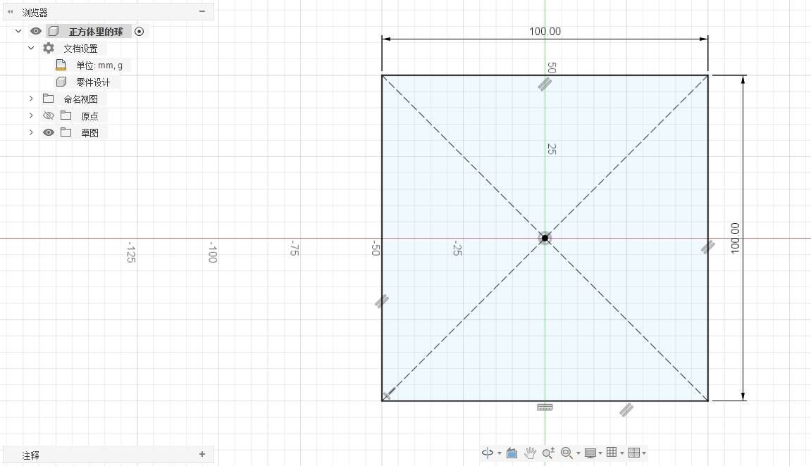
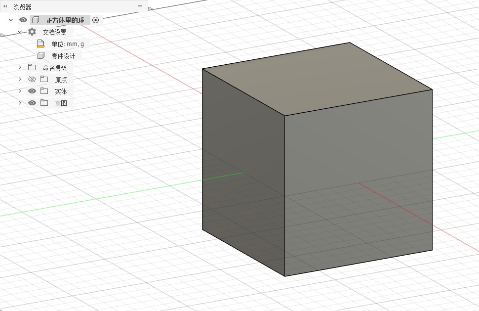
Step 1: Create an external cube
I have now drawn a 100mm x 100mm square in the sketch, and then extruded it 50mm upwards and downwards respectively to form a 100mm x 100mm x 100mm cube.
Step 2: Create an internal cavity
Return to the sketch editing, draw an 84mm×84mm square centered, which ensures a wall thickness of 8mm is retained around the perimeter.
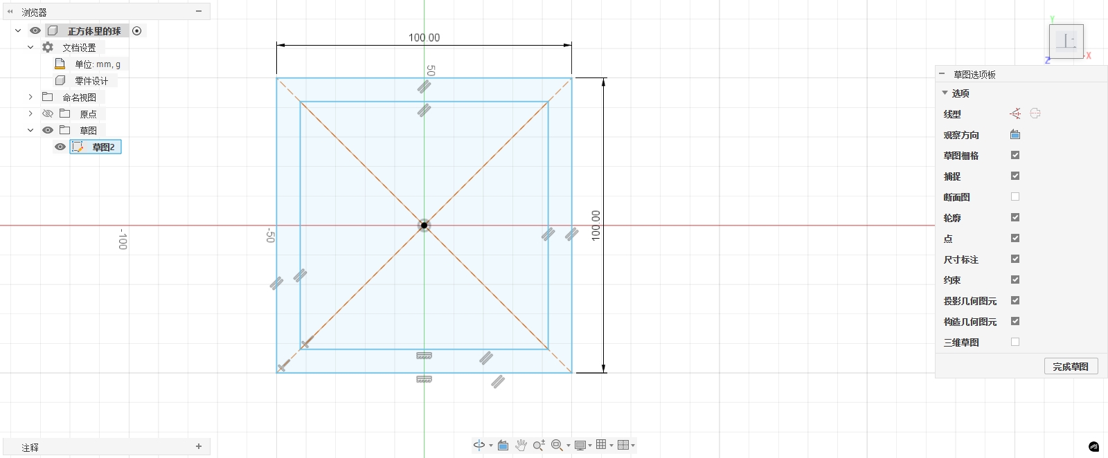
After completing the sketch, use the extrude function to cut this square downward, setting the depth to 84mm. This way, a regular cavity structure can be formed inside the cube while maintaining the stability of the external structure.
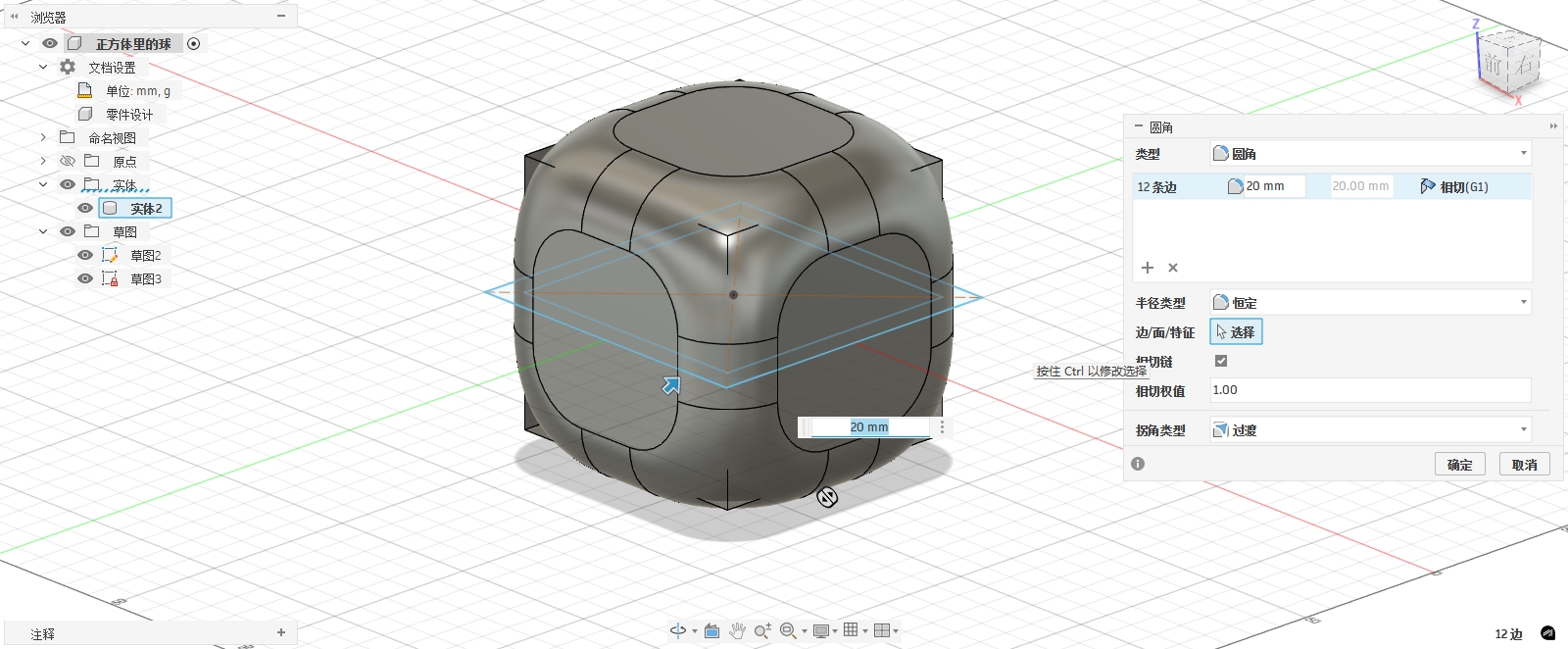
Step 3: Add rounded corners
I first rounded the outside of the cube with a radius of 20mm and set the corner type to transition, so that it has a smooth appearance and feels comfortable to hold.
Then, the internal cavity was also rounded with a radius of 10 mm, and the corner type was also a transition, allowing the ball inside to roll smoothly without getting stuck.
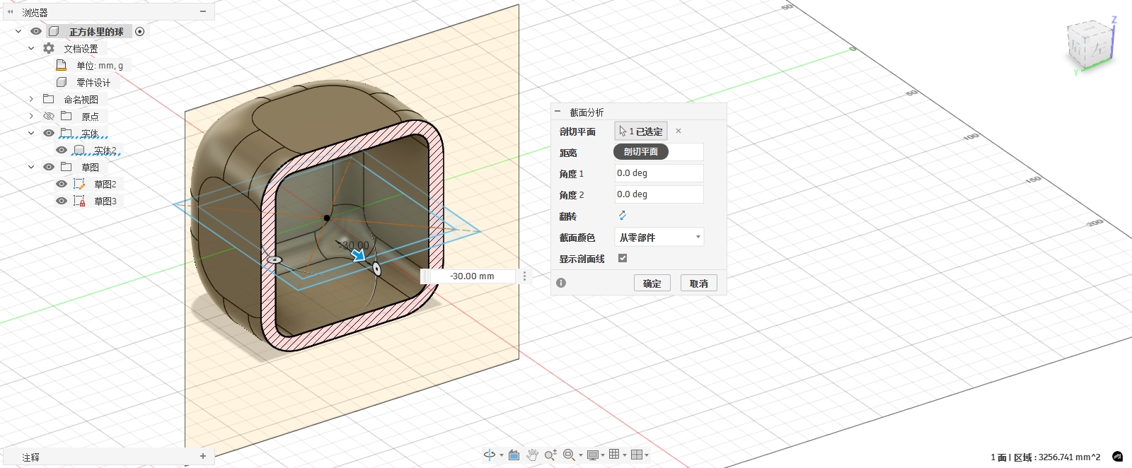
Step 4: Drill an inspection hole in the housing
To enable the subsequent internal sphere to be printed and also allow the movement of the sphere to be observed, I drilled holes in the outer shell.
Select a face of the cube, create a new sketch, and draw a circle with a diameter of 50mm at the center. Then use extrusion through the cube to form a circular hole.
Repeat this operation on the other faces to create holes on multiple faces of the box.
Step 5: Create an internal sphere
Create a new sphere in the middle of the cube with a diameter of 60mm.
3.3D model scanning
The second part of this week's personal assignment is to complete a 3D scan. I chose to use Luma AI for the scan because it does not require a dedicated structured light scanner. All it needs is to use a mobile phone to shoot videos or photos around the object, and then a 3D model can be generated through cloud computing. Compared with traditional handheld scanners, this method is more suitable for classroom exercises and easier to record the complete process.
The object of this scan is a bottle-shaped object placed on a table. It has relatively distinct outer contours, color textures, and surface details, such as the bottle body, bottle mouth, pump head, and the contact area with the table. The reason for choosing this object is that it is neither completely transparent nor a solid-colored smooth object, and its surface texture and edge features are relatively easy to be recognized by the software.
3.1 Luma AI Scanning Principle
Luma AI's scanning method belongs to image-based 3D reconstruction. Different from ordinary photography, the software does not simply save a two-dimensional image but infers the shape of an object in space through multi-angle photos or video frames.
The basic principle can be understood as the following steps:
- Collect multi-angle images: Shoot a full circle around the object to ensure that the same feature point appears in multiple photos.
- Identify image feature points: The software will search for features such as texture, edges, and color changes on the object's surface.
- Estimate Camera Position: Based on the positional changes of feature points in different photos, calculate the position and angle of the camera in space during shooting.
- Reconstructing 3D Space: Once the software knows the camera position and the correspondence of feature points, it can calculate the 3D shape of the object's surface.
- Generate point clouds, meshes, and textures: The final result can be displayed as a point cloud effect or exported as a textured OBJ mesh model.
Therefore, the quality of 3D scanning depends not only on the software but also on whether the software is provided with sufficiently stable, continuous, and overlapping image information during shooting. If the angle changes too much between photos or the object surface lacks texture, the software will have difficulty reconstructing correctly.
3.2 Scan Object Selection
When selecting the scanning object, I mainly consider the following conditions:
- The object should have a clear outer contour to facilitate the software's boundary determination;
- The surface should preferably have color and texture, and not be completely smooth;
- Avoid transparent, highly reflective, or pure black objects;
- The object should not be too small, otherwise details will be difficult to identify;
- The object must remain stationary during the scanning process.
The bottle-shaped object selected this time meets most of the conditions. Its overall shape is relatively clear, with the bottle body and pump head forming an obvious height change, and there are also color differences on the surface. The drawback is that there is local reflection on the bottle body, and the desktop background will also be partially scanned in, so some background points and noise will appear in the subsequent model.
3.3 Scan Environment Preparation
Before shooting, I place the object on a stable tabletop to ensure that the object does not move during the scanning process as much as possible. The ambient light needs to be uniform, avoiding strong reflections and shadows. If the light changes too much, Luma AI may recognize the same surface as different materials, causing local fragmentation of the model.
To improve the scanning success rate, I paid attention to the following points:
- Keep the object stationary and do not touch it during the shooting process;
- Slowly move around the object while shooting;
- Keep the distance between the camera and the object relatively stable;
- Not only shoot the front, but also supplement the side and top angles;
- Avoid having too many moving people or objects in the frame.
3.4 Shooting Process
Luma AI's reconstruction requires sufficient angular coverage, so it is not advisable to only take a few frontal photos during shooting. I adopted the method of shooting around the object to enable the software to obtain complete spatial information.
The specific process is as follows:
- Open Luma AI and create a new capture.
- Place the object on the table and confirm that it will not move.
- Start shooting from directly in front of the object, keeping the object centered in the frame at all times.
- Move horizontally around the object for a full circle and capture the entire circumference of the bottle.
- Slightly raise the camera angle and take an additional round of shots from an oblique top angle to supplement information on the bottle cap and pump head.
- After shooting is completed, upload it to Luma AI and wait for cloud processing.
- After processing is complete, check the interactive 3D results on the web page.
The most important thing in this step is that there must be overlap between the images. Adjacent angles should not change too quickly; otherwise, the software will not be able to determine whether the bottle body and pump head in different frames belong to the same object.
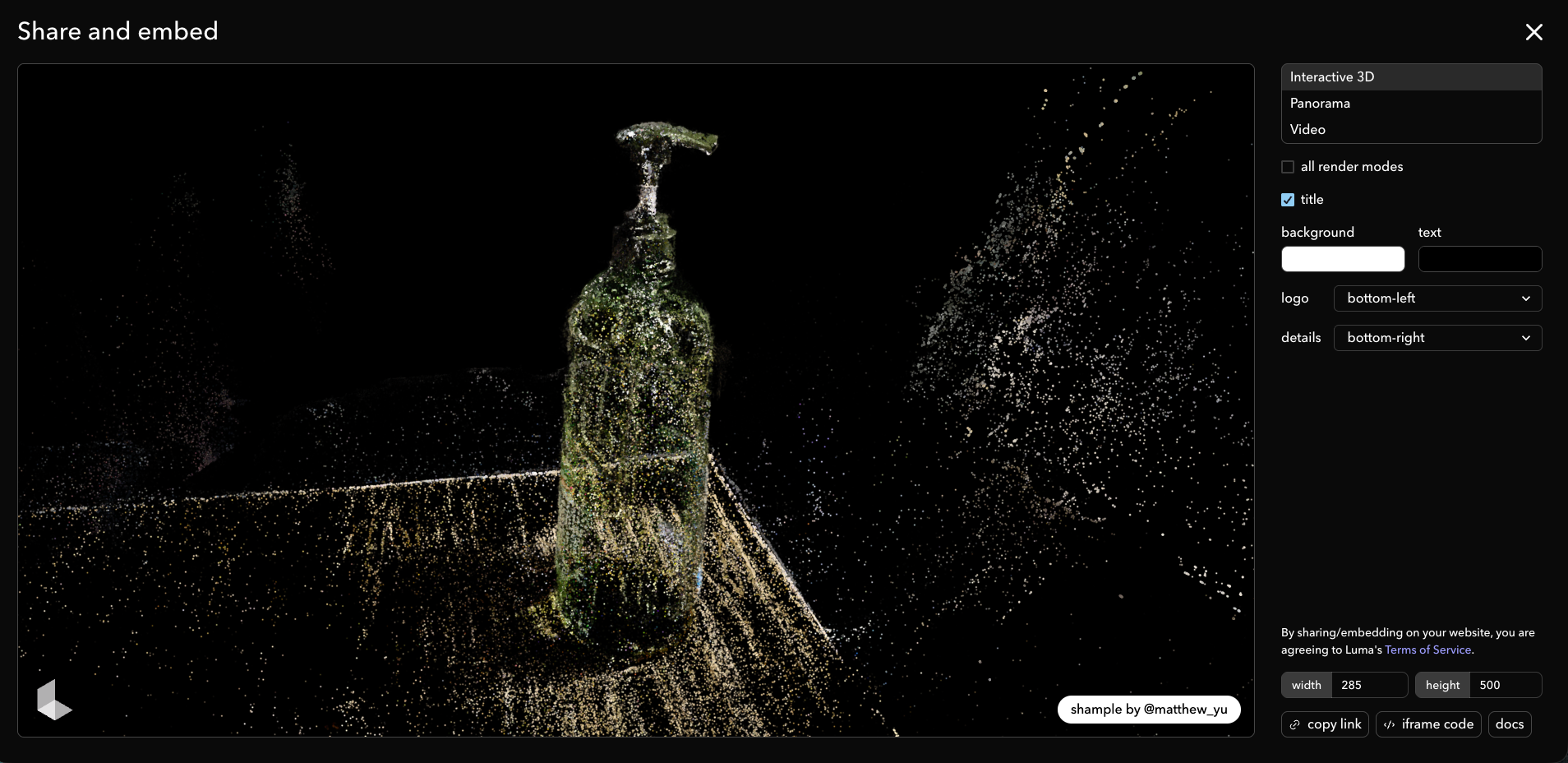
3.5 Luma AI Reconstruction Results
After Luma AI processing is completed, an interactive 3D model that can be rotated and viewed in a web page is generated. The main shapes of the bottle body and pump head can be seen in the model, and the desktop and surrounding environment are also partially reconstructed into a point cloud. Since Luma's display mode can show effects similar to point clouds or sparkles, a large number of colored dots can be seen in the image, which represent the spatial information reconstructed by the software from the images.
The scan result link is as follows: https://lumalabs.ai/capture/1af09b59-65b4-45ea-9b52-227513f7aca1
The embedded code is as follows:
The screenshot of the web page preview is as follows:
3.6 Model Export File
In addition to web page previews, Luma AI can also export model files. The Compressed Packet of the files I exported mainly contains:
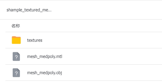
mesh_medpoly.obj: Scanned mesh model with medium polygon count;mesh_medpoly.mtl: Material file;textures/Folder: Texture images for the model surface.
This indicates that this scan not only generated a web display but also exported a textured mesh model that can be opened in Blender, MeshLab, or other 3D software. The OBJ file stores the geometric shape, and the texture file stores the color information. When combined, they can restore an appearance that is relatively close to the real object.
3.7 Post-processing and Model Quality Analysis
Original scanned models generally cannot be directly used for 3D printing. The reason is that models generated by photogrammetry are more focused on visual restoration rather than mechanical modeling. They retain desktops, background point clouds, and irregular surfaces, and may also have holes, noise, and non-closed meshes.
If this scan result is to be used for subsequent modeling or printing, the following post-processing steps need to be carried out:
- Remove redundant point clouds or meshes from the desktop and background;
- Cropping only retains the bottle-shaped object itself;
- Repair holes in the model to make the mesh as closed as possible;
- Simplify over-dense grids to reduce file size;
- Check the normal direction to avoid surface flipping;
- If you want to 3D print, you need to confirm that the model is a watertight mesh.
Based on the results of this experiment, Luma AI successfully reconstructed the general shape and texture of the object, with the bottle body, pump head, and the contact area with the desktop all recognizable. However, there are still some background points and scattered points in the results, indicating that the shooting environment and post-processing still affect the quality of the final model.
3.8 Summary
Through this scan, I understand that 3D scanning is not simply taking a photo, but a process of collecting spatial data from real objects. Luma AI has lowered the threshold of scanning, allowing me to complete 3D reconstruction by shooting with my phone, but the final result still depends on the object's material, lighting, shooting angle, and post-processing.
This scan completed the conversion from a real object to a digital model: first, a bottle-shaped object was photographed, then uploaded to the Luma AI cloud for reconstruction, and finally a web interactive model and a textured OBJ file were obtained. Although the scan results still need further cleaning before they can be used for 3D printing, they are already able to demonstrate the basic process and principles of 3D scanning.
Attachment
shample_textured_mesh_medpoly_obj.zip
Reference Link
Reference Software:https://lumalabs.ai/dashboard/captures
[!NOTE]
AI Assistance:
During the preparation of this documentation, ChatGPT (GPT-4) was used as a language assistance tool.
It helped with sentence polishing and translation from Chinese to English to improve readability and clarity.