Week 2: Computer Aided Design
During this week, we began to learn ** Computer Aided Design \(CAD\) **. In digital manufacturing projects, design is usually the first step in the entire production process.
Whether it is laser cutting, 3D printing, or CNC machining, it is necessary to first create a digital model through software. Therefore, mastering basic 2D and 3D modeling methods and learning to use appropriate CAD software tools are important foundations for subsequent production.
1.2D Design
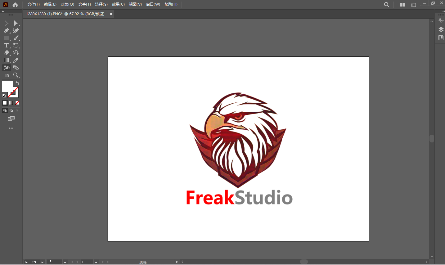
The object of this 2D design is the brand logo of my studio ** FreakStudio **.

The original logo is a grating image in PNG format, featuring an eagle\'s head and a shield base, with a color scheme dominated by dark red and white. Grating images suffer from pixelation issues when enlarged and are not suitable for scenarios requiring high-precision output, such as printing and engraving. Therefore, the goal of this exercise is to redraw it as a vector graphic, ensuring it remains clear at any size and serving as the design basis for subsequent processes like laser cutting or silk screening.
1.1 Grating Images and Vector Images
Before starting the design, it is necessary to understand two basic types of digital graphics:grating graphicsandvector graphics.
1.1.1 Grating Graphics \(Raster Graphics\)
Grating graphics are composed of pixels, which are tiny color blocks arranged in a grid. The clarity of an image depends on pixel density \(resolution\), so when magnified, the picture will become blurry or pixelated, and the quality will decline accordingly. Grating graphics excel at presenting content with delicate colors and rich layers, such as photos and paintings. Common formats: JPEG, PNG, GIF
1.1.2 Vector Graphics
Vector graphics, on the other hand, consist of paths and shapes defined by mathematical equations and are independent of pixels. This means that vector images can be scaled arbitrarily without distortion and always remain clear and sharp. Therefore, it is highly suitable for applications such as logos, icons, and product design drawings that need to be used in different sizes. Common formats: AI, SVG, EPS
| **Comparison Item ** | Grating Diagram \(Raster\) | Vector Graphics \(Vector\) |
|---|---|---|
| Composition Method | Composed of pixel lattices | Defined by mathematical paths and equations |
| Magnification effect | Blurry and pixelated after enlargement | Remains clear and sharp even when magnified |
| Applicable Scenarios | Photos, complex color images | Logo, icon, engineering drawing |
| Common Formats | JPEG、PNG、GIF | AI, SVG, EPS |
The original logo is in PNG format \(grating image\), featuring an eagle\'s head and a shield base, with color schemes mainly in dark red and white.
Grating images will exhibit pixelation issues when magnified and are not suitable for scenarios requiring high-precision output, such as printing and engraving.
Therefore, the goal of this exercise is to redraw it into AI format \(vector graphics\) so that it remains clear at any size, facilitating subsequent use in different sizes and processing scenarios.
1.2 Software Selection
For this 2D design, I chose Adobe Illustrator as the primary tool.
The reasons for selection are as follows:
-
Natively supports vector formats \(\.ai /\.svg /\.eps\), with no distortion when zooming
-
Built-in Image Trace function, which can automatically convert bitmaps into vector paths
-
Provides precise path editing tools to facilitate manual adjustment and optimization of tracing results
-
Supports exporting in multiple formats, adapting to the requirements of subsequent processes such as laser cutting and printing
1.3 Workflow
1.3.1 Import the original image
Open Adobe Illustrator, create a new artboard, and place the PNG file of the FreakStudio Logo onto the artboard.
1.3.2 Image Trace
Select the placed image, and in the top menu bar, choose Window → Image Trace to open the Image Trace panel.

Adjust the following parameters according to the color characteristics of the Logo:
-
Mode:Color
-
Number of colors: Adjust appropriately according to the effect
-
Path: Controls the fitting accuracy of the path
-
Noise: Filter out fine noise points
After adjustment is complete, click ** Expand ** to convert the tracing result into an editable vector path.
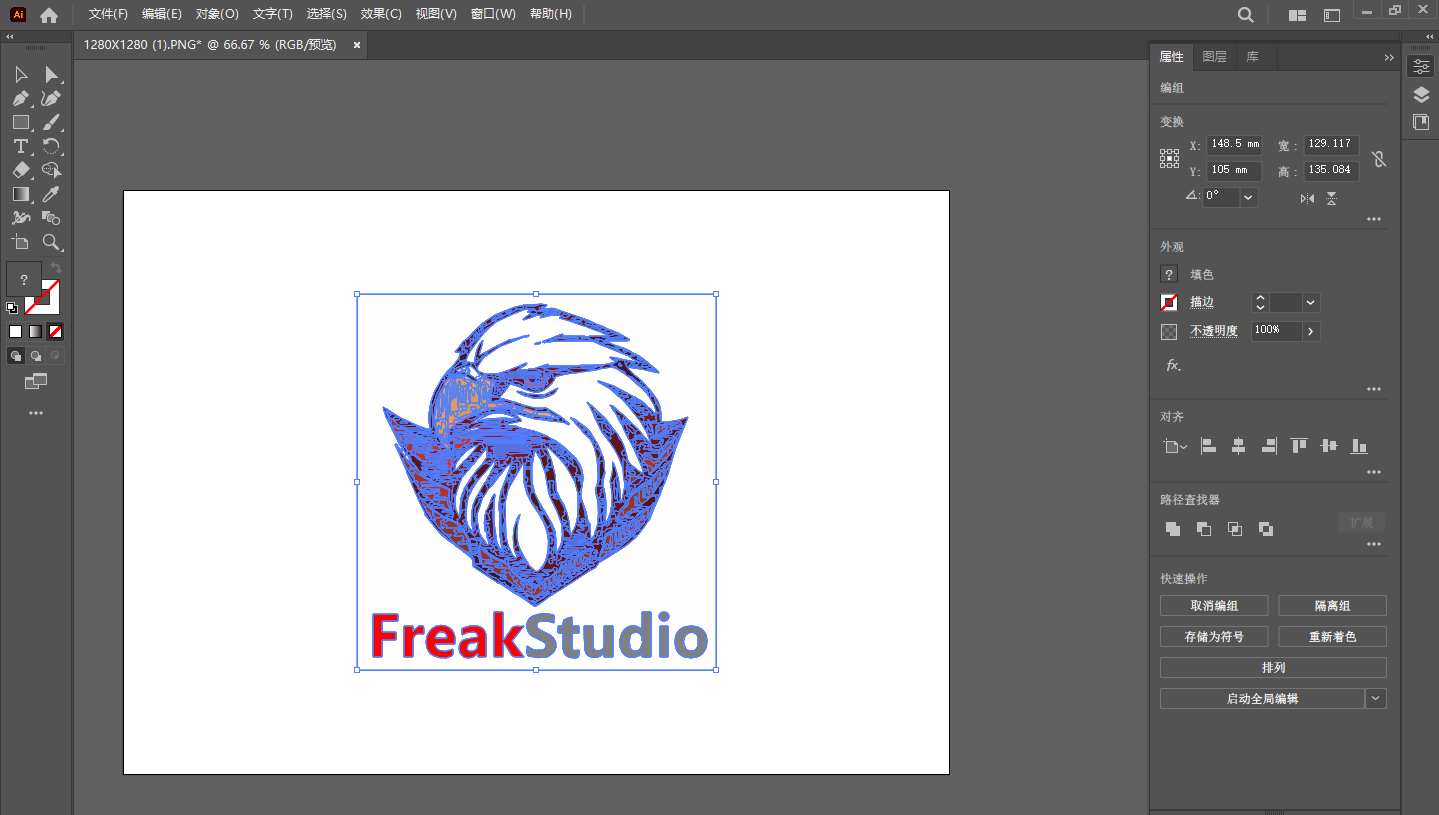
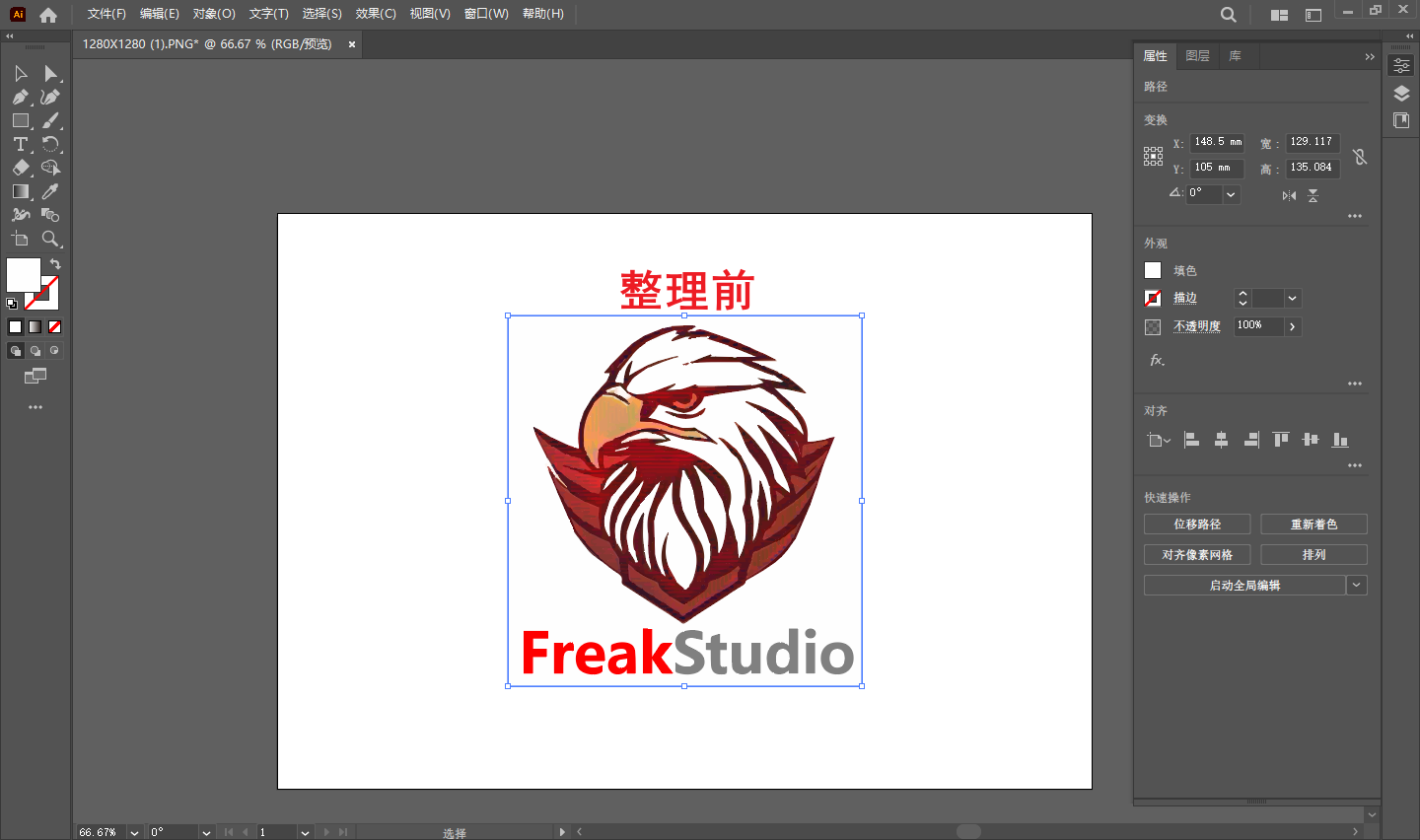
1.3.3 Path Arrangement and Optimization
Expanded vector graphics usually contain a large number of fragmented paths and need to be organized:
-
Ungroup and check the path structure layer by layer
-
Remove redundant background paths and noise points
-
Merge regions of the same color and simplify the layer structure
-
Check if the edges are smooth, and use theDirect Selection Tool \(A\)to manually adjust anchor points if necessary
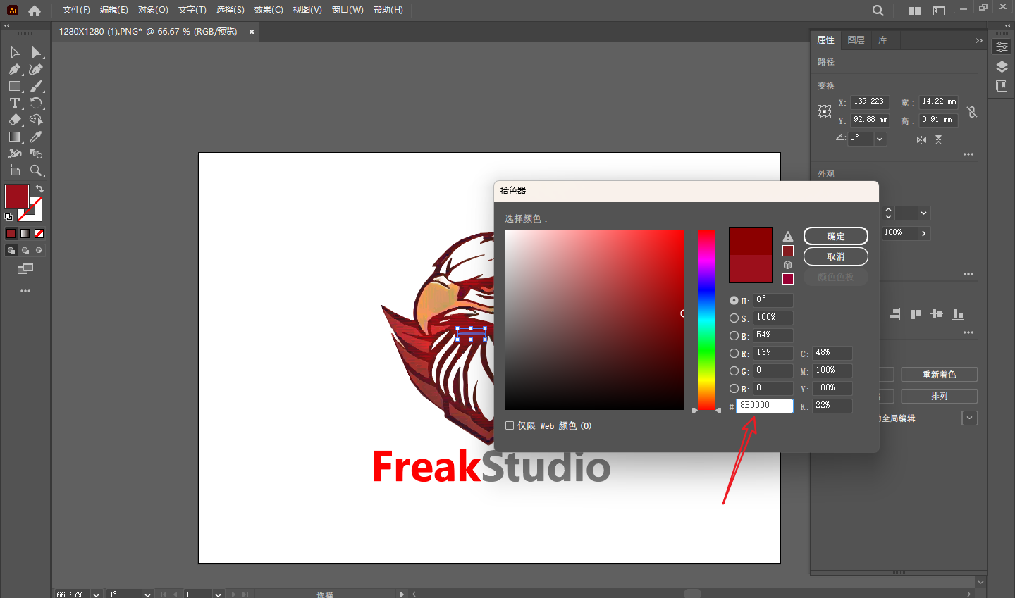
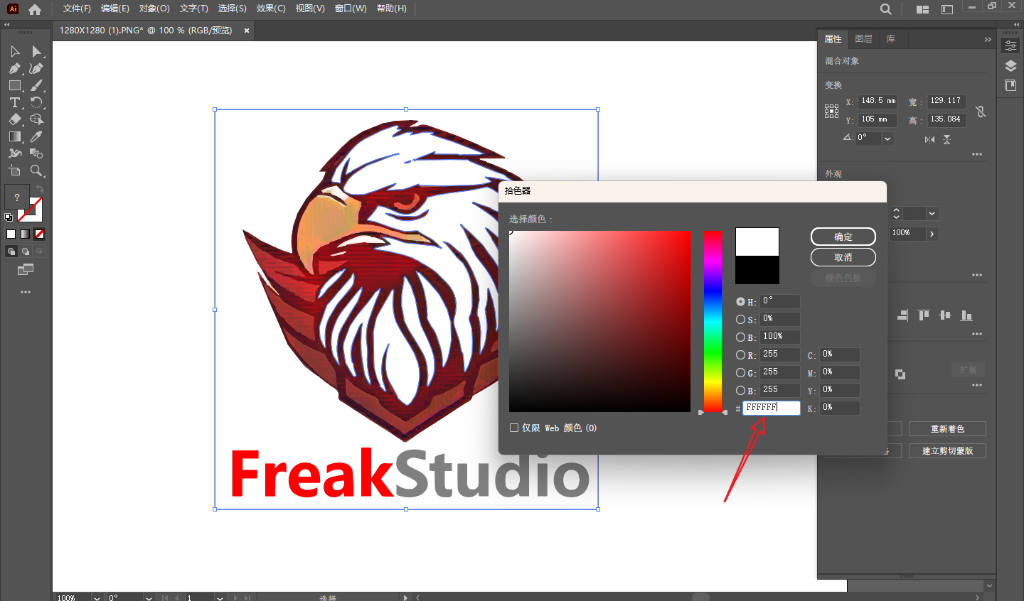
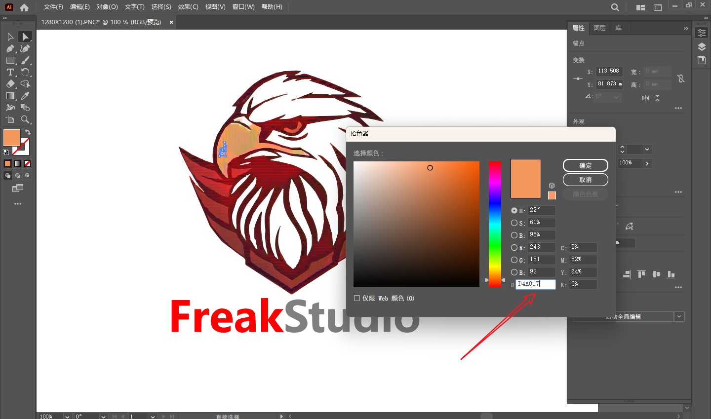
1.3.4 Color Verification and Adjustment
Compare with the original logo, check the color values of each part, and if there are any deviations, correct them one by one through thecolor filling panel.
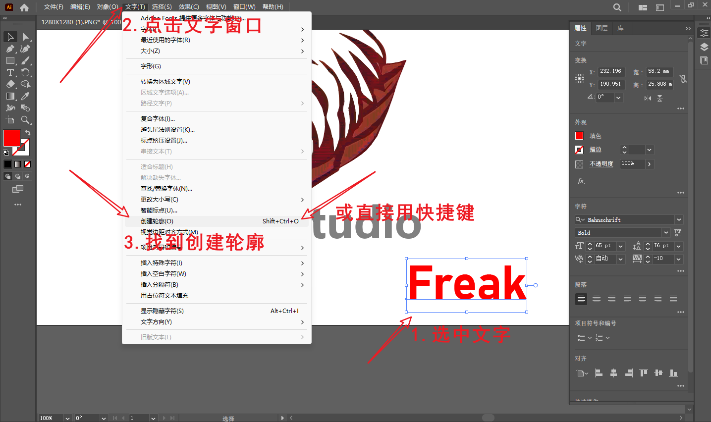
1.3.5 Text Part Processing
The text below the Logo ** FreakStudio ** also needs to be vectorized:
-
If the font is already installed, you can directly re-enter it in Illustrator to match the font and color
-
If the font is unknown, you can perform image tracing on the text area separately and then expand it into a path
-
After completion, perform ** Text → Create Outline ** on the text to ensure that the text is saved as a path and does not depend on font files
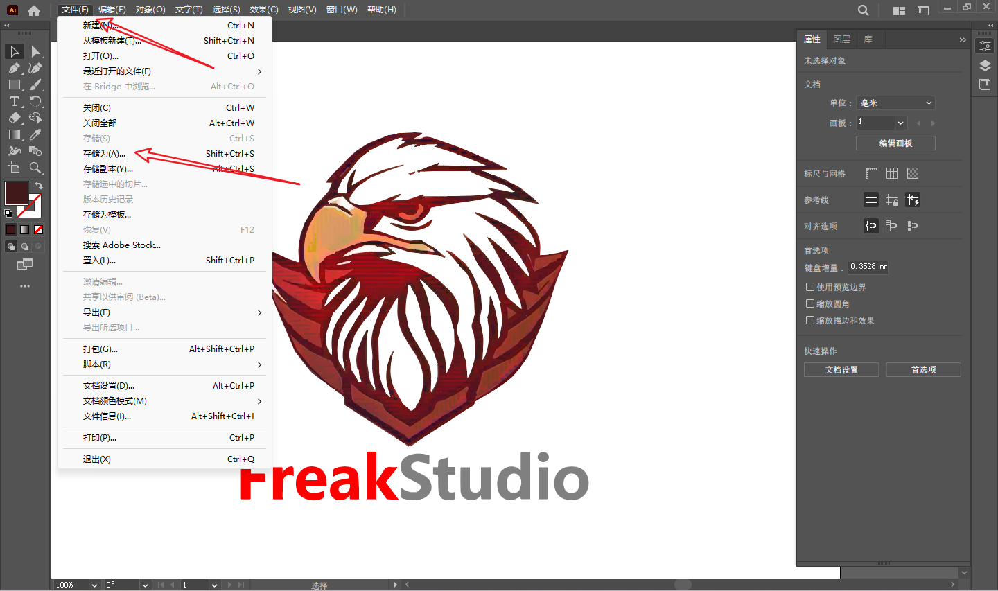
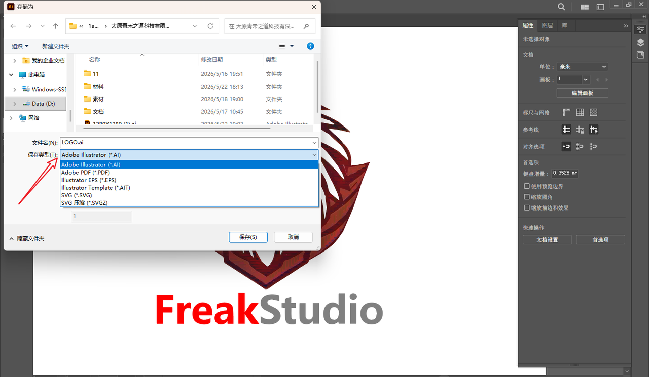
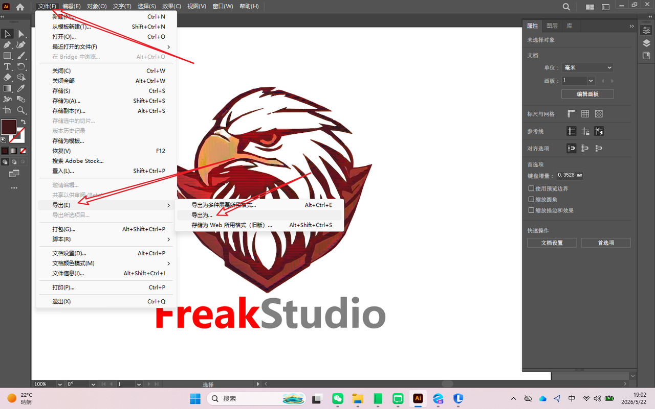
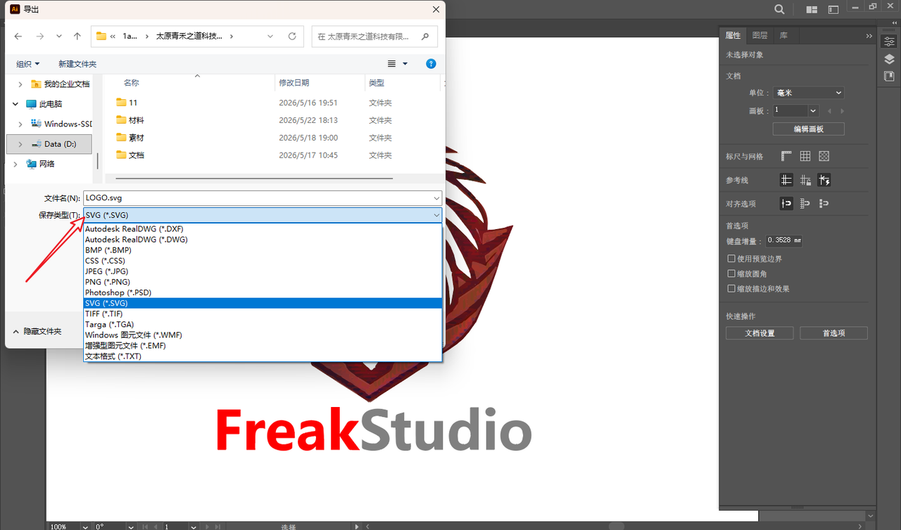
1.3.6 Export File
After completing all adjustments, export the vector logo in the following formats for future use:
-
\.ai: Illustrator source file, retaining editability -
\.svg: For web pages or subsequent digital manufacturing -
\.png\(High Resolution\): Used for document display
Menu Path:File → Export → Export As… / Save As…
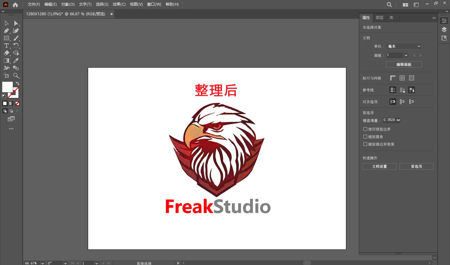
1.4 Final Effect
After vectorization, the FreakStudio Logo can maintain clarity at any size, with a complete path structure and accurate colors, and can be directly used for subsequent laser cutting, engraving, or printing output.


2.3D Design
2.1 Selection of Modeling Objects and Production Ideas
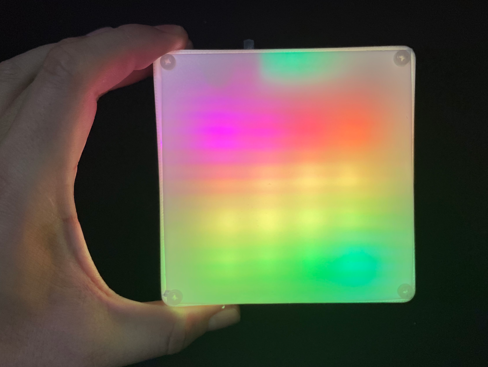
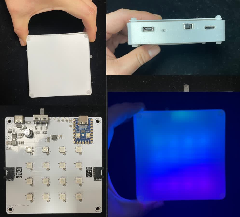
My goal this time is to design a housing for a previous electronic project, the NeoPixDot light chain pixel lamp. During this modeling process, I can simultaneously practice the design methods for 2D drawings and 3D solids.
My shell design is divided into two parts:
-
Top Cover: A square flat plate with screw holes pre-reserved at the four corners, used to close the housing and secure the overall structure, and used in combination with the housing body.
-
Shell body: Used to carry the PCB board, with reserved light-emitting holes for lamp beads and PCB mounting slots;
The top cover is designed in 2D, and after completion, it is exported as a \.DXF file for laser cutting acrylic and diffuser panels; the main body of the housing is modeled in 3D, with the bottom extruded to form a solid, and the \"Shell\" function is used to create an internal cavity to ensure space for PCB installation. Finally, 3D printing is used to verify dimensions and assembly effects.
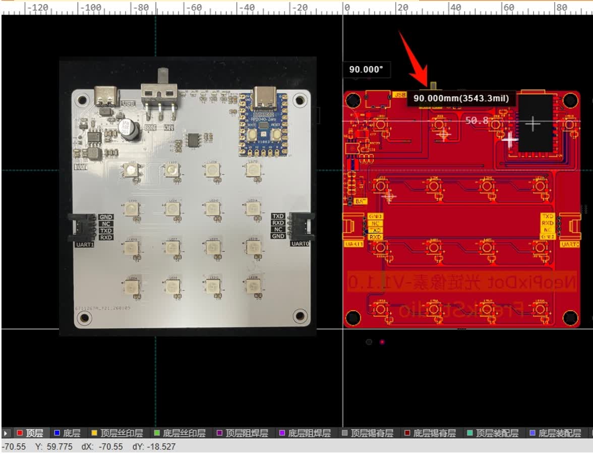
The core reference object for this modeling is the NeoPixDot light chain pixel lamp PCB, which has a square shape with a side length of 90mm. The main body of the enclosure I am about to design will be structured around the dimensions of this PCB to ensure that the PCB can be securely installed and meet the requirements of subsequent assembly.
2.2 Select a suitable CAD software
In this assignment, I need to select appropriate CAD software for 2D and 3D design. I mainly considered the following commonly used CAD software:
| Software | Core Advantages | **has deficiencies ** | **Adaptability Analysis ** |
|---|---|---|---|
| Fusion 360 | Integrated Function: Capable of completing 2D sketching and 3D solid modeling; Supports STL / DXF file export for convenient 3D printing and laser processing; Strong parametric modeling capabilities and user-friendly interface | Account registration is required, some features require an internet connection; new users may face a certain learning curve | Optimal choice, fully compatible with the requirements of this assignment and the final project |
| KiCad | Free and open source, suitable for PCB and electronic schematic design; can generate Gerber files for PCB fabrication | Primarily focused on PCBs, not suitable for housing mechanical structure modeling; 2D drawing capabilities are limited | Not suitable for this assignment |
| SolidWorks | Professional 3D mechanical modeling software, supporting complex parts and assemblies; comprehensive functionality and high precision | The software is expensive, has a high learning curve, and is slightly complex for simple shell design | Optional, suitable for complex mechanical parts, but slightly overkill for enclosure projects |
| FreeCAD | Free and open source, supports 2D/3D modeling, and can export STL/DXF files | The interface is complex, the modeling efficiency is low, and it is difficult for beginners to get started | is an alternative, but not a priority |
After comparison, I chose to use Fusion 360 because it can perform both 2D sketching and 3D modeling, and supports exporting STL or DXF files, which is convenient for 3D printing or laser processing. Meanwhile, its user-friendly interface and comprehensive functions make it very suitable for completing this week\'s modeling exercises.
Content above come from GPT4
2.3 Top Cover Design
The top cover is mainly used for light homogenization and closing the housing structure, and is fixed to the housing body by screws. Therefore, during the design process, it is necessary to reserve screw installation positions while ensuring that the dimensions can match the main structure, and it will be used in combination with the housing body we design later.
We plan to design the side length of the shell body to be 95.50mm and the side length of the top cover to be 90.10mm.
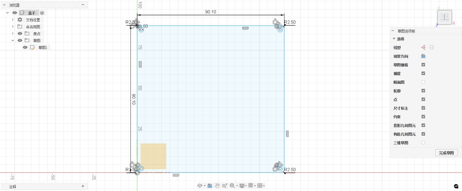
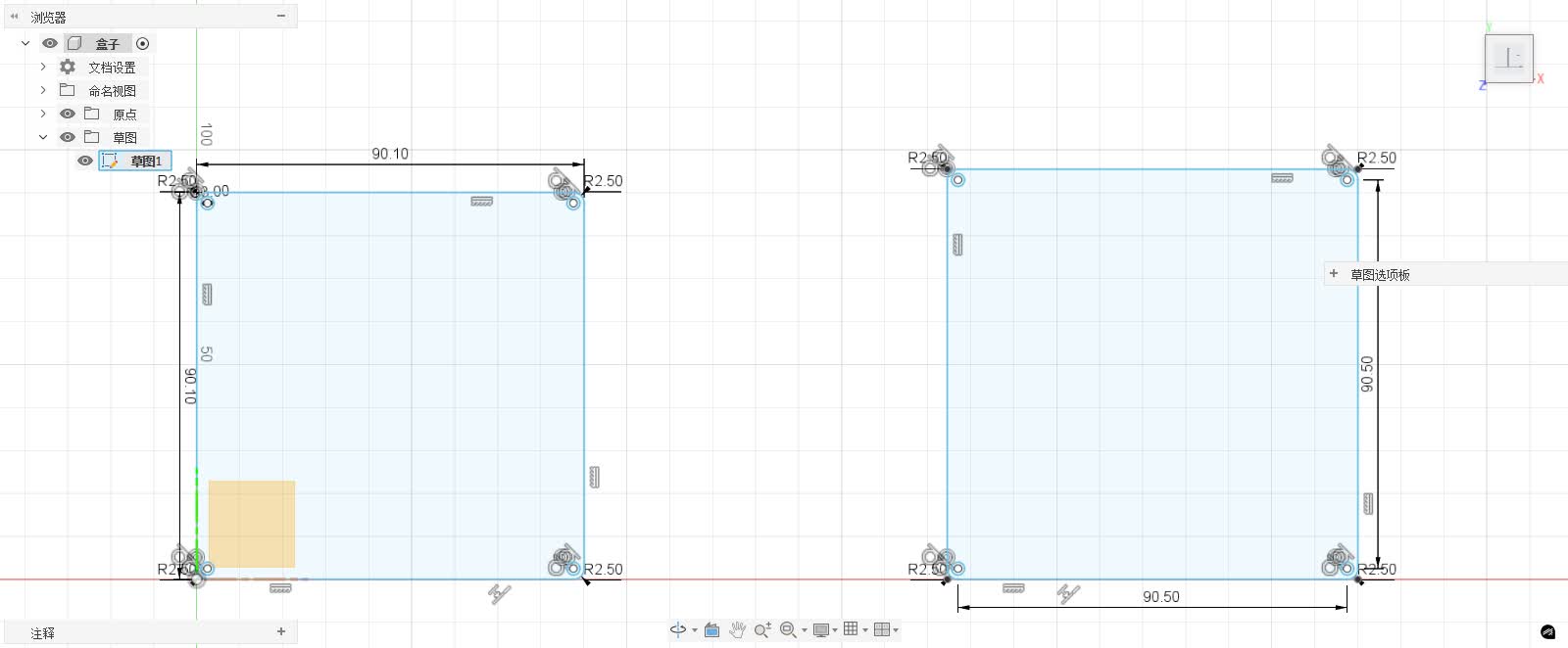
During the 2D design phase, I first drew a 90.10 mm × 90.10 mm square as the base outline of the top cover. Subsequently, 3 mm screw holes were reserved at the four corners for later securing the top cover to the main body of the housing with screws. The positions of the screw holes need to be symmetrical and correspond to the mounting posts in the main structure to ensure accurate alignment during assembly.
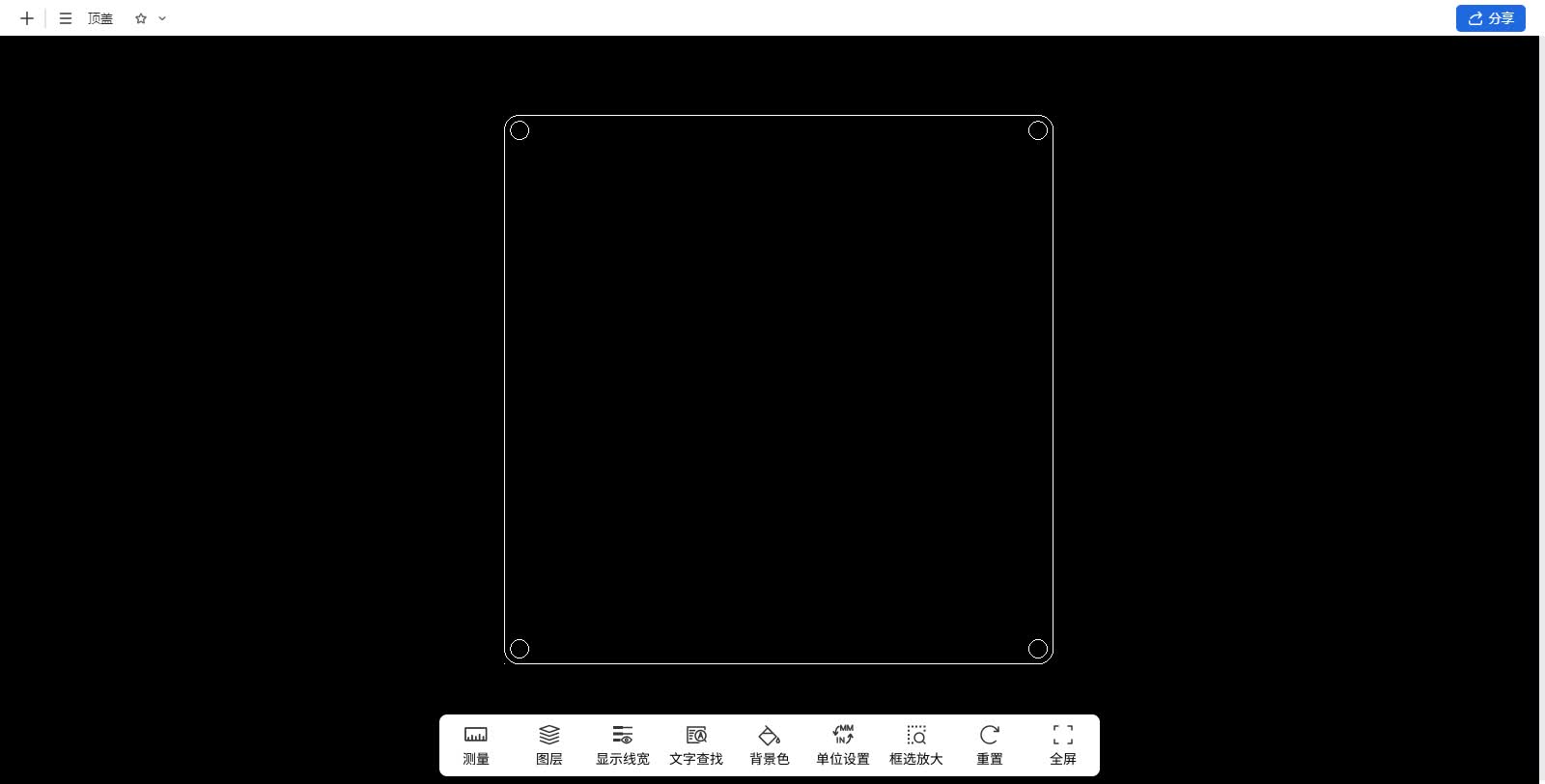
After completing the sketch, a simple check was conducted on the overall dimensions to confirm that there were no issues with the side lengths and hole positions. Subsequently, the 2D drawing was exported as a DXF file for subsequent use in laser cutting acrylic sheets and diffuser plates. In this way, the top cover structure can be quickly fabricated and combined with the 3D printed main body of the enclosure for testing.
2.4 Bottom Shell Modeling
2.4.1 Initial 2D Sketch
First, I create a Sketch in Fusion 360 and select the bottom plane as the drawing plane. According to the dimensions of the PCB, sufficient redundancy is reserved during design, with the side length of the enclosure body set to 95.50mm and the side length of the top cover set to 90.10mm. Four corner screw holes are also drawn at the four corners.
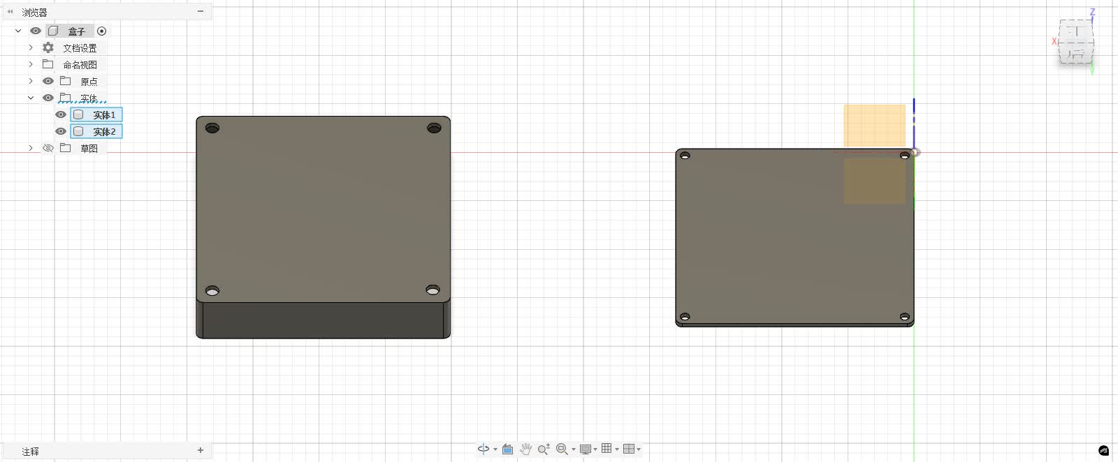
2.4.2 Preliminary 3D Modeling
After completing the 2D sketch, first extrude the shell body by a thickness of 2 cm to form a solid, then perform shelling and set the shell thickness to 2 mm, while the top cover is extruded by a thickness of 2 mm to form a preliminary flat plate.
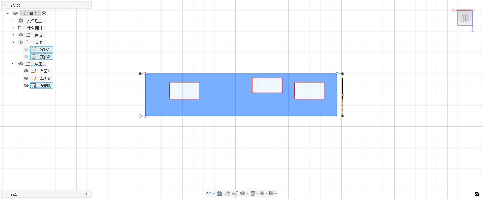
2.4.3 Secondary Sketch and Additional Modeling
Perform secondary operations on the stretched solid, create a new sketch on the side of the housing body, draw the contour of the hole position to be cut out, and expose the switches and interfaces of the light chain pixels.
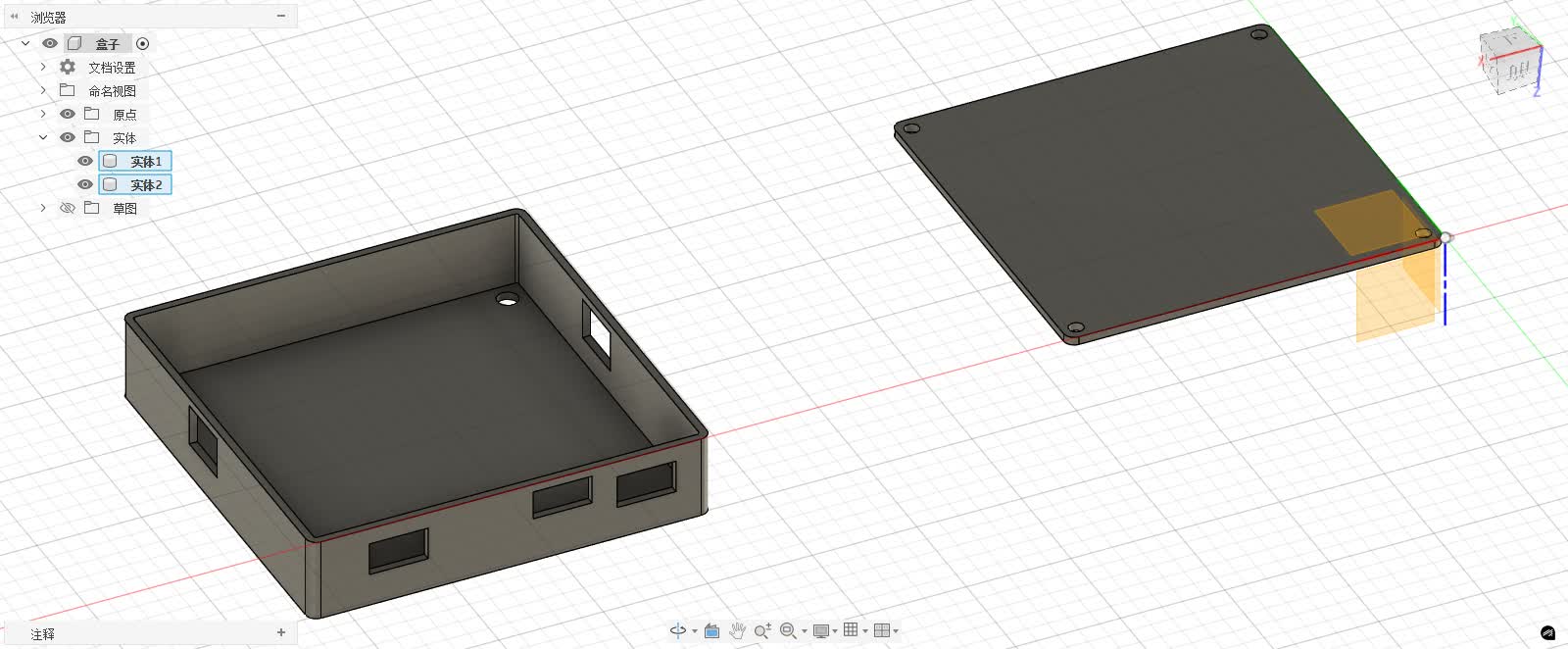
Through the above process, I completed the full modeling from 2D sketches to 3D solids and then to functional holes.
2.4.4 Physical Manufacturing and Testing
After completing the 3D modeling, I exported the main body of the housing as an STL file and printed it using a 3D printer, while exporting the top cover as a DXF file in the 2D sketch section and processing it with a laser engraver.
The final display effect is shown in the figure below:
3. Compression of Images and Videos
3.1 Image Compression:Squoosh
While organizing the assignment, I found that the original screenshot and photo files were relatively large, and if not compressed, the entire assignment package might exceed 200MB. To control the size, I used Squoosh to compress the images.
Squoosh is an online tool developed by Google, with simple operation and excellent compression results. The specific operation steps are as follows:
**Step 1: ** Open the Squoosh online tool: https://squoosh.app/ \(English version\) or https://www.starfavor.cn/compress/ \(Chinese version\);
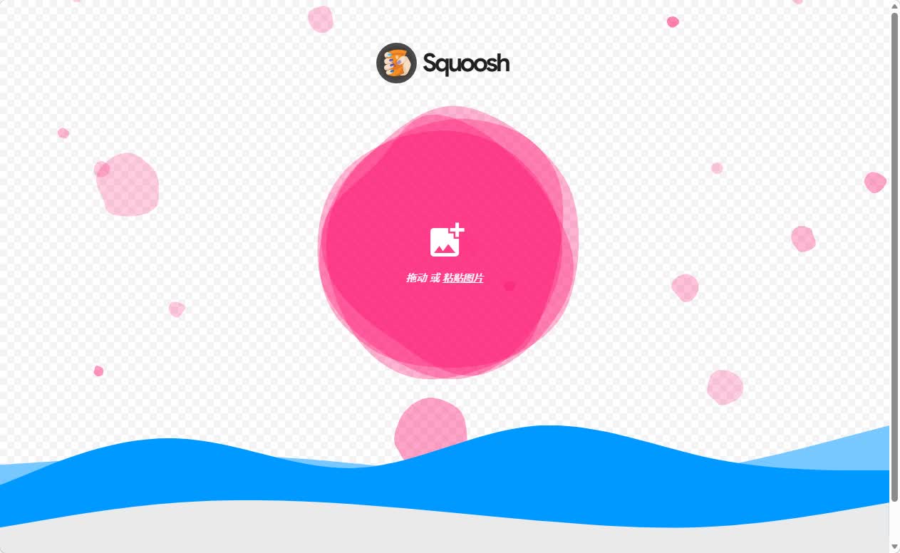
**Step 2: ** After dragging the images to be compressed onto the Squoosh interface, you can set the image format, post-compression quality, and image size. Moreover, the web interface will display the compressed effect in real time, allowing us to confirm that there is no significant loss of image quality before downloading.
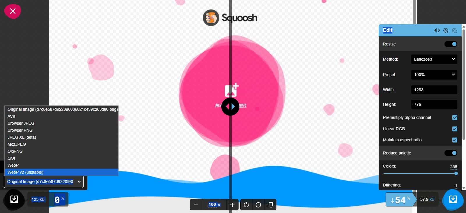
Step 3: After confirming the parameters, click Export and save the compressed image.
3.2 Video Compression: FFmpeg
FFmpeg is a very powerful command-line tool that is highly professional for video compression. Although it requires entering a few commands, the results are highly controllable and the steps are not complicated. The specific operation steps are as follows:
3.2.1 Install FFmpeg
Open the Dpwnload FFmpeg official website: https://ffmpeg.org/download.html , select the installation packagewindows builds from gyan\.dev.
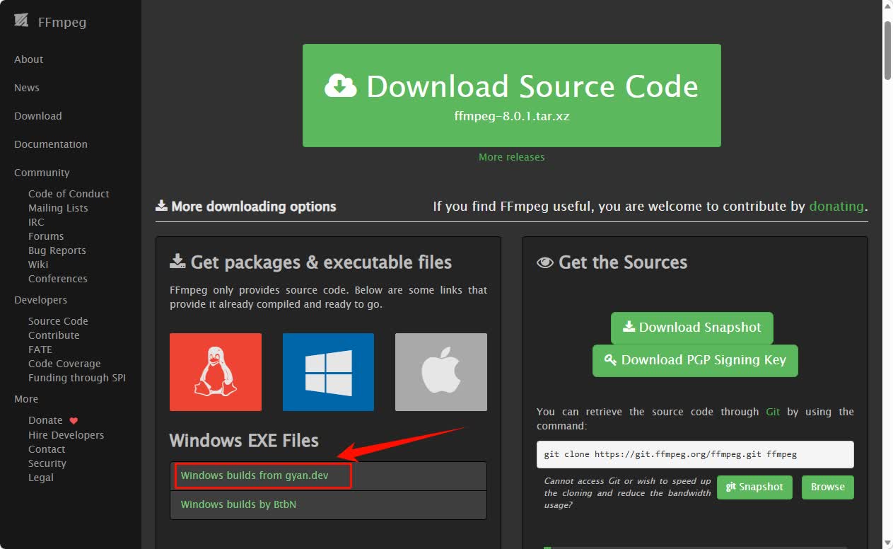
Scroll down to find therelease buildssection, selectffmpeg\-7\.1\.1\-essentials\_build\.7zto download. This version is a streamlined core version, containing all the functions required for compression, with a small size and strong adaptability, suitable for homework use.
After the download is complete, unzip the file to obtain the FFmpeg folder, check the folder structure, which mainly contains three directories:
-
bin: The folder where the FFmpeg executable file is located. All commands to run FFmpeg must be executed through the files in this directory. -
doc: Document materials. -
presets: Preset format and encoding scheme.
Enter bin directory, you can see the three core executable files of FFmpeg:
-
ffmpeg\.exe: Mainly used for video processing -
ffplay\.exe: Used for playing videos -
ffprobe\.exe: Used for analyzing video information
To ensure that the system can recognize the FFmpeg command in any folder location, we need to add its bin directory path to the system\'s \"environment variables\".
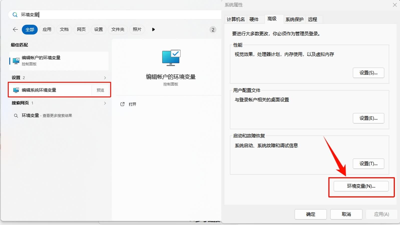
Enter \" environment variables *\" in the Windows search bar, then select \" *Edit system environment variables \". In the pop-up \"System Properties\" window, click the \" *environment variables \(N\)... *\" button at the bottom.
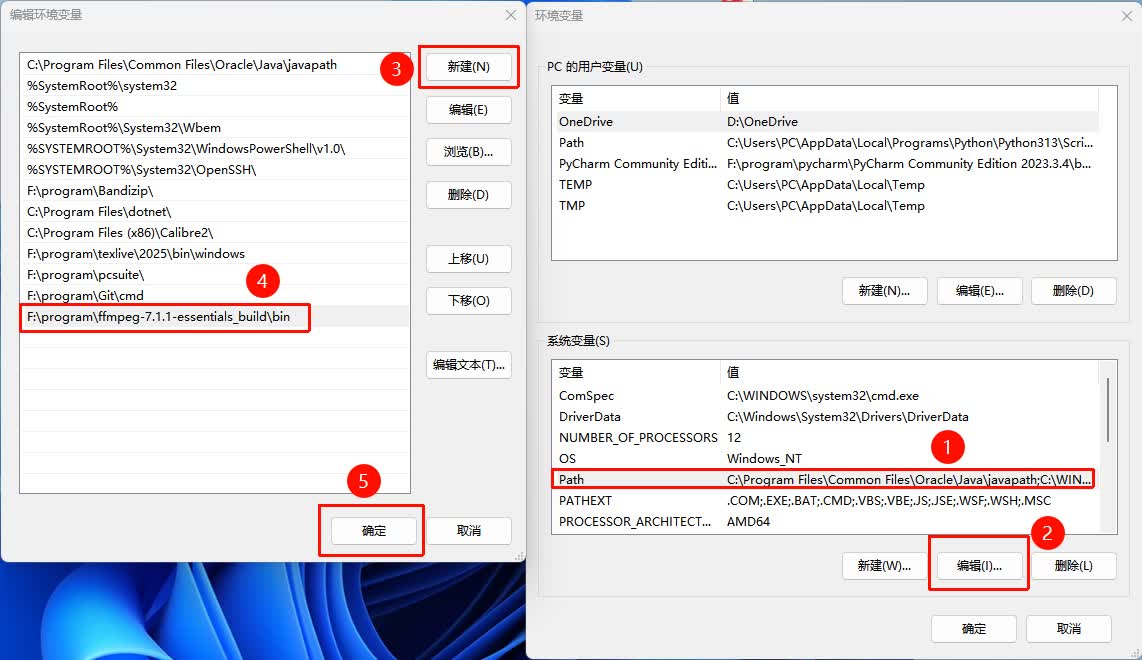
In the open environment variables window, in the of the \" System Variables *\" area, find and select the variable named Path, click the \" *Edit... **\" button below, and a blank input line will be added. The full path of the binfolder you just copied, for example: F:\\ program\\ ffmpeg \- 7\.1\.1 \- essentials\_build\\ binPaste it in, and finally click \"OK\" all the way to save and close all open property windows.
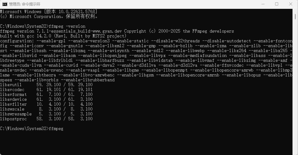
In the new command line window, enter the following command and press Enter:
The command line displays a long string of text including detailed version information, compilation configuration, etc. of FFmpeg, rather than prompting "'ffmpeg' is not an internal or external command...". This proves that FFmpeg has been successfully installed and configured and can be invoked from any location in the system.
At this point, the installation and configuration of FFmpeg are all completed. Next, I can directly call the ffmpeg command using the command line in any folder to compress videos. The next step will introduce the specific usage of the compression command.
3.2.2 Compressed Video
After installation and configuration are complete, you can now open the Command Line Tool \(CMD\) in any folder to use FFmpeg to compress videos. The basic idea is to specify the input file, output file, and key compression parameters through a simple command.
Below is my operation record:
**Step 1: Open the command line **
You can use CMD to navigate to any directory without having to enter the directory where the video file is located, or you can directly write the full path.
**Step 2: Enter the compression command **
The basic command format is as follows:
Parameter Description:
-
\-i Input video path: Specify the path of the original video file -
\-vcodec libx264: Use H.264 video encoding -
\-crf 23: Controls video quality, where a smaller value indicates higher quality, and a value around 23 results in a video quality that is not significantly different from the original video -
\-preset medium: Balances compression speed and effect, with options slow, medium, fast -
\-acodec aac: Compresses audio while ensuring sound quality -
Output Video Path: Save path for the compressed video file
Step 3: Wait for compression to complete
After executing the command, the command line will display compression progress and frame rate information, and a compressed video file will be generated upon completion.
Step 4: Check video quality
Play the output video to confirm that there is no obvious blurring, lagging, or audio-video desynchronization in the picture quality. Once satisfied, you can use the compressed video for assignment submission or sharing.
4. Design and Processing Documents
5. Related Links
Fusion 360 Learning Link: https://docs.geeksman.com/print3D/
FFmpeg Installation Tutorial: https://blog.csdn.net/Natsuago/article/details/143231558
Adobe Illustrator Full Version Installation Link: https://www.yuque.com/qianxun-nzpyh/ttnizd/wgg6ax#%20
[!NOTE]
AI Assistance:
During the preparation of this documentation, ChatGPT \(GPT\-4\) was used as a language assistance tool.
It helped with sentence polishing and translation from Chinese to English to improve readability and clarity.