Week 10 - Output Devices
This week we start learning about output devices (Output Devices) . If input devices are responsible for enabling the microcontroller to sense the external environment, then output devices are what allow the system to feed back the processing results to the user or the external world. Common output devices include LEDs, OLED/LCD displays, buzzers, vibration motors, servos, and motors, among others.
Output devices are very important in embedded projects because they directly determine how the system "expresses its state". For example, a display screen can show sensor data, an LED can indicate the working status, and a vibration motor can provide tactile feedback. Meanwhile, output devices are usually the more power-consuming parts of a circuit, so when designing, one must consider not only the control method but also power consumption.
Group assignment:
The group assignment mainly involves using test equipment such as digital multimeters, DC power supplies, and oscilloscopes to measure the power consumption of output devices and record the test process and results. This group chose to test the 0.96-inch SSD1306 OLED display module , observing its voltage, current, and power consumption under operating conditions through a DC power supply.
Individual assignment:
Individual assignments require integrating at least one output device on a self-designed microcontroller development board and implementing control through a program. This time, I choose to use a 0.96-inch SSD1306 OLED display as the output device, while combining it with the DHT22 temperature and humidity sensor used last week to achieve temperature and humidity data acquisition and real-time OLED display, completing a complete closed loop from input to output.
Overall, the focus of this week has been on understanding the control methods and power consumption characteristics of output devices. Through the OLED display, I have learned about the connection method of I2C output devices, driver programming, data display refresh, and how to use the power supply device to estimate module power consumption.
Group Assignment
Group Assignment Page: https://fabacademy.org/2026/labs/chaihuo/docs/week10/chaihuo/week10_group_assignment
1. Test Approach for Output Device Power Consumption
The core of this week's group assignment is to measure the power consumption of output devices . Output devices differ from input devices in that they typically require more electrical energy to produce visible, audible, or motion feedback, such as screen illumination, motor rotation, speaker sound, etc. Therefore, when designing embedded systems, we cannot only consider whether the device can operate, but also need to consider how much current it will consume under different operating conditions.
We compared several common types of output devices by referring to the test content on the group page:
| Output Device | Output Format | Power Consumption Characteristics | Typical Applications |
|---|---|---|---|
| OLED Display | Visual Display | Low power consumption, varying with the number of lit pixels | Data Display, Status Indication |
| Speaker | Sound Output | Varying with frequency, volume, and driving mode | Prompt tone, Alarm |
| Mini Fan | Continuous rotation | Power consumption is significantly higher than that of display devices | Heat Dissipation, Airflow Feedback |
| BLDC Brushless Motor | High-speed rotation | High current requires ESC drive | Fan, Drone, Continuous Motion Mechanism |
By comparison, it can be found that the power consumption of different output devices varies greatly. Display devices such as OLEDs are usually suitable for being directly powered by the development board, while output devices such as motors often require a separate power supply and driver module and cannot be directly connected to the GPIO of the microcontroller.
2. Test Equipment and Safety Precautions
The following devices were mainly used in this power consumption test:
- Adjustable DC Power Supply: Used to provide a stable voltage and read the output current.
- Digital Multimeter: Used to assist in measuring voltage, current, and circuit continuity.
- Oscilloscope: Can be used to observe control signals such as PWM.
- Output device module: OLED, speaker, small fan, motor, etc.
When measuring power consumption, special attention must be paid to the current and voltage ranges. Low-power modules typically only require a few tens of milliamps, but motor-type output devices may instantaneously draw high current during startup or stall. If the power supply or driver is not selected correctly, it may trigger overcurrent protection and even damage the device.
Especially BLDC brushless motors, which usually cannot be directly driven by a development board but require an ESC (Electronic Speed Controller) for control. The ESC adjusts the motor speed according to the PWM control signal and also undertakes the task of high-current driving. When testing such devices, it is necessary to first confirm whether the motor, ESC, and power supply voltage are matched.
3.0.96-inch SSD1306 OLED Module Power Consumption Test
In the part I am personally responsible for, the test object is a 0.96-inch SSD1306 OLED display module . OLED is an organic light-emitting diode display, where each pixel can emit light actively, so it does not require a backlight. Compared to ordinary LCDs, OLED has higher contrast, displays text and simple graphics very clearly, and is suitable for status display on small embedded devices.
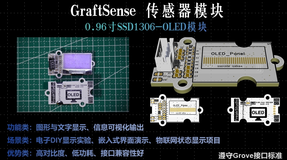
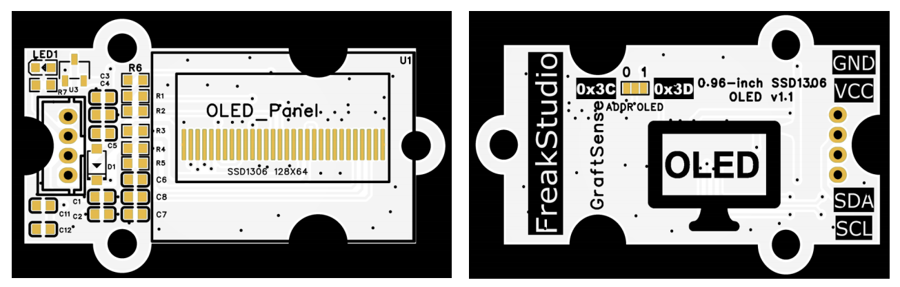
SSD1306 OLED modules typically use the I2C communication interface, requiring only SDA and SCL two signal lines to communicate with the microcontroller, plus VCC and GND for power supply, making the wiring relatively simple.
3.1 Test Method
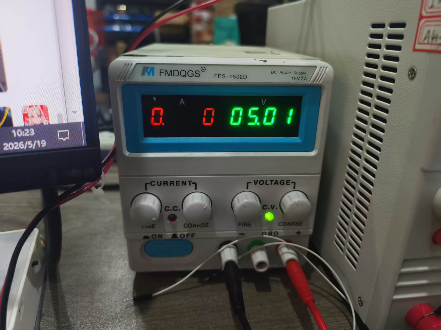
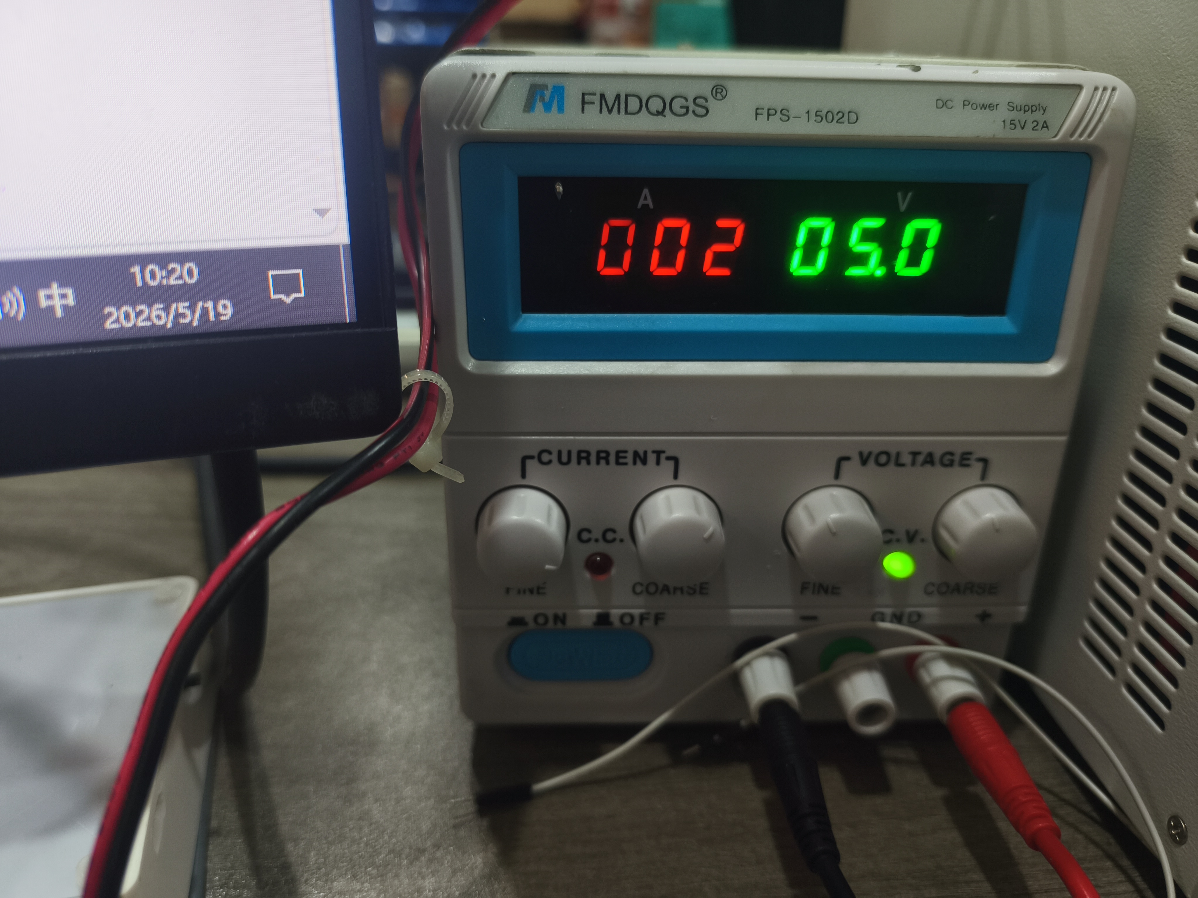
To measure the power consumption of the OLED module under operating conditions, we use an adjustable DC power supply to power the OLED module and read the voltage and current displayed on the power supply.
The test connection method is as follows:
- The positive pole of the power supply is connected to the
VCC / 5Vpin of the OLED module. - The negative electrode of the power supply is connected to the
GNDpin of the OLED module. - Set the DC power supply voltage to 5.00 V.
- Run the program to make the OLED enter the normal display state.
- Observe the current value displayed on the DC power supply.
I connected the black wire to GND, and the red wire to 5V pin.
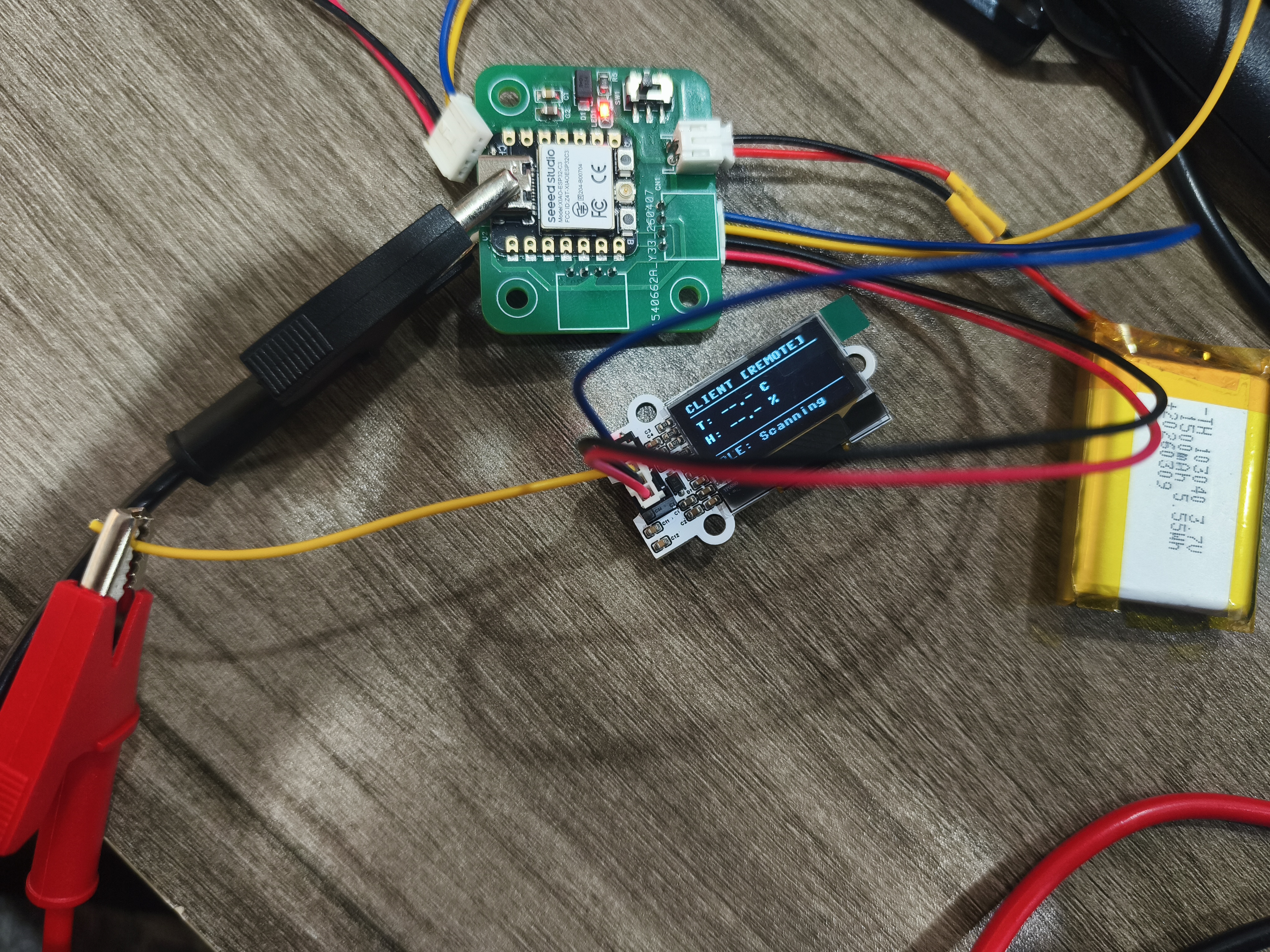
Next, set the voltage of the DC power supply to 5.00 V.
After turning on the power, run the OLED display program to bring the screen into normal operating state.

Observe the voltage and current displayed on the adjustable power supply at this time.
3.2 Power Consumption Calculation
The power consumption of the output device can be calculated by voltage and current:
P = U × I
Where:
Pis power consumption, with the unit of W;Uis the supply voltage, with the unit V;Iis the operating current, with the unit of A.
During this test, the supply voltage was set to 5.00 V. The current reading needs to be recorded according to the DC power supply display. If the current is I when the OLED is displaying normally, then the power consumption is:
P = 5.00 V × I
For example, if the current is approximately 0.02 A, then the power consumption is approximately:
P = 5.00 V × 0.02 A = 0.10 W
The power consumption of OLED is related to the display content. If more pixels on the screen are lit, the overall current will increase; if there is less content to display, the current will decrease. Therefore, in low-power projects, power consumption can be reduced by lowering the brightness, reducing the refresh rate, or turning off the display when idle.
4. Comparison of Power Consumption of Motor-Type Output Devices
Referring to the tests on the group page, the power consumption of motor-type output devices is much higher than that of display modules such as OLEDs. For example, when the Grove Mini Fan operates at 5V, the current can reach several hundred milliamperes, with power consumption approaching the watt level; if the fan rotation is manually blocked, the motor will enter a state close to locked rotor, and the current will further increase.
This indicates that the motor power consumption is not only related to the supply voltage but also to the load state:
- When idling, the current is relatively low;
- At the moment of startup, the current will increase;
- When the load increases, the current continues to rise;
- During locked-rotor conditions, the current may reach its maximum value, which can easily damage the motor or drive.
The group page also records the BLDC brushless motor test. The brushless motor needs to be controlled by an ESC, which drives the three-phase windings of the motor after receiving the PWM signal. It is suitable for scenarios requiring high-speed, smooth, and continuous rotation, but its power consumption and current are significantly higher than those of small display modules.
When testing a BLDC motor, the most important experience is: First, the rated voltage of the device and the specifications of the driver must be confirmed . If a voltage exceeding the allowable range of the ESC or motor is used, the power supply may enter constant current protection mode, or even damage the ESC. This case made me realize that testing output devices should not only focus on "whether it can move", but also on rated voltage, current, load, and protection mechanisms.
5. Summary of Group Assignment
Through this group test, I have learned the basic methods for measuring the power consumption of output devices. Compared to simply checking whether a module can display, power consumption testing can help us determine whether a device is suitable for battery-powered projects.
For OLED modules, their wiring is simple, display is clear, and they are suitable for small interactive devices. However, if a project requires long-term battery operation, attention needs to be paid to its operating current, and the display content and refresh rate should be reasonably controlled in software.
By comparing with motor-type output devices, I also found that the power consumption differences among output devices are very significant. OLED is suitable for low-power information display, while devices such as motors and fans require separate consideration of driving capability and power supply capacity. This conclusion also directly affects my personal project: my temperature and humidity display device uses an OLED as the output device, with relatively controllable power consumption, so it is more suitable for subsequent development into a small battery-powered environmental monitoring device.
Individual Assignment
1. Temperature and humidity display device
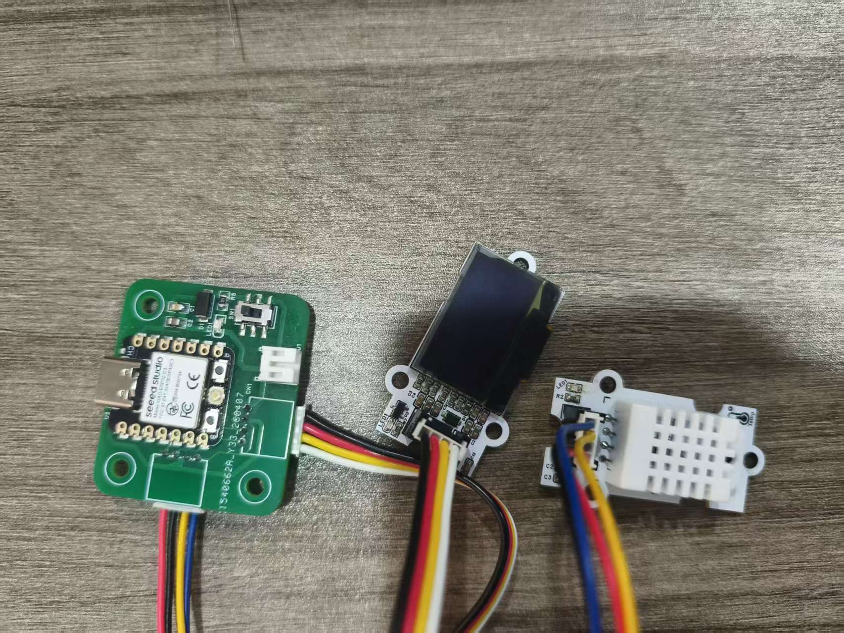
The goal of this individual assignment is to create a simple temperature and humidity display device . The system consists of three parts:
- Self-designed ESP32-C3/XIAO-C3 development board;
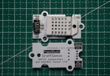
- DHT22 Temperature and Humidity Sensor Module;
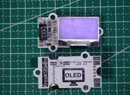
- 0.96-inch SSD1306 OLED display module.
The DHT22, as an input device, is responsible for collecting ambient temperature and humidity, while the OLED, as an output device, is responsible for displaying data. This can form a complete data flow: the sensor collects data, the main controller processes the data, and the display outputs the results.
2. Hardware Connection
The input device uses the GraftSense DHT22-based temperature and humidity sensor module , and the output device uses the GraftSense 0.96-inch SSD1306 OLED module , both of which are connected to the self-developed board.
The connection method is as follows:
| Module | Pin | Connect to the development board |
|---|---|---|
| OLED | SDA | GPIO6 |
| OLED | SCL | GPIO7 |
| OLED | VCC | 5V / 3V3 (according to module requirements) |
| OLED | GND | GND |
| DHT22 | DATA | GPIO20 |
| DHT22 | VCC | 5V / 3V3 (according to module requirements) |
| DHT22 | GND | GND |
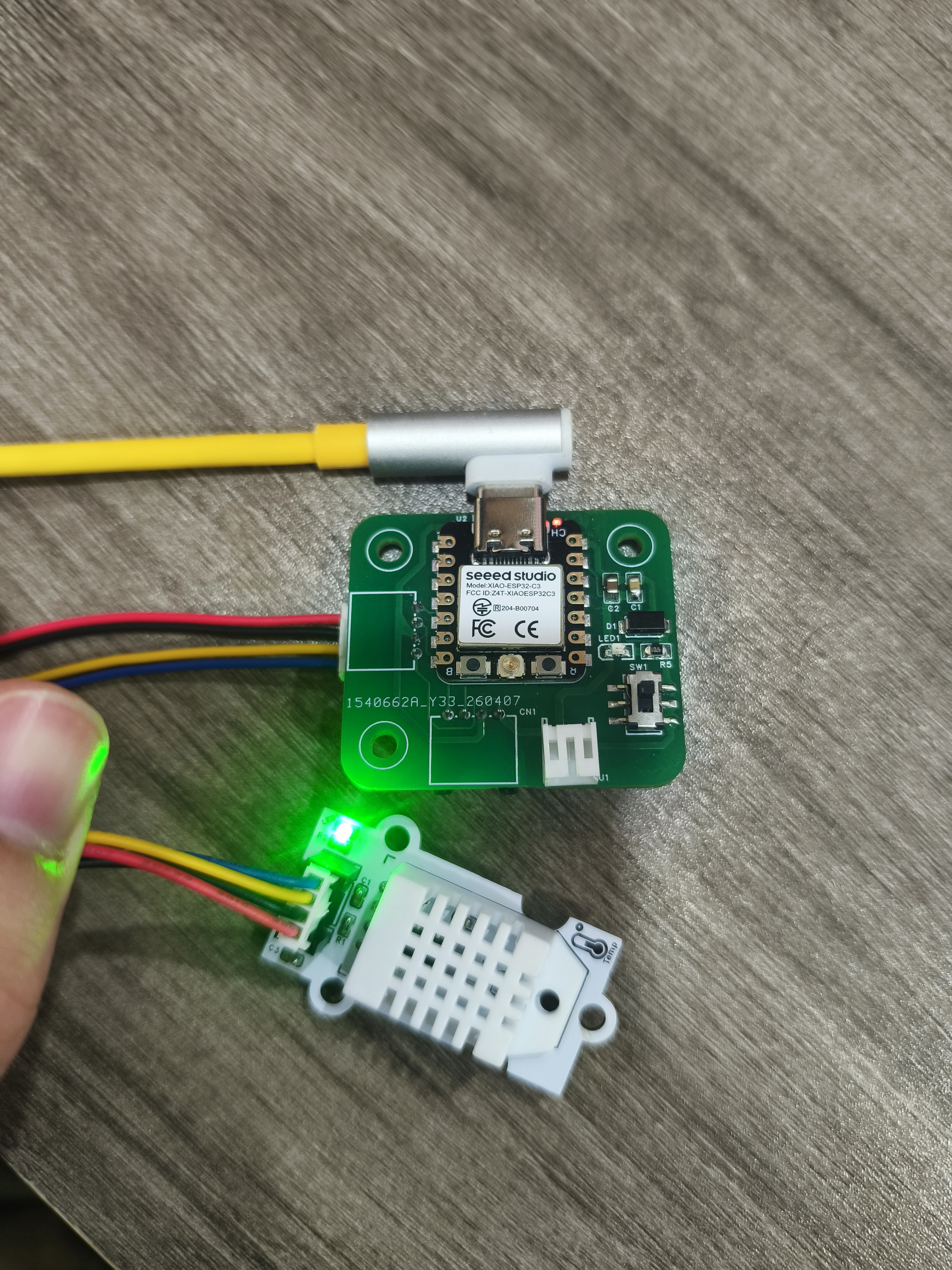
OLED uses I2C communication, so it only requires SDA and SCL two signal lines. DHT22 uses single data line communication, sending temperature and humidity data to the main controller through DATA pin.
3. Programming Design
The program mainly performs the following functions:
- Initialize the I2C bus and connect the OLED screen.
- Initialize the DHT22 temperature and humidity sensor.
- Read temperature and humidity every 2 seconds.
- Format the data to one decimal place.
- Simultaneously display data via serial port and OLED.
- If the reading fails, display an error message on the OLED.
The program logic is as follows:
- Hardware Initialization: Start the I2C bus, initialize the OLED and DHT22.
- Read data in a loop: Call
dht_sensor.measure()to trigger data collection. - Data Processing: Read temperature
tempand humidityhum, keeping 1 decimal place. - Output Display: Serial port prints debugging information while refreshing the OLED screen.
- Exception Handling: If sensor reading fails, the screen displays
Sensor Error!.
# Python env   : MicroPython v1.23.0
# -*- coding: utf-8 -*-
# @Time    : 2025/9/1
# @Author  : ben0i0d
# @File    : main.py
# @Description : DHT22 + SSD1306 Temperature and Humidity Display

# ======================================== Import Modules =========================================
from machine import Pin, I2C
import time
import dht
from ssd1306 import SSD1306_I2C

# ======================================== Hardware Initialization ======================================
time.sleep(2)
print("DHT22 + OLED Temperature Humidity Display Started...")

# I2C Initialization for OLED
i2c = I2C(0, sda=Pin(6), scl=Pin(7), freq=400000)

# OLED Initialization (128x64, I2C address 0x3C)
oled_width = 128
oled_height = 64
oled = SSD1306_I2C(i2c, 0x3C, oled_width, oled_height, external_vcc=False)

# DHT22 Initialization (DATA pin: GPIO20)
dht_sensor = dht.DHT22(Pin(20))

# ======================================== Main Loop ==========================================
while True:
    try:
        # Read temperature and humidity
        dht_sensor.measure()
        temp = dht_sensor.temperature()
        hum = dht_sensor.humidity()

        # Serial print (English)
        print(f"Temperature: {temp:.1f}°C  Humidity: {hum:.1f}%")

        # OLED Display
        oled.fill(0)
        oled.text("  DHT22 Sensor", 0, 0)
        oled.text(f"Temp: {temp:.1f} C", 0, 20)
        oled.text(f"Hum : {hum:.1f} %", 0, 40)
        oled.show()

    except Exception as e:
        # Error display
        oled.fill(0)
        oled.text("Sensor Error!", 0, 20)
        oled.show()
        print("Sensor read error:", e)

    time.sleep(2)
4. Debugging Results
After the hardware connection is completed, the ESP32-C3 development board successfully drives the OLED screen to operate. The screen displays the Device ID, real-time temperature, and humidity data in the format set by the program, with stable data refresh and no issues such as display garbled characters or refresh failures.
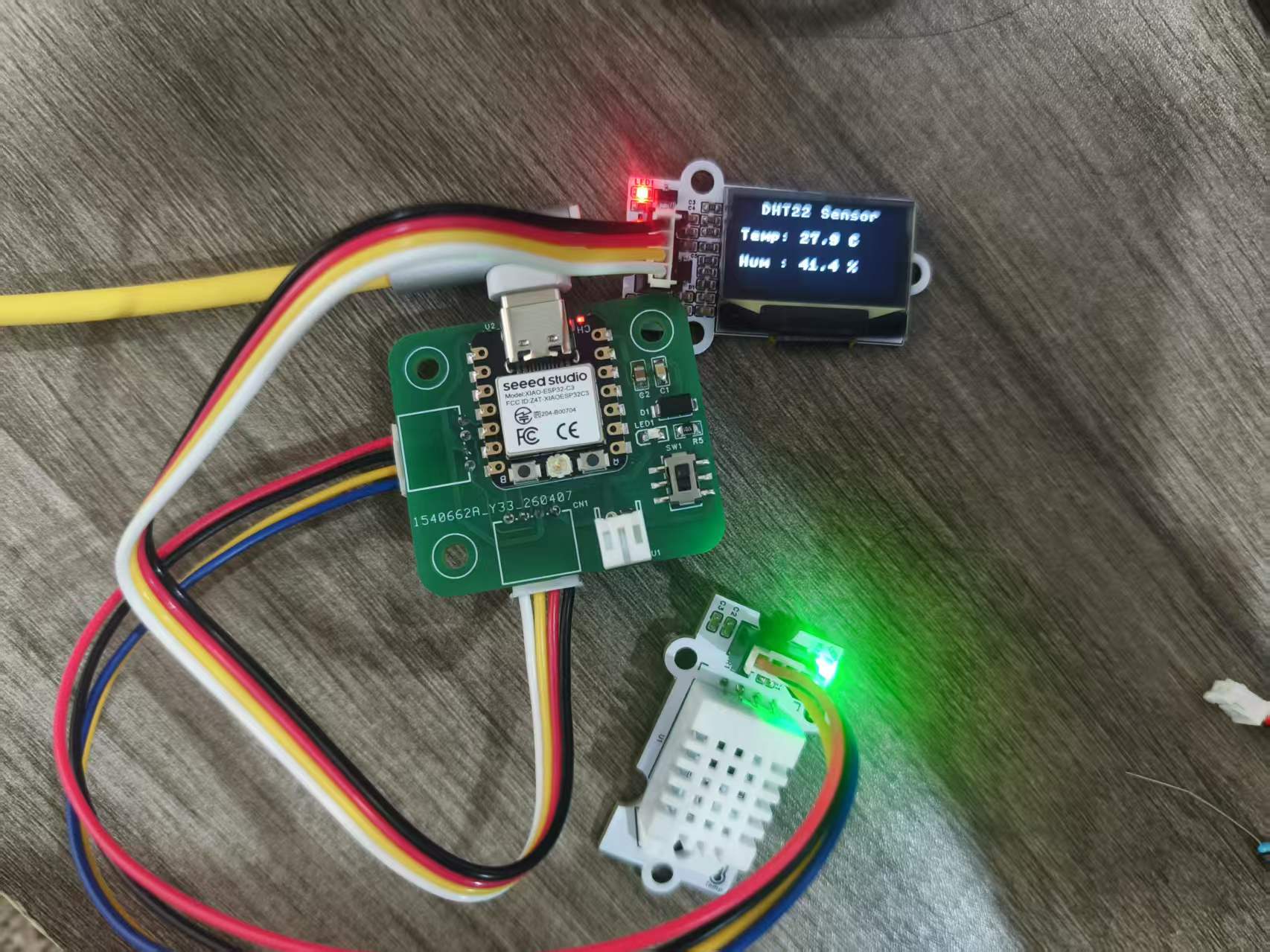
During the debugging process, I also checked the serial port output logs through the MicroPython Development Environment. The DHT22 temperature and humidity sensor can stably read and output data; when blowing air at the sensor, the serial port data shows that the temperature and humidity values increase with environmental changes, indicating that both the sensor data collection and OLED display logic are functioning properly.
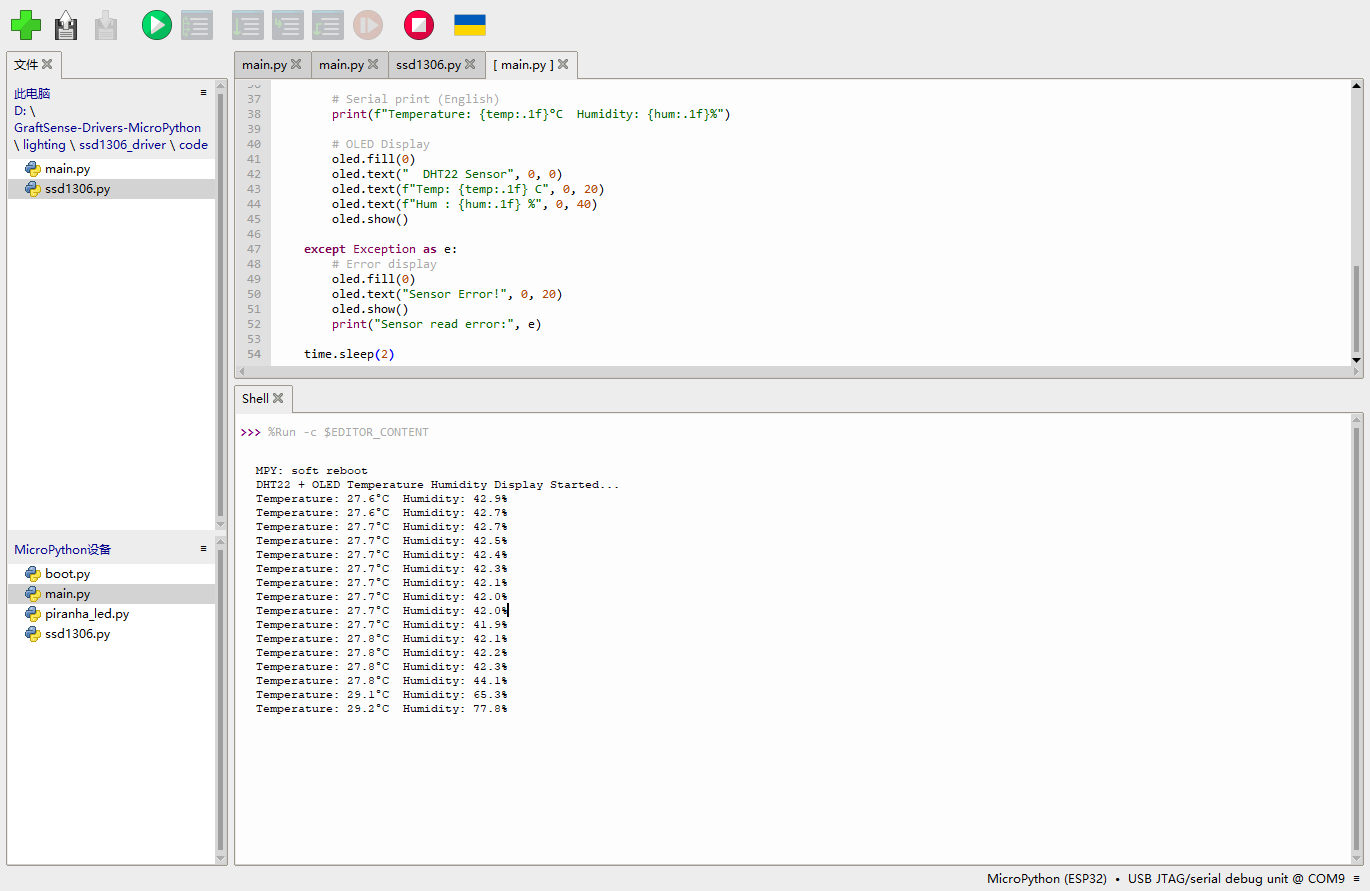
Finally completed the closed-loop verification from DHT22 input data to OLED output display.
5. Association with Power Consumption Testing
During the group assignment, the operating power consumption of the OLED module was measured, which is very helpful for the individual assignment. Since the OLED is the main output device in this individual project, it will continuously refresh and display temperature and humidity data. If we hope to power this device with a battery in the future, we need to pay attention to the current consumption of the OLED.
In the current program, the OLED refreshes every 2 seconds. Compared to high-frequency refreshing, this approach can reduce unnecessary screen updates and is also beneficial for reducing power consumption. If further optimization is needed in the future, the following can be considered:
- Reduce OLED brightness;
- Extend the refresh interval;
- When environmental data remains unchanged, the screen is not refreshed;
- Turn off the OLED display when there is no operation for a long time;
- Use the button to wake up the screen.
This allows the output device to be more suitable for low-power applications while maintaining readability.
6. Design Documents and Bill of Material
The source files of the development board used this week are from the self-designed development board files of the previous Electronics Design / Electronic Product Production Week.
The list of materials/files related to output devices is as follows:
| Name | Quantity | Description |
|---|---|---|
| Independently Produce ESP32-C3 / XIAO-C3 Development Board | 1 | Main Control and Interface Expansion |
| 0.96-inch SSD1306 OLED Module | 1 | Output device, used to display temperature and humidity |
| DHT22 Temperature and Humidity Sensor Module | 1 | Input device, used for collecting data |
| Connection Line | Several | 连接 VCC、GND、SDA、SCL、DATA |
| MicroPython Firmware | 1 | Run the control program |
| SSD1306 Driver Library | 1 | OLED Display Driver |
7. Summary
Through this week's assignment, I completed a simple temperature and humidity display device. The DHT22 is responsible for collecting temperature and humidity data, the ESP32-C3 is responsible for reading and processing the data, and the SSD1306 OLED is responsible for displaying the results. This process has allowed me to more clearly understand the role of output devices in embedded systems: they are not only for "displaying information", but also an important part of system status feedback.
Meanwhile, the power consumption test in the group project made me realize that the choice of output devices directly affects the power supply design of the project. For battery-powered devices, output devices such as displays, motors, and buzzers all need to undergo power consumption evaluation, and we cannot focus solely on whether the functions are implemented. In subsequent projects, I will consider the power consumption and refresh strategy of output devices during the design phase.
Attachment
ProPrj_GraftPort-XIAO扩展板_2026-03-14.epro2
BOM_Board1_PCB1_2026-06-09.xlsx
AI Assistance:
During the preparation of this documentation, ChatGPT (GPT-4) was used as a language assistance tool.
It helped with sentence polishing and translation from Chinese to English to improve readability and clarity.