Week 16 - System Integration
The theme of this week is System Integration . The task requirements given on the course page are:
Course Page: https://fabacademy.org/2026/classes/system_integration/index.html
This week, I will address a problem: how to integrate the various subsystems in the final project into a stable and functional whole .
Therefore, this week I will document the design, interfaces, assembly, testing, and risk handling of Maker Assistant during the system integration phase.
1. Understanding of This Week's Tasks
System integration is not about making a single component or debugging a single program in isolation, but rather about integrating mechanical structure, electronic circuits, embedded programs, computer software, communication protocols, power supplies, and user feedback methods together.
For my final project Maker Assistant , the core objective of system integration is to ensure that the following link truly functions smoothly:
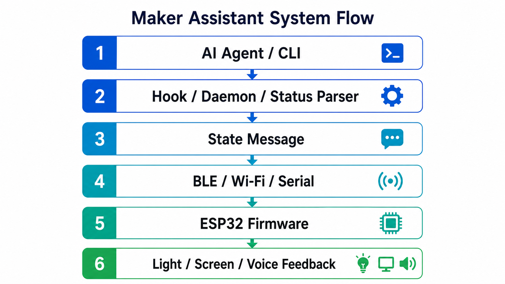
That is to say, the project cannot simply stay at individual functions such as "the light can turn on", "ESP32 can run", and "there are scripts on the computer", but rather needs to verify: when the state of the AI Agent changes, whether the desktop device can receive the state in a timely manner and provide feedback to the user through light, voice, or screen.
2. Project System Boundary
Maker Assistant is a desktop status feedback device designed for AI programming workflows. It can convert the execution status of Claude Code, Codex CLI, or similar AI Agent tools in the terminal into feedback on a physical device.
This week, system integration focuses on the following parts:
- How to capture Agent status on the computer?
- How is the state organized into a unified message;
- How to send messages to ESP32 via BLE;
- How does ESP32 parse the status;
- How does the device control lights, voice, and screen;
- How to insert the electronic module into the housing;
- How to assemble the housing, PCB, speaker, lighting, and wires;
- How to test and troubleshoot the entire system.
This week, we will not focus on elaborating on the complete project background, cost estimates, licenses, future development, etc., as these are part of the final project master document. Here, we will focus on documenting how the systems are connected and coordinated.
3. Overall System Architecture
The complete system of Maker Assistant can be divided into four layers.
3.1 Agent Status Source
The state sources are Claude Code, Codex CLI, or similar AI Agent tools. They may exhibit different states during operation, for example:
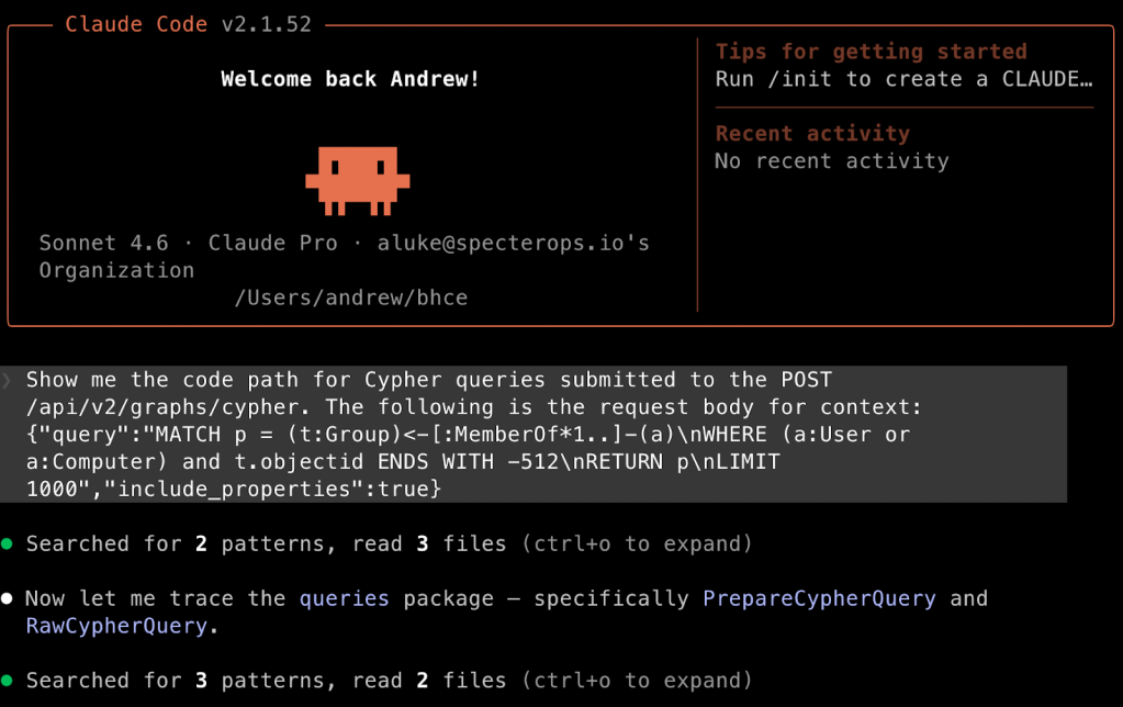
- Command is being executed;
- Waiting for user approval;
- Command execution failed;
- The test did not pass;
- The task has been completed;
- Connection is disconnected or device is unavailable.
These states were originally hidden in the terminal text, and users had to keep staring at the screen to discover them. What this project aims to do is to transfer these states to a physical desktop device.
3.2 Computer Terminal Status Capture and Forwarding
The computer client captures Agent events through Hook, daemon process, and state parser, and then organizes events from different sources into unified status messages.
The computer mainly accomplishes three tasks:
- Receive Claude Code Hook or other Agent events;
- Determine the current system status, such as working, pending, completed, error;
- Continuously send status to ESP32 device via BLE.
3.3 Communication Layer
This project mainly uses BLE as the communication method between the computer and the device. The reason for choosing BLE is that Maker Assistant is a desktop device, and cables should be minimized. The device can be powered via USB, while status data is transmitted via Bluetooth.
Subsequent systems can also be extended to Wi-Fi, WebSocket, or serial communication, but in the current Clock version, the data volume of BLE is already sufficient.
3.4 Hardware Feedback Layer
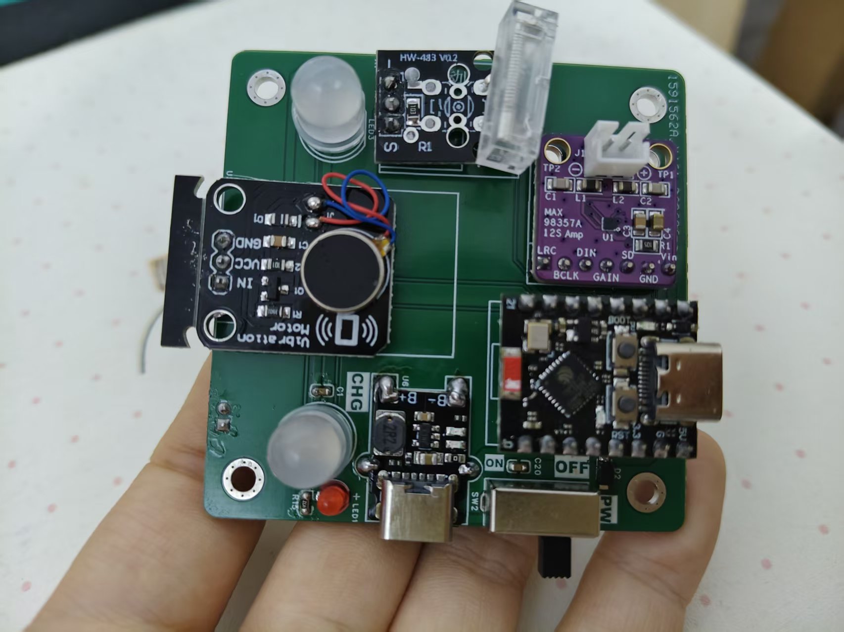
After receiving the status, the ESP32 will control the hardware output:
- WS2812B RGB LED is used for status color and blinking rhythm;
- MAX98357A I2S power amplifier and speaker are used for voice alerts;
- The Panel / D-Shell version can also use a TFT screen to display animations and text;
- A vibration motor or vibration sensor can serve as auxiliary feedback.
4. System Integration - Electronic Part
This project finally uses Clock Alarm Edition as the main manufacturable version. The Clock version has a simpler structure and is suitable for completing the full closed loop from electronic connections, firmware, enclosure to assembly testing in the Fab Lab.
The electronic system is centered around the ESP32-C3, which is responsible for BLE communication, status parsing, lighting control, and I2S audio output.
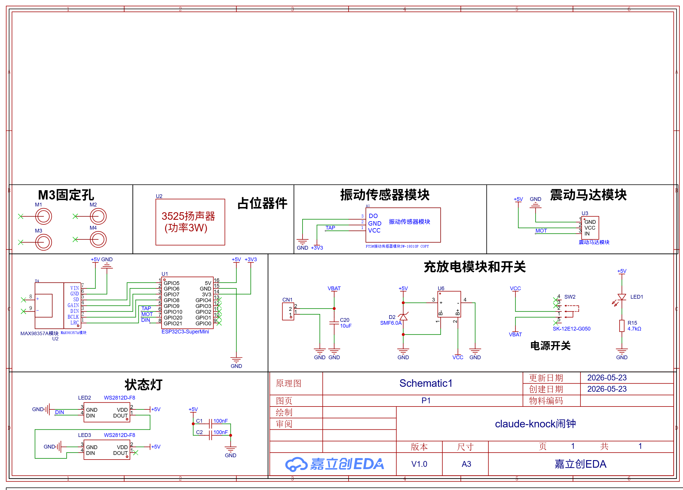
The main hardware components are as follows:
| Category | Component or Material | Function |
|---|---|---|
| Master Control | ESP32-C3 Development Board | BLE communication, status parsing, lighting control, and audio output |
| Lighting | WS2812B RGB LED | Displays states such as idle, working, pending, completed, and error |
| Audio | MAX98357A I2S Digital Power Amplifier Module | Drive the speaker to play voice prompts |
| Sound Output | 4Ω / 3W Small Speaker | Play startup, connection, waiting for approval, completion, and error prompts |
| Circuit connection | Self-made PCB / Pin Header / Dupont Wire | Connect ESP32, LED, amplifier, speaker, and interface |
| Structural fixation | M2 / M3 screws, nuts, heat-set brass inserts | Fix the housing, PCB, and speaker |
4.1 Circuit Connection
In the early prototype, I could use DuPont wires to verify whether the ESP32, LED, and power amplifier could work independently. However, the system integration phase requires a more stable connection method, so I used PCBs or pin headers to organize the connection relationships.
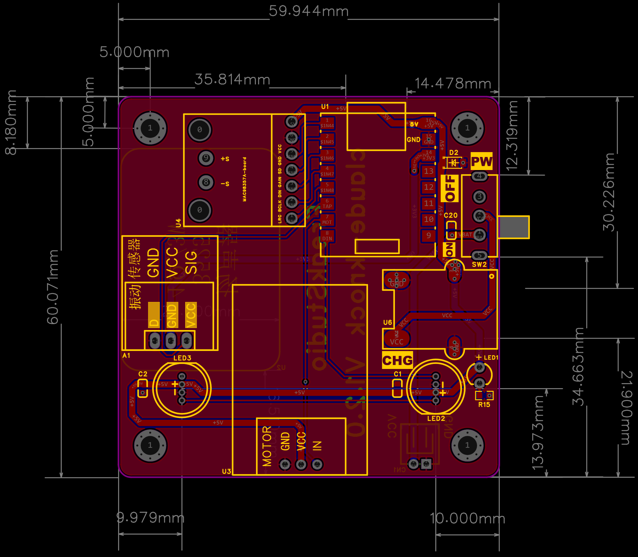
The main connections are as follows:
| Module | Connection Method | Description |
|---|---|---|
| WS2812B VCC | 5V | Power the RGB LED |
| WS2812B GND | GND | Shares ground with ESP32 |
| WS2812B DATA | ESP32 GPIO | Receive lighting control data |
| MAX98357A VIN | 5V / 3.3V | Power the digital power amplifier |
| MAX98357A GND | GND | Shares ground with ESP32 |
| MAX98357A BCLK | ESP32 I2S BCLK | I2S Bit Clock |
| MAX98357A LRC | ESP32 I2S LRC | I2S Left and Right Channel Clock |
| MAX98357A DIN | ESP32 I2S DATA | Audio data input |
| Speaker | MAX98357A Output | Play voice prompt |
4.2 Electrical Integration Precautions
In electronic integration, I focus on the following issues:
- All modules must be grounded together; otherwise, LED data and I2S audio may be unstable;
- WS2812B is relatively sensitive to power supply, and unstable power supply may lead to abnormal colors or flickering;
- Speakers and power amplifiers need to have sufficient space to avoid sound being blocked after being installed in the enclosure;
- The wire should not be squeezed by the housing, otherwise it is prone to breakage when moving the device later;
- The PCB size needs to fit the internal space of the enclosure.
5. State Protocol Integration
The core of system integration is not to make devices play fixed animations, but to enable the computer and ESP32 to understand the same set of state protocols.
Status messages sent from the computer should be kept as brief as possible, for example:
s=W;p=project-name;m=running
s=P;p=project-name;m=waiting approval
s=C;p=project-name;m=completed
s=E;p=project-name;m=error
where s represents the device state:
| state | Meaning | Device Feedback |
|---|---|---|
| I | Idle | Soft lighting or standby animation |
| W | Working is in progress | Breathing light or running animation |
| P | Pending Approval | Yellow flashing and voice reminder |
| C | Completed Task | Green light and completion beep |
| E | Error occurred | Red light and error beep |
| D | Disconnected | Gray state or disconnection prompt |
This protocol is more suitable for BLE transmission than full natural language, and also facilitates parsing on the ESP32 side. Shorter status messages lead to more stable device-side logic and easier debugging.
6. System Integration - Software Component
The software system is divided into the computer side and the device side.
6.1 Desktop
The computer client mainly consists of a Python daemon process and Hook Bridge. They are responsible for receiving events generated by Claude Code or similar tools and converting them into a unified state.
The computer side needs to complete the following tasks:
- Receive Claude Code Hook payload;
- Standardize different events;
- Maintain the current finite-state machine;
- Scan and connect to BLE devices;
- Push status messages to the device;
- Handle disconnection and automatic reconnection;
- Provides tools for programming, pairing, and configuration.
Key modules include:
| File / Module | Function |
|---|---|
| daemon/hook_bridge.py | Receive Hook payload and convert it into an internal event |
| daemon/ble_daemon.py | Maintain the finite-state machine and periodically push the state |
| daemon/transport.py | is responsible for BLE connection, sending, and automatic reconnection |
| daemon/pair_device.py | Scan and pair devices |
| hooks/hooks.json | Claude Code Hook Registration Configuration |
| setup_tool/ | Graphical programming, configuration, and pairing tool |
6.2 ESP32 Device Side
The ESP32 firmware is written in MicroPython. The firmware differentiates based on hardware form factors clock, panel and dshell, so that the same set of code can support different device versions.
The device side needs to complete the following tasks:
- Initialize lights, audio, and screen;
- Receive BLE status messages;
- Parse the state protocol;
- Update the internal finite-state machine of the device;
- Refresh lights, voice, and animations based on the state;
- Handle disconnection and reconnection;
- Keep the main loop running stably.
The device-side logic is as follows:
7. System Integration - Structural Part
The structure of Maker Assistant is not a simple electronic box, but a desktop character device. Therefore, structural integration needs to consider both internal space and external styling simultaneously.
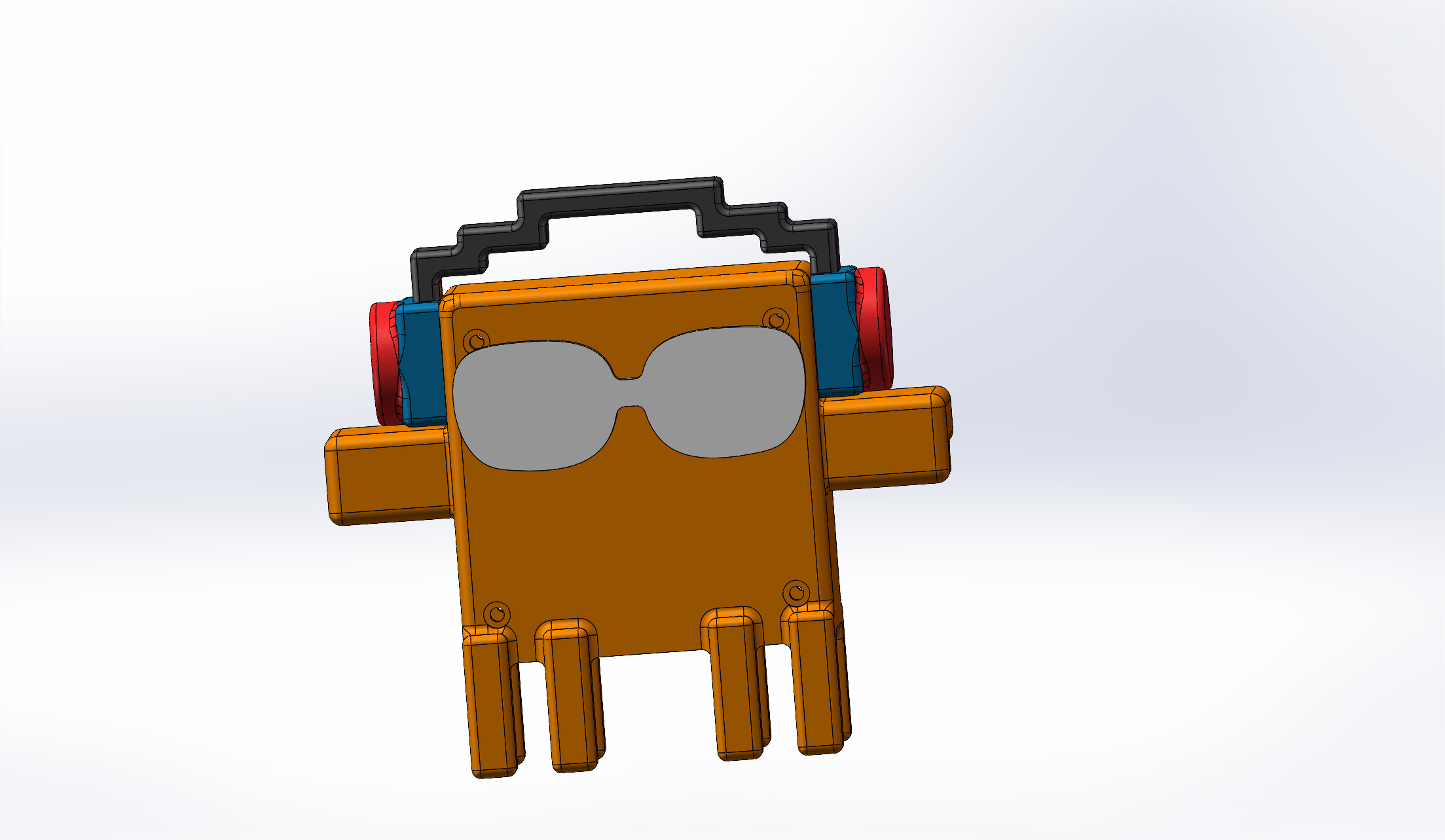
The shell and character accessories were modeled using SolidWorks and fabricated through FDM 3D printing. The key points of the structural design are as follows:
- The interior of the main body needs to accommodate PCB, ESP32, speakers, and wires;
- The exterior needs to carry role accessories such as glasses and hats;
- The bottom should be stable enough to prevent tipping over when used on a desktop;
- The speaker location must have an opening or a sound channel;
- The housing needs to be detachable for easy inspection and maintenance;
- Accessories are best printed separately to reduce the cost of printing failure.
8. Assembly Process
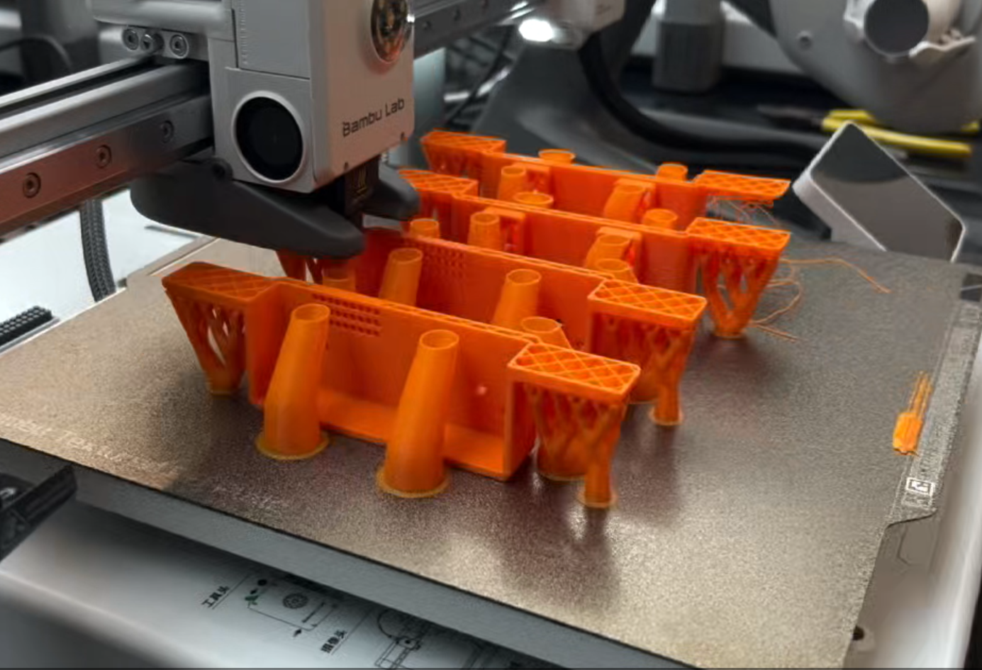
8.1 Printed Enclosures and Structural Components
First, print the main body, glasses, ears, feet, and other accessories. After printing, check the dimensions, tolerances, screw hole positions, and appearance proportions.
8.2 Prepare PCB and Electronic Modules
Before installing into the housing, first check whether the PCB, ESP32, power amplifier, speaker, and LED can operate independently. This stage mainly checks for short circuits, power supply, LED output, and audio playback.
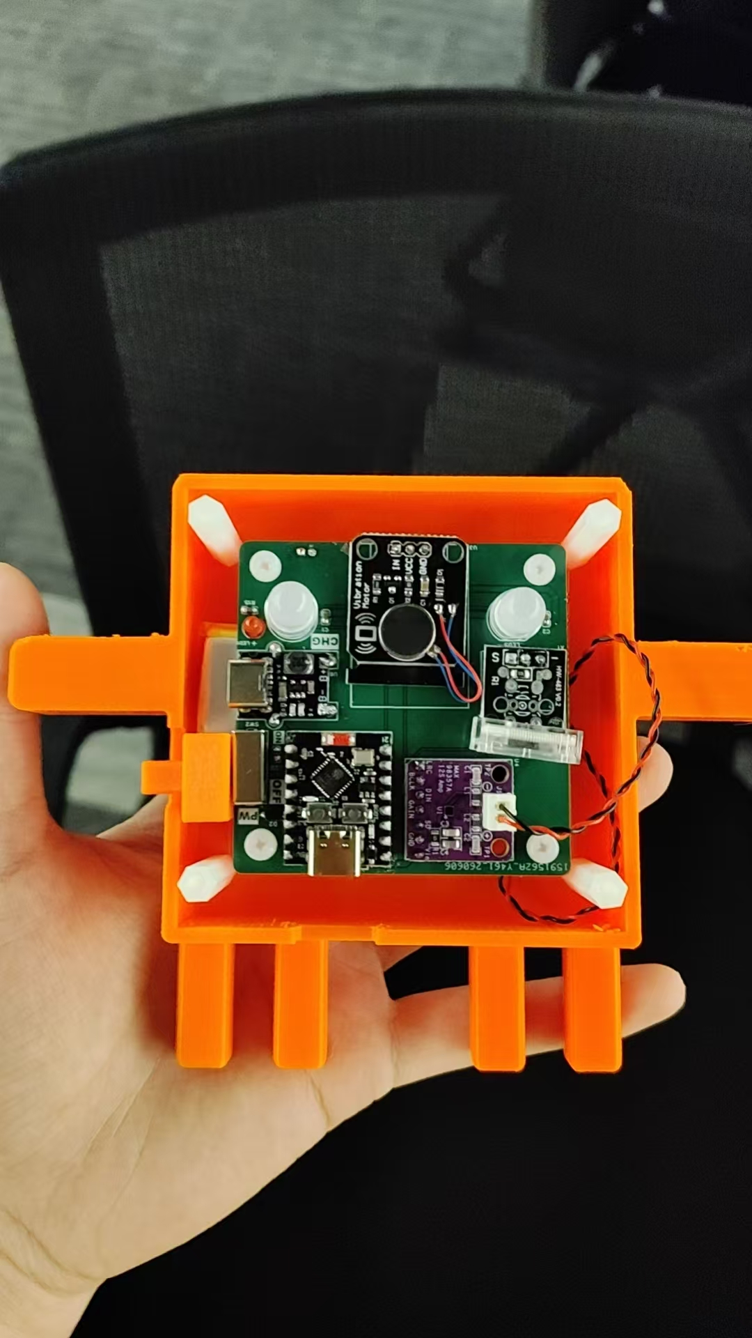
8.3 Install Speakers and Internal Components
The speaker needs to be fixed inside the housing and as close as possible to the opening position. During installation, avoid having the speaker pressed by wires, and also avoid wires affecting the enclosure assembly.
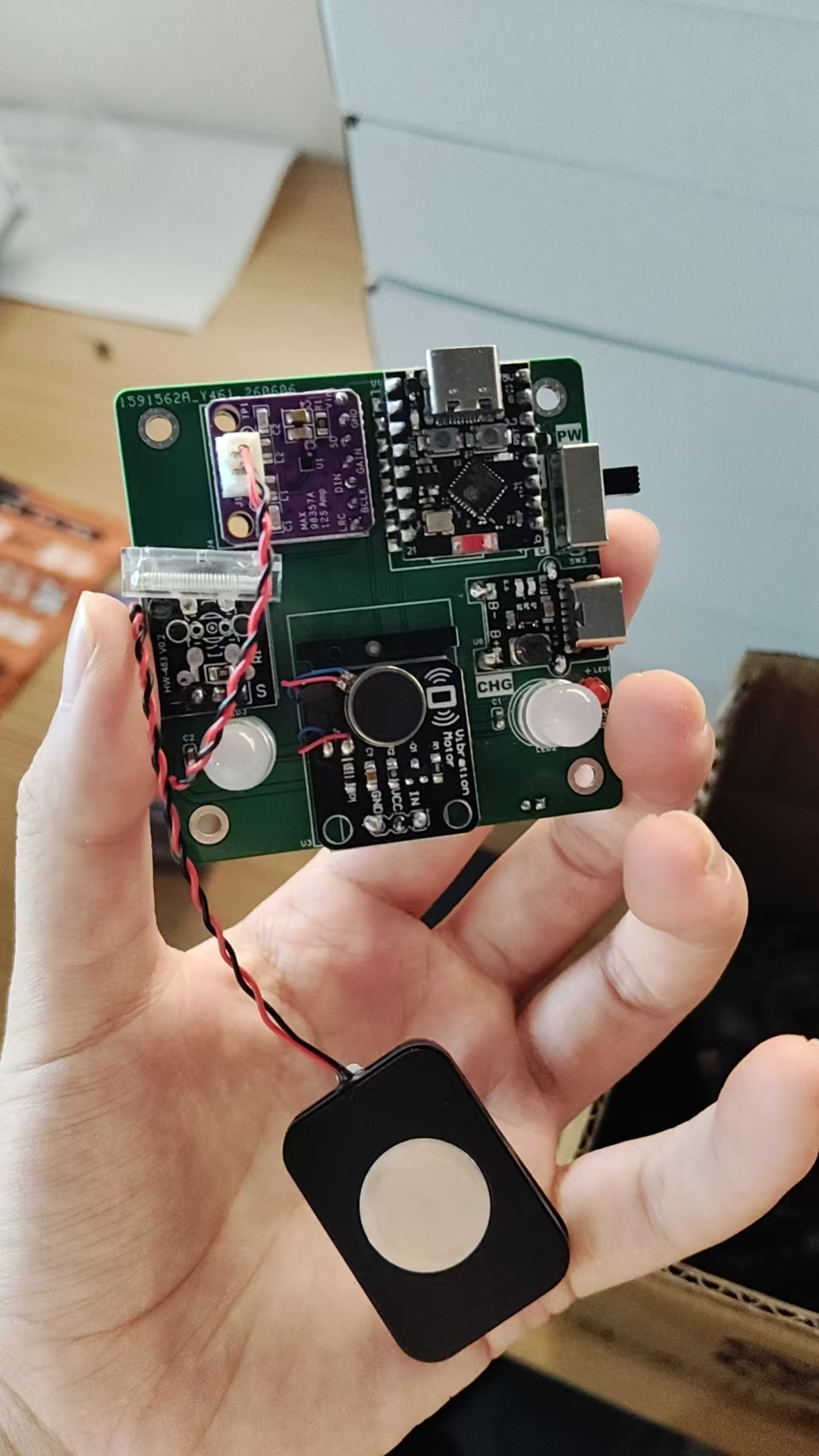
8.4 Secure the main control board and organize the wires
The organization of the main control board and wires is a very important step in system integration. If the wires are too messy, the enclosure may not close properly, and it will also increase the risk of later wire breakage and poor contact.
8.5 Enclosure Assembly and Power-on Test
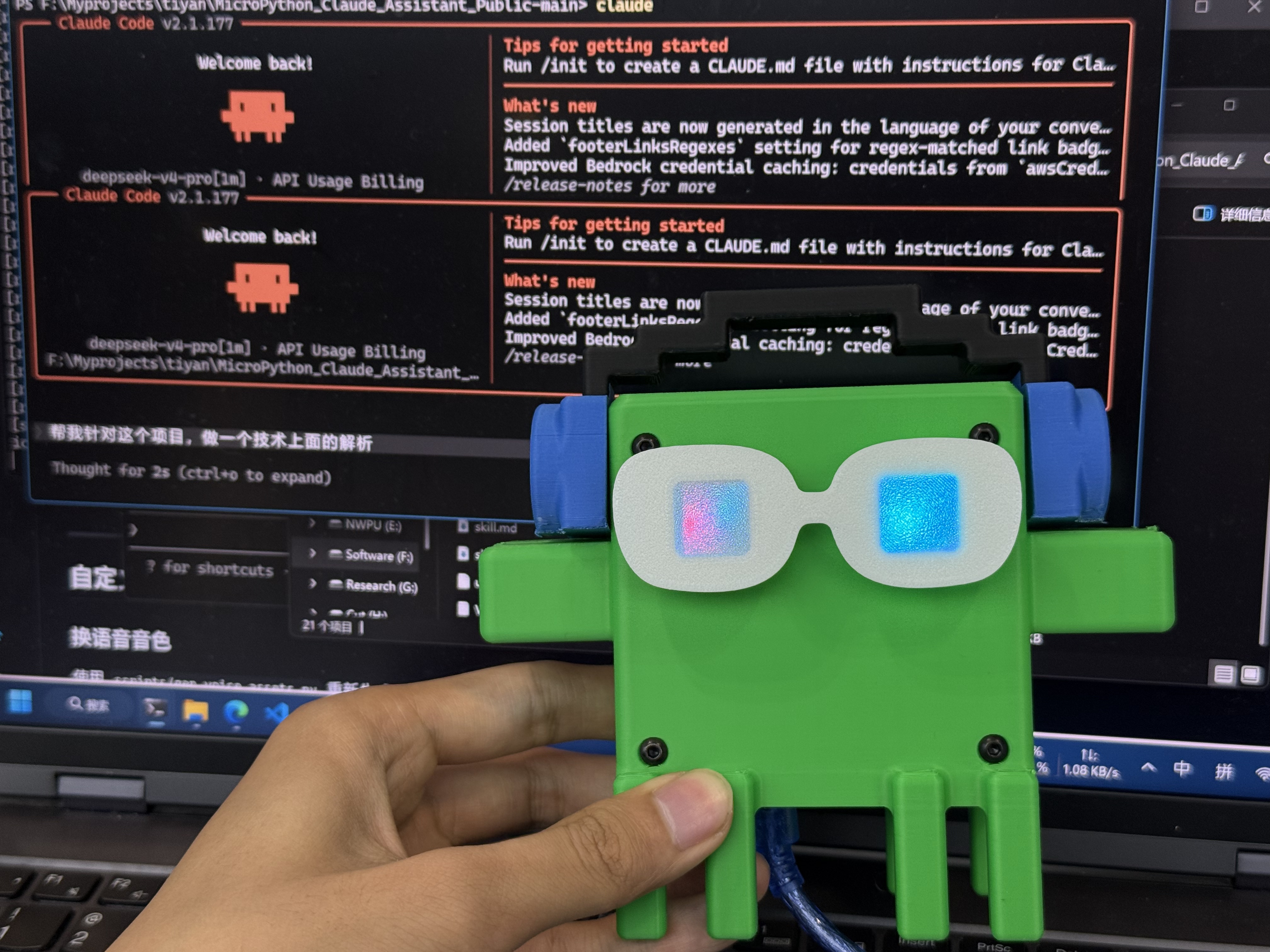
After confirming that all modules are operational, close the enclosure and conduct a power-on test. The test items include BLE connection, light change, voice playback, and status switching.
9. Issues Encountered During Integration
9.1 The internal space is more cramped than in CAD
The space that seems sufficient in CAD will be occupied by wires, pin headers, and bend radii during actual assembly. Especially DuPont wires and connectors will take up more space than the components themselves. Subsequent versions should minimize flying wires and use more compact PCBs and connectors.
9.2 BLE stability requires continuous optimization
BLE is suitable for desktop devices, but in a Windows environment, it may encounter issues such as pairing failures, disconnections, or device being occupied. Therefore, the computer side must have reconnection logic, and the device side should also be able to display the disconnected status.
9.3 Voice reminders need to be moderate
If each event plays a voice, the device will become very noisy. After system integration, I found that voice is most suitable for waiting for approval, error, and completion statuses, while the in-work status is more suitable to be expressed by lights.
9.4 The enclosure cannot be completely sealed
If glue is used to secure all structures, the appearance may be cleaner, but it cannot be repaired later. Ultimately, I prefer to use screws and detachable structures to facilitate reprogramming, circuit inspection, and component replacement.
10. This Week's Summary
Through this week's system integration, I have connected multiple subsystems of Maker Assistant into a complete working link:
This process demonstrates that the Maker Assistant is not a standalone lighting experiment, nor a standalone desktop enclosure, but a system composed of software, communication, embedded hardware, and structural assembly.
The difference between this week's document and the final project document lies in that the final project document describes the background, objectives, production process, and evaluation of the entire project; while this week's document focuses on recording system integration, including how modules are connected, how states flow, how the structure accommodates the electronic system, and how the entire link is ultimately verified.
Currently, the most mature version is the Clock Alarm version, which has achieved BLE communication, status lights, voice reminders, and desktop assembly with relatively low hardware complexity. The Panel / D-Shell version, on the other hand, demonstrates the direction of future expansion towards screen animations and multi-session status display.
Further optimization is still needed:
- Improve BLE connection stability;
- Optimize PCB and wire layout;
- Improve the internal space of the enclosure;
- Reduce voice disturbances;
- Support more AI Agent tools;
- Add a more complete state history display for the screen version.
AI Assistance:
During the preparation of this documentation, ChatGPT (GPT-4) was used as a language assistance tool.
It helped with sentence polishing and translation from Chinese to English to improve readability and clarity.